
Related Manuals for TSI Instruments PRESSURA 8630-SM


Summary of Contents for TSI Instruments PRESSURA 8630-SM
- Page 1 PRESSURA™ ROOM PRESSURE MONITOR MODELS 8630-SM 8630-PM OPERATION AND SERVICE MANUAL P/N 1980242, REVISION G JUNE 2013...
- Page 3 PRESSURA™ ROOM PRESSURE MONITOR MODELS 8630-SM 8630-PM OPERATION AND SERVICE MANUAL P/N 1980242, REVISION G JUNE 2013 U.S. AND CANADA OTHER COUNTRIES Sales & Customer Service: Sales & Customer Service: (800) 874-2811/(651) 490-2811 (001 651) 490-2811 Fax: Fax: (651) 490-3824 (001 651) 490-3824 SHIP/MAIL TO: E-MAIL...
- Page 4 COPYRIGHT - TSI Incorporated / 2000–2013 / All rights reserved. PART NUMBER 1980242 / Rev. G LIMITATION OF WARRANTY AND LIABILITY (effective June 2011) (For country-specific terms and conditions outside of the USA, please visit www.tsi.com.) Seller warrants the goods sold hereunder, under normal use and service as described in the operator's manual, shall be free from defects in workmanship and material for twenty-four (24) months, or if less, the length of time specified in the operator's manual, from the date of shipment to the customer.
-
Page 5: Table Of Contents
CONTENTS HOW TO USE THIS MANUAL ....................... iii PART ONE USER BASICS ..................1 The Instrument ..................1 Operator Panel ..................3 Alarms ....................... 5 Before Calling TSI ..................6 PART TWO TECHNICAL SECTION ................7 Software Programming ................8 Menu and Menu Items ................ - Page 6 (This page intentionally left blank)
-
Page 7: Part One User Basics
Part One User Basics Reading product manuals should not be a difficult and time-consuming process. This section provides a brief but thorough overview of the PresSura product by maximizing information with minimal reading. These few pages explain the purpose (The Instrument), and the operation (Useful User Information, Digital Interface Module, Alarms) of the unit. - Page 8 An example of negative pressure is a bathroom with an exhaust fan. When the fan is turned on, air is exhausted out of the room creating a slight negative pressure in the bathroom compared to the hallway. This pressure differential forces air to flow from the hallway into the bathroom.
-
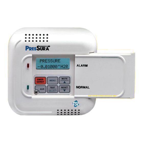
Page 9: Operator Panel
Operator Panel The DIM in Figure 3 shows the location of the digital display, keypad and lights. An explanation of the operator panel follows the figure. Figure 3: PresSura Operator Panel - Open Green / Red light The green light is on when all the conditions for proper room pressure are adequate. This light indicates the isolation room is operating safely. - Page 10 User Keys - Gray with Black Letters The four keys with black letters provide information without changing the operation or the function of the unit. TEST Key The TEST key initiates an instrument self-test. Pressing the TEST key activates a scrolling sequence on the display that shows the product model number, software version, and alarm values.
-
Page 11: Alarms
Alarms PresSura controller has visual (red light) and audible alarms to inform you of changing conditions. The alarm levels (set points) are determined by hospital personnel, which could be the infection control group, charge nurse, or a facilities group depending on the hospital organization. -
Page 12: Before Calling Tsi
Before Calling TSI The manual should answer most questions and resolve most problems you may encounter. If you need assistance or further explanation, contact your local TSI representative or TSI. TSI is committed to providing high quality products backed by outstanding service. -
Page 13: Part Two Technical Section
Part Two Technical Section The PresSura controller is ready to use after being properly installed. The pressure sensor is factory calibrated prior to shipping, and should not need adjustment. The Digital Interface Module (DIM) is programmed with a default configuration that can be easily modified to fit your application. -
Page 14: Software Programming
Software Programming Programming the PresSura Room Pressure Controller is quick and easy if the programming keys are understood, and the proper key stroke procedure is followed. The programming keys are defined first, followed by the required keystroke procedure. At the end of this section is a programming example. - Page 15 SELECT Key The SELECT key has three functions. The SELECT key is used to gain access to specific menus. To access a menu, scroll through the menus (using arrow keys) and place the flashing cursor on the desired menu. Press the SELECT key to select the menu.
- Page 16 If more than one item is to be changed, skip steps 8 and 9 until all changes are complete. If more items in the same menu are to be changed, scroll to them after saving the data (step 7). If other menus need to be accessed, press the MENU key once to access list of menus.
- Page 17 Press the SELECT key to save the new SELECT positive low alarm set point. Three short beeps will sound POS LOW ALM indicating that the data is being Saving Data saved. Immediately after the data is saved, ALARM the PresSura controller will return to POS LOW ALM the menu level displaying the menu title on the top line of the display and...
-
Page 18: Menu And Menu Items
Menu and Menu Items The PresSura controller is a very versatile device which can be configured to meet your specific application. This section lists all of the menu items available to program and change (except diagnostics menu). Changing any item is accomplished by using the keypad, or if communications are installed through the RS-485 Communications port. - Page 19 ALARM CONFIGURE CALIBRATION INTERFACE DIAGNOSTICS NEG LOW ALM ROOM MODE SENSOR ZERO NET PROTOCOL SENSOR INPUT NEG HIGH ALM DISPLAY AVG SENSOR SPAN NET ADDRESS SENSOR STAT POS LOW ALM UNITS FLOW ZERO OUTPUT RANGE ANALOG OUT POS HIGH ALM DUCT AREA 2SENSOR ZERO OUTPUT SIG...
- Page 20 ALARM MENU SOFTWARE DEFAULT MENU ITEM NAME ITEM DESCRIPTION ITEM RANGE VALUE NEGATIVE NEG LOW The NEG LOW ALM item sets the negative low pressure alarm OFF, 0 to -0.19500 set point. A low alarm condition is defined as when the "H PRESSURE magnitude of the room pressure falls below or goes in the...
- Page 21 ALARM MENU (continued) SOFTWARE DEFAULT MENU ITEM NAME ITEM DESCRIPTION ITEM RANGE VALUE The MIN CFM ALM item sets the duct’s flow alarm set point. A MINIMUM MIN CFM OFF, 0 to 2832 ft/MIN DUCT FLOW minimum flow alarm is defined as when the duct flow is less times the duct area in ALARM than the MIN CFM ALM set point.
- Page 22 ALARM MENU (continued) SOFTWARE DEFAULT MENU ITEM NAME ITEM DESCRIPTION ITEM RANGE VALUE The 2 HIGH ALM item sets the second sensor’s high alarm set SECOND 2 HIGH ALM OFF, 0 to +0.19500 SENSOR HIGH point. A high alarm condition is defined as when the magnitude "H of the second sensor’s room pressure rises above the 2 HIGH ALARM...
- Page 23 ALARM MENU (continued) SOFTWARE DEFAULT MENU ITEM NAME ITEM DESCRIPTION ITEM RANGE VALUE ALARM DELAY ALARM The ALARM DELAY determines the length of time the alarm is 20 to 600 SECONDS DELAY delayed after an alarm condition has been detected. This delay SECONDS affects the visual alarm, audible alarm, and relay outputs.
- Page 24 Example: The LOW ALARM set point is -0.00072 “H O. The HIGH ALARM set point cannot be set lower than -0.00128 “H Second sensor alarms can be programmed for positive or negative pressure. Both the second sensor low and high alarms must be programmed either positive or negative.
- Page 25 CONFIGURE MENU SOFTWARE DEFAULT MENU ITEM NAME ITEM DESCRIPTION ITEM RANGE VALUE ROOM MODE ROOM The ROOM MODE item selects the room pressure direction. KEY SWITCH, NEGATIVE MODE This item enables all related alarms for pressure direction NEGATIVE, selected. Selecting key switch enables a remote TSI key POSITIVE, NO switch, which determines pressure direction.
- Page 26 CONFIGURE MENU (continued) SOFTWARE DEFAULT MENU ITEM NAME ITEM DESCRIPTION ITEM RANGE VALUE SECOND 2 SENSOR The 2 SENSOR item turns the second sensor on or off. This ON or OFF SENSOR item requires a second TSI pressure sensor to be installed in ENABLE order to function.
- Page 27 CONFIGURE MENU (continued) SOFTWARE DEFAULT MENU ITEM NAME ITEM DESCRIPTION ITEM RANGE VALUE SENSOR SENSOR The SENSOR SPAN item is used to match or calibrate the NONE Unit is factory SPAN SPAN PresSura velocity sensors to the average room pressure calibrated.
- Page 28 CONFIGURE MENU (continued) SOFTWARE DEFAULT MENU ITEM NAME ITEM DESCRIPTION ITEM RANGE VALUE SECOND 2SENSOR The 2SENSOR SPAN item is used to match or calibrate the NONE Unit is factory SENSOR SPAN second PresSura velocity sensors to the average room calibrated.
- Page 29 INTERFACE MENU SOFTWARE DEFAULT MENU ITEM NAME ITEM DESCRIPTION ITEM RANGE VALUE NETWORK The NET PROTOCOL item selects the communications MODBUS MODBUS PROTOCOL PROTOCOL protocol used to interface with the building management system. CIMETRICS Premium models only NETWORK The NET ADDRESS item is used to select the main network 1 to 247 ADDRESS ADDRESS...
- Page 30 INTERFACE MENU (continued) SOFTWARE DEFAULT MENU ITEM NAME ITEM DESCRIPTION ITEM RANGE VALUE OUTPUT The PresSura controller updates the analog output every 0.1 LOW or HIGH HIGH OUTPUT RANGE second. This signal outputs a linear 0 to 10 volt direct current RANGE (continued) (VDC) or 4 to 20 mA DC analog output which corresponds to...
-
Page 31: Calibration
Calibration The calibration section explains how to calibrate the PresSura pressure sensor, including setting the proper elevation, and how to zero a TSI flow station pressure transducer. NOTE: The PresSura pressure sensor is factory calibrated and normally does not need to be adjusted. - Page 32 Figure 7: Pressure sensor door slid open. Sensor span NOTE: Always take a sensor zero prior to adjusting the sensor span. A smoke test and a comparison measurement by an air velocity meter are required to calibrate the pressure sensor. The air velocity meter only gives a velocity reading, so a smoke test must be performed to determine pressure direction.
-
Page 33: Maintenance And Repair Parts
Maintenance and Repair Parts The Model 8630 PresSura Room Pressure Monitor requires minimal maintenance. Periodic inspection of the system components, as well as an occasional pressure sensor cleaning, are all that are needed to ensure that the Model 8630 is operating properly. System Component Inspection It is recommended that the pressure sensor be periodically inspected for accumulation of contaminants. - Page 34 Replacement Parts All components of the room pressure monitor are field replaceable. Contact TSI HVAC Control Products at (800) 874-2811 (U.S. and Canada) or (001 651) 490-2811 (other countries) or your nearest TSI Manufacturer's Representative for replacement part pricing and delivery. Part Number Description 800244...
-
Page 35: Troubleshooting Section
Troubleshooting Section The PresSura Room Pressure Monitor is designed to be trouble free. However, installation problems or interaction with other HVAC components may cause system problems. The PresSura system is easy to troubleshoot if an organized approach to evaluate the system is taken. Troubleshooting is broken down into hardware and software problems. - Page 36 TEST - DIM Press TEST key to verify Digital Interface Module (DIM) electronics are functioning correctly. At the end of the self test, the display will show SELF TEST - PASSED if all DIM electronics are good. If unit displays DATA ERROR at the end of the test, the electronics may be corrupted.
- Page 37 Diagnostics menu The items in the diagnostic menu (listed below) aid in identifying problems the staff may encounter. The items in this menu temporarily change the function by pressing the / keys. No permanent change occurs with these menu items. Items are exited by pressing the MENU key.
- Page 38 Key Switch Input Menu Item - KEY INPUT The KEY INPUT item reads the position of the TSI key switch. When this item is entered, the display will indicate either POSITIVE, NEGATIVE, or NO ISOLATION. If the display indicates POSITIVE, the TSI key switch has the PresSura controller in positive pressure mode.
- Page 39 Troubleshooting Chart Symptom Possible Cause Corrective Action Display is blank. Fuse is blown. Measure voltage at pins 1 and 2 on DIM. The voltage should nominally be 24 - 30 VAC. If correct voltage is measured, internal DIM fuse is probably blown.
- Page 40 Symptom Possible Cause Corrective Action DIM displays Sensor direction is Pressure sensor must have DIP switch correctly set for opposite incorrect. proper sign display. Verify DIP switch 4 is ON when pressure signal. sensor is mounted in isolation room (controlled space), and OFF when mounted in reference space (see Figure Sensor does not Incorrect pressure...
- Page 41 Symptom Possible Cause Corrective Action Key switch in Key switch is not Change ROOM MODE to key switch. neutral but selected in ROOM alarms still MODE menu item. function. Key switch is Replace key switch (unlikely cause of problem). defective. DIM does not Network protocol Go into INTERFACE menu, NET PROTOCOL item.
- Page 42 Symptom Possible Cause Corrective Action Alarm relays Alarms are turned Press TEST key. The individual alarm set points will don't work. off. display. If all alarm set points are zero, alarm relay is not active, so relay will not be required to change state. Incorrect wiring.
-
Page 43: Appendix A Specifications
Appendix A Specifications Room Pressure Module Display Range ..............-0.20000 to +0.20000 inches H Resolution ............5% of reading Display Update ............ 0.5 sec Inputs Switch in .............. SPST (N.O.) Switch. Closing switch initiates condition. Flow in ..............SPST (N.O.) Switch. Closing switch initiates condition. - Page 44 (This page intentionally left blank) Specifications...
-
Page 45: Wiring Diagram
Appendix B Wiring Diagram Figure 10: Wiring Diagram Appendix B... - Page 46 (This page intentionally left blank) Wiring Diagram...
-
Page 47: Appendix C Access Codes
Appendix C Access Codes These are the access codes to the different menus of the PresSura Room Pressure Monitor. When an access code is required, pressing the following key sequence will provide access to the required menu. Key # Setpoints Alarm Configure Calibration... - Page 48 (This page intentionally left blank) Access Codes...
- Page 49 TSI Incorporated – Visit our website www.tsi.com for more information. Tel: +1 800 874 2811 India Tel: +91 80 67877200 Tel: +86 10 8219 7688 Tel: +44 149 4 459200 China France Tel: +33 4 91 11 87 64 Singapore Tel: +65 6595 6388 Germany Tel: +49 241 523030...
Need help?
Do you have a question about the PRESSURA 8630-SM and is the answer not in the manual?
Questions and answers