
Related Manuals for TSI Instruments EVERWATCH 8610


Summary of Contents for TSI Instruments EVERWATCH 8610
- Page 1 ® EVERWATCH FACE VELOCITY MONITOR MODEL 8610 OPERATION AND SERVICE MANUAL P/N 1980154, REVISION H FEBRUARY 2013...
- Page 3 ® EVERWATCH FACE VELOCITY MONITOR MODEL 8610 OPERATION AND SERVICE MANUAL P/N 1980154, REVISION H FEBRUARY 2013 U.S. AND CANADA OTHER COUNTRIES Sales & Customer Service: Sales & Customer Service: (800) 874-2811/(651) 490-2811 (001 651) 490-2811 Fax: Fax: (651) 490-3824 (001 651) 490-3824 SHIP/MAIL TO: E-MAIL...
- Page 4 Copyright TSI Incorporated / 1995–2013 / All rights reserved. Part number 1980154 / Revision H / February 2013 LIMITATION OF WARRANTY AND LIABILITY (effective June 2011) (For country-specific terms and conditions outside of the USA, please visit www.tsi.com.) Seller warrants the goods sold hereunder, under normal use and service as described in the operator's manual, shall be free from defects in workmanship and material for twenty-four (24) months, or if less, the length of time specified in the operator's manual, from the date of shipment to the customer.
-
Page 5: Table Of Contents
CONTENTS HOW TO USE THIS MANUAL ..................III PART ONE .......................... 1 User Basics .................. 1 The Instrument ................1 Operator Panel ................2 Alarms ..................3 Before Calling TSI ................ 4 PART TWO ......................... 5 Technical Section ................. 5 Software Programming .............. -
Page 7: Part One
Part One User Basics This section provides a brief but thorough overview of the EverWatch product by maximizing information with minimal reading. These few pages explain the purpose (The Instrument), and the operation (Useful user information, Operator panel, Alarms) of the product. -
Page 8: Operator Panel
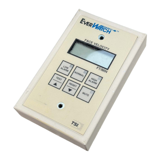
Operator Panel The EverWatch Face Velocity Monitor is easy to use. All the information you need to know about the face velocity is displayed on the monitor's front panel. In addition, all configuration and calibration programming is accessible through the keypad. Specific details about the EverWatch monitor front panel display and controls are described on the following pages. -
Page 9: Alarms
HIGH ALARM Light/Key The red high alarm light turns on when the face velocity exceeds the high face velocity alarm set point (green normal light goes off). The HIGH ALARM key, when pressed, displays the high alarm set point on the digital display. -
Page 10: Before Calling Tsi
Before Calling TSI The manual should answer most questions and resolve most problems you may encounter. If you need assistance or further explanation, contact your local TSI representative or TSI. TSI is committed to providing high quality products backed by outstanding service. -
Page 11: Part Two
PART TWO Technical Section The EverWatch monitor is ready to use after being properly installed and calibrated. The monitor is programmed with a default configuration that can be easily modified to fit you application. The “Technical” section is separated into five parts that cover all aspects of the units. Each section is written as independently as possible to minimize flipping back and forth through the manual for an answer. -
Page 12: Software Programming
Software Programming The EverWatch monitor is a quick and easy to program. There are two menus that contain all the items that can be changed. The configuration menu changes items that enhance the monitor’s performance (i.e., alarm values, display averaging, etc.). The calibration menu has the menu items needed to properly calibrate the EverWatch monitor. - Page 13 Figure 2: Programming Flow Chart Programming Example The following example demonstrates the programming keystroke sequence. In this example the face velocity low alarm will be programmed for 60 ft/min. 1. Press the NORMAL key to access the main menu. CAL will be indicated on the display.
-
Page 14: Menu And Menu Items
4. Press the NORMAL key to select LAL (low alarm menu item). The current value will be displayed. 5. Press the arrow keys ▲/▼ to change the item value to 60. 6. Press the NORMAL key to save the value and to exit to the menu. LAL will be displayed. - Page 15 CALIBRATION MENU MENU ITEM SOFTWARE ITEM DESCRIPTION ITEM RANGE DEFAULT NAME VALUE CALIBRATION LCAL The velocity CALIBRATION ZERO item is used to calibrate the NONE Unit needs to ZERO EverWatch velocity sensor at zero flow. be calibrated. No default A sensor zero should be established prior to adjusting the value exists.
- Page 16 CONFIGURATION MENU MENU ITEM SOFTWARE ITEM DESCRIPTION ITEM RANGE DEFAULT NAME VALUE LOW ALARM L_AL The LOW ALARM item sets the low face velocity alarm Off, 5 to 1000 ft/min setpoint. A low alarm condition is defined as when the face velocity falls below the low alarm setpoint.
- Page 17 ALARM DSBL The dSBL item selects whether the audible alarm can be On or Off DISABLE permanently muted (on) or cannot (off) by pressing the MUTE key (yellow light on). ANALOG AOUt The AOut item is used to select the type of analog output. The 0 to 10 volt (VOLt) VoLt OUTPUT...
- Page 18 CALIBRATION The End item identifies that the end of the calibration menu has NONE This is not a MENU END been reached. menu item. This identifies that the end of the menu has been reached.
-
Page 19: Calibration
Calibration The EverWatch Face Velocity Monitor is a very versatile device which will work with a variety of fume hoods. Because fume hoods vary in design and performance, the EverWatch monitor must be calibrated on the fume hood it is installed. The calibration procedure is quite simple and can be accomplished in a matter of minutes with a little preparation and practice. - Page 20 Note 2: If the sensor has not been taped, "tAPE OVEr SEn SOr" ("tape over sensor") will be indicated on the display. This message will flash for approximately two minutes. If the sensor has not been taped by the end of this time period, the calibration menu is exited and the EVERWATCH monitor returns to normal operation.
-
Page 21: Maintenance And Repair Parts
Maintenance and Repair Parts The EverWatch monitor is almost maintenance free. An occasional sensor cleaning and periodic calibration checks are all that are needed to ensure that the EverWatch monitor is operating at optimum performance. Calibration EverWatch monitor should be calibrated annually. Refer to “Calibration” section instructions. The velocity sensor should be cleaned prior to calibration. - Page 22 Troubleshooting Symptom Possible Cause Corrective Action Display is blank. Fuse is blown. Measure voltage at pins 1 and 2 on monitor. The voltage should nominally be 24 to 30 VAC. If correct voltage is measured, internal monitor fuse is probably blown. Unplug 10-pin connector from monitor for 2 minutes.
- Page 23 Symptom Possible Cause Corrective Action The display does Velocity sensor. Check velocity sensor location. Make sure it matches not indicate zero installation instructions. The sensor should directly at zero flow. reference room air. If required, mount a fume hood vent kit.
- Page 24 Symptom Possible Cause Corrective Action Monitor does not Network protocol Go into CONFIGURE menu, RS-485 type item. The respond to RS- is incorrect. protocol must match host system. Select correct interface. communications. Incorrect network address. The network address at the building automation system and at the monitor must match.
-
Page 25: Specifications
APPENDIX A Specifications Model 8610 Model 8610 English Units Metric Units Face Velocity Display Range ......... 0 to 1000 ft/min 0 to 5.00 m/s (displays to 1500) (displays to 7.60) Resolution ........5 ft/min 0.02 m/s Accuracy ........±10% or ±10 ft/min ±10% or ±0.05 m/s (at calibrated position) .... -
Page 26: Network Communications
Appendix B Network Communications Network communications are available on the Model 8610. The Model 8610 can communicate with a building management system through Modbus protocol. Please refer to the appropriate section below for more detailed information. Modbus Communications Modbus communications are installed in the Model 8610 fume hood face velocity monitors. - Page 27 8610 Fume Hood Monitor Variable Information Provided to Integer DDC System Variable Name Address Master System Receives Model Number Model Number 8610 Face Velocity Fume Hood Face Velocity Displayed in ft/min. Status Index Status of EverWatch device 0 Normal 1 Low Alarm 2 High Alarm 3 Sensor Error 5 Data Error...
-
Page 28: Wiring Information
APPENDIX C Wiring Information Back Panel Wiring Input / Output / PIN # Communication Description J1 Terminal Strip 1, 2 Input 24 VAC/VDC to power Digital Interface Module (DIM). NOTE: 24 VAC becomes polarized when connected to DIM. 3, 4 Output High alarm relay - N.O., closes in low alarm condition. -
Page 29: Wiring Diagram
Wiring Diagram Wiring Information... -
Page 30: Start-Up Report
APPENDIX D Start-up Report The next page shows a typical start-up report for a Model 8610 Fume Hood Face Velocity Monitor. It can be duplicated for use during calibration for documentation. Appendix D... - Page 31 Fume Hood Monitor Report Hood Number and/or Location: □ □ 8610 Model #: Vent Kit: Traverse: (Face velocity information as left and in accordance with ASHRAE 110) Sash position: inches above work surface Minimum / Average / Maximum: __________ / __________ / __________ feet/minute Displayed Face Velocity: Sash full open Sash stop...
-
Page 32: Access Codes
APPENDIX E Access Codes These are the access codes to the calibration and configuration menus. When an access code is required, pressing the following key sequence will provide access to the required menu. Key # Calibration Configuration RESET LOW ALARM LOW ALARM TEST NORMAL... - Page 33 TSI Incorporated – Visit our website www.tsi.com for more information. Tel: +1 800 874 2811 India Tel: +91 80 67877200 Tel: +44 149 4 459200 China Tel: +86 10 8251 6588 France Tel: +33 4 91 11 87 64 Singapore Tel: +65 6595 6388 Germany Tel: +49 241 523030...
Need help?
Do you have a question about the EVERWATCH 8610 and is the answer not in the manual?
Questions and answers