
Related Manuals for TSI Instruments SidePak AM520


Summary of Contents for TSI Instruments SidePak AM520
- Page 1 ™ SidePak Personal Aerosol Monitor Model AM520/AM520i User Guide P/N 6009829 Rev. N April 2022 www.tsi.com...
- Page 2 Start Seeing the Benefits of Registering Today! ® ® Thank you for your TSI instrument purchase. Occasionally, TSI releases information on software updates, product enhancements and ® new products. By registering your instrument, TSI will be able to send this important information to you. http://register.tsi.com As part of the registration process, you will be asked for your comments on TSI products and services.
- Page 3 90 days from the date of shipment; b. SidePak AM520/AM520i internal pump and battery are warranted for one (1) year from the date of manufacture. c. Parts repaired or replaced as a result of repair services are warranted to be free from defects in workmanship and material, under normal use, for 90 days from the date of shipment;...
- Page 4 REPAIR OR REPLACEMENT OF THE GOODS. IN THE CASE OF SOFTWARE, SELLER WILL REPAIR OR REPLACE DEFECTIVE SOFTWARE OR IF UNABLE TO DO SO, WILL REFUND THE PURCHASE PRICE OF THE SOFTWARE. IN NO EVENT SHALL SELLER BE LIABLE FOR LOST PROFITS, BUSINESS INTERRUPTION, OR ANY SPECIAL, INDIRECT, CONSEQUENTIAL OR INCIDENTAL DAMAGES.
-
Page 5: Table Of Contents
CONTENTS SAFETY INFORMATION ..............IX Intrinsic Safety Rating Information (AM520i only) ......xi Instructions Specific to Hazardous Area Installations ..... xiii Additional information ..............xv Intended Use—AM520i ..............xv Intended Use—AM520 ..............xv IECEx (Sira, Issued 2018), IECEx (SIMTARS, Issued 2019) ..xv ATEX (Sira 18ATEX2150X, Issued 2018) ........ - Page 6 Settings ................... 23 Enabling the Response Concentration ........23 Setting the Log Interval ..............24 Setting the Time Constant ............25 Setting the Time and Date and Date Format ....... 28 Measurement Units ..............30 Battery Units ................30 Screen Save Delay ..............30 Language ..................
- Page 7 APPENDIX B CUSTOM CALIBRATIONS ........67 Developing a Photometric Calibration Factor for a Spe cific Aerosol ................. 68 Photometric Calibration Factor Procedure ........69 Determining the Response Factor for a Specific Aerosol ....70 Using TrakPro™ Data Analysis Software to Update User Calibration Factors ..............
- Page 8 (This page intentionally left blank) viii...
-
Page 9: Safety Information
Safety Information When operated according to the manufacturer’s instructions, this device is a Class I laser product as defined by U.S. Department of Health and Human Services standards under the Radiation Control for Health and Safety Act of 1968. A certification and identification label similar to the one shown below is affixed to each instrument. - Page 10 W A R N I N G S • INTRINSICALLY SAFE (AM520i only) • THE EFFECT OF THE INTERNAL LASER ON GAS MIXTURES HAS NOT BEEN EVALUATED BY CSA • EXPLOSION HAZARD – SUBSTITUTION OF COMPONENTS MAY IMPAIR INTRINSIC SAFETY W A R N I N G S •...
-
Page 11: Intrinsic Safety Rating Information (Am520I Only)
label on the intrinsic safety rating label directs you to read all the warnings in the manual. Intrinsic Safety Rating Information (AM520i only) CLASS 2258-03 PROCESS CONTROL EQUIPMENT – Intrinsically Safe and Non-Incendive Systems - For Hazardous Locations – Certified to Canadian Standards Class I, Division I, Groups A, B, C, D, Class II, Division I, Groups E, F, G, Class III;... - Page 12 W A R N I N G Any damage to the base unit that results in a cracked or broken ® case should be immediately returned to TSI for repair as it may affect safety rating compliance of the equipment. A damaged case could allow for the ingress of dust, dirt or other material and moisture into the unit and diminish the safety of the device.
-
Page 13: Instructions Specific To Hazardous Area Installations
W A R N I N G • DO NOT ATTEMPT TO CONNECT THE USB INTERFACE IN A HAZARDOUS AREA • DO NOT OPEN WHEN AN EXPLOSIVE ATMOSPHERE IS PRESENT • EXPLOSION HAZARD – SUBSTITUTION OF COMPONENTS MAY IMPAIR INTRINSIC SAFETY •... - Page 14 4. The maximum surface temperature of the AM520i is 143.8°C 5. The equipment is only certified for use in ambient temperatures in the range 0°C to +50°C and should not be used outside this range. 6. Installation shall be carried out in accordance with the applicable code of practice by suitably-trained personnel.
-
Page 15: Additional Information
The AM520i shall only be charged in the non-hazardous area using the charger specifically supplied for use with the unit approved as SELV (or Class 2, for North America) equipment against IEC 60950. The maximum output voltage from the charger shall not exceed 12 VDC. The battery pack assembly model number 803322 shall only be removed or replaced in the non-hazardous area. -
Page 16: North America (Can/Us, Issued 2018)
North America (CAN/US, Issued 2018) • CAN/CSA-C22.2 No. 61010-1-12 (reaffirmed 2017): Safety requirements for electrical equipment for measurement, control, and laboratory use - Part 1: General requirements – Third Edition; Update No. 1: July 2015; Update No. 2: April 2016 •... -
Page 17: Chapter 1 Unpacking And Parts Identification
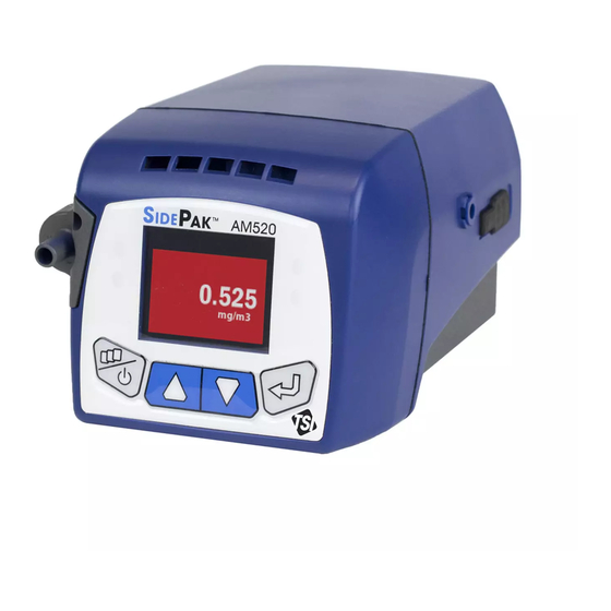
Chapter 1 Unpacking and Parts Identification Carefully unpack the AM520/AM520i SidePak™ Personal Aerosol Monitor from the shipping container. Use the table below to identify the components that are included with the unit. A photo and description of ® each item follows the table. If any parts are missing, contact TSI immediately. - Page 18 Part/Order Item Description Number Reference Picture AM520 Personal Aerosol AM520 Monitor (shown with battery pack) AM520i Personal AM520i Aerosol Monitor (shown with battery pack) AM520 Battery Pack, 803300 or 5100 mAH 803322 AM520 / AM520i Battery 803322 Pack, 5100 mAH for use in either product Single Carry Case 803313...
- Page 19 Part/Order Item Description Number Reference Picture Impactor Kit 803301 (impactor oil, impactor disc (3x), Blank inlet, inlet, PM inlet, inlet, PM inlet. 6 ea. inlet gaskets) PM2.5 Impactor Kit 803312 Dorr-Oliver 10-mm Nylon 801701 Cyclone Kit DPM Cyclone Kit 803303 Calibration Jar, 1 liter 803310 (accessory sold...
- Page 20 Part/Order Item Description Number Reference Picture AM520/AM520i Field 803306 Service Kit (includes: 3 ea. USB Dust Plugs / 3 ea. Impactor Disks / 6 ea. Impactor Gaskets Zero Filter 800663 AM520/AM520i Power 803302 Supply with Universal Plug Set USB Cable 803305 ®...
- Page 21 Part/Order Item Description Number Reference Picture AM520/AM520i 6009829 User Guide Quick Start Guide and 6009830 Keypad Functions SidePak™ 6009831 AM520/AM520i Personal Aerosol Monitor Li-Ion Battery Maintenance Card Unpacking and Parts Identification...
- Page 22 (This page intentionally left blank) Chapter 1...
-
Page 23: Chapter 2 Setting Up
Chapter 2 Setting Up Supplying Power to the SidePak™ Aerosol Monitor Attach the rechargeable battery pack to the AM520/AM520i. Initially the Lithium Ion rechargeable battery pack will need to be plugged into the AC adapter (power supply) and plugged into a mains power outlet before use. -
Page 24: Installing The Lithium Ion Battery Pack
Installing the Lithium Ion Battery Pack 1. Place the battery pack under the AM520/AM520i. 2. Push firmly to slide into place. 3. Fasten it in place using the two battery screws provided. Chapter 2... -
Page 25: Removing The Lithium Ion Battery Pack
Removing the Lithium Ion Battery Pack 1. To remove battery, remove battery screws. 2. Firmly grip sides of instrument and sides of battery. 3. Pull apart. Smart Battery Management System™ Technology The rechargeable Lithium Ion battery pack is designed with Smart Battery Management System™... -
Page 26: Storing The Battery Pack Between Uses
® recommends fully charging the battery before first use of a new instrument. The battery can be charged when not installed in the instrument. Accordingly, a second battery (purchased as an accessory) can be charged on its own using the AC adapter supplied with the AM520/AM520i, while the equipment is in use with another ®... -
Page 27: Using The Ac Adapter (Power Supply)
W A R N I N G Remove Li-ion battery during storage and transportation of instrument. Using the AC Adapter (power supply) The AC adapter powers the AM520/AM520i from an AC wall outlet, and charges the rechargeable battery pack. The AC adapter can run the instrument and charge the battery at the same time. -
Page 28: Battery Icon On Display
Battery Icon on Display When the battery is charging, the battery icon on the instrument display repeatedly flashes a pattern with increasing numbers of segments. When charging is complete, the icon indicates a full charge. A full battery icon means at least 10 hours of battery life is available. -
Page 29: Chapter 3 Operation
Chapter 3 Operation Overview The SidePak™ Personal Aerosol Monitor is a miniature battery- operated laser photometer that measures aerosol (airborne particle) mass concentration in units of milligrams or micrograms per cubic meter (mg/m or µg/m The built-in sampling pump flow rate is user-adjustable; giving the user the flexibility to attach a wide variety of inlet conditioners to sample from the worker’s breathing zone or other locations. -
Page 30: Power Port
Power Port Connect the power supply to ® this port to charge the TSI battery pack or to power the instrument at any time. NO T IC E Many power supplies look alike. Use the proper power supply to prevent damage. NO T IC E After charging the battery, close/seal the AC power port with the attached AC dust plug. -
Page 31: Battery Screws
Battery Screws Remove these two screws to remove the battery. Operation... -
Page 32: Keypad Functions
Keypad Functions To turn the instrument ON, press the ESC-ON/OFF key. To turn the instrument OFF, press and hold the ESC-ON/OFF key for three (3) seconds (release key when the countdown reaches "0 SECONDS." The model number, serial number, and firmware revision are displayed for a few seconds before entering Survey Mode. -
Page 33: Main Menu
Main Menu The menu structure of the SidePak™ monitor is very easy to use. The graphic below shows the menu structure from the Main Menu. After power up, the instrument will be in Survey Mode as indicated by the From the Main Menu, use the ▲ ▼ keys to select one of the following category menus and then press the ... -
Page 34: Power Up
Refer to the sections below for details on each of the sub-menu items under each category. Power Up Turn the instrument on by pressing the ESC- ON/OFF key. The instrument displays the ® logo followed by the model number, serial number, and firmware version. -
Page 35: Data Logging
Use the ▲ ▼ keys to scroll down/up the Survey mode menu to view menu items that are off screen. When the monitor is in Survey screen saver mode, the title “Survey” and the battery icon are briefly displayed and will disappear after a few seconds. - Page 36 If the instrument is programmed to wait before logging, it will show a “PROG DELAY” screen with the current time/date and the programmed start time/date. If the starting time/date is more than one minute in the future, the instrument will turn off the pump and laser in order to save power.
-
Page 37: Run Mode
The screen saver briefly displays the title “Logging Data” and shows the battery icon. These disappear after a few seconds to save power. Real-time concentration measurements are shown at a random screen location. When the screen saver is active, the keys can be ▲... -
Page 38: Program Mode
Press or ESC to stop a test in progress. The instrument will ask to confirm to stop the test or not, while data logging continues. If ESC is pressed to continue, there will be no break in the logged data. Program Mode Prog 1 …Prog 5 activates a data logging test that has been preprogrammed using TrakPro™... -
Page 39: Settings
Settings Access the SETTINGS menu from the MAIN MENU, then use the ▼ key to select SETTINGS and press (ENTER). The SETTINGS menu provides access to the following items. Use the ▲ ▼ keys to select the item you want to access and press ... -
Page 40: Setting The Log Interval
Setting the Log Interval The LOG INTERVAL is the time interval used between recorded data points during Manual Mode logging operations (log intervals for Prog-1 through Prog-5 are set using TrakPro™ Software). For example, if the LOG INTERVAL is set to 30 seconds, a data point is stored to memory once every 30 seconds. -
Page 41: Setting The Time Constant
After selecting Log Interval from the Setup Menu, the display will show LOG INTVLx where "x" is a number from 1 to 5. This is the currently selected log interval. The value of that log interval is shown on the second line. Use the ▲... - Page 42 After selecting TIME CONSTANT from the SETTINGS menu, the display will show Time Constant x where "x" is a number from 1 to 5. This is the currently active Time Constant. The value of that Time Constant is shown on the second line. Use the ▲...
- Page 43 Log Interval vs. Time Constant • The LOG INTERVAL is the time interval used between recorded data points. It can be set using the SETTINGS menu and in Program logging mode using TrakPro™ software. • The AM520/AM520i always takes a measurement once every second regardless of the Log Interval.
-
Page 44: Setting The Time And Date And Date Format
Setting the Time and Date and Date Format Set the Date Format The date format is user-selectable. The formats available are: • yyyy/mm/dd (default) • mm/dd/yyyy • dd/mm/yyyy where yyyy is the 4-digit year, mm is the 2-digit month, and dd is the 2-digit day of month. - Page 45 Set the Current Time 1. Select SETTINGS from the MAIN MENU with the ▲ ▼ keys and press (ENTER). 2. Under SETTINGS MENU, select TIME/DATE with the ▲ ▼ keys and press ENTE (ENTER). 3. Under the TIME/DATE menu, use the ▲ ▼ keys to select the time.
-
Page 46: Measurement Units
Measurement Units 1. Select SETTINGS from the MAIN MENU with the ▲ ▼ keys and press (ENTER). 2. Under SETTINGS menu, select MEAS UNITS with the ▲ ▼ keys and press (ENTER). . Press (ENTER) to 3. Use the ▲ ▼ keys to select mg/m or µg/m accept. -
Page 47: Language
Language The display language can be changed to English (default) or Chinese. To set the language: 1. Select SETTINGS from the MAIN MENU with the ▲ ▼ keys and press (ENTER). 2. Under SETTINGS menu, select Language with the ▲ ▼ keys and press ... - Page 48 Effect of Calibration Factors on Full Scale and Alarms • Note that the instrument maximum full scale mass concentration reading is not fixed at 100 mg/m³; it changes when the Photometric Calibration Factor is changed. The same is true with the Response Factor and response concentration reading.
-
Page 49: Zeroing The Instrument (Zero Cal)
There are three items on the Calibration menu. Zero Cal This activates a function which re-zeroes the measurement using a filter. Flow Cal This activates a function which allows you to set the pump voltage to achieve the desired sample flow. This allows you to select a User Cal photometric calibration... -
Page 50: Flow Cal
6. The instrument will count-down from 60 to 0 and display Zero Cal Complete. 7. Press the ESC key to return to the CALIBRATION menu. 8. The instrument is now ready to make accurate measurements. Flow Cal Aerosol concentration measurements with the SidePak™... -
Page 51: User Cal
5. Each single click of an ▲ ▼ key changes the flow by 1 percent of the available range. The flow rate can be changed more quickly by holding the arrow key down. The range is 0 to 200. 6. Press (ENTER) to accept the numerical flowrate change, the CALIBRATION MENU is now displayed. -
Page 52: Data
User Cal 3 to 12 default to a PCF of 1.00 and RF of 0.00% and can be adjusted and renamed through TrakPro™ software. User Cal 3 to 12 can also be changed in the field through the AM520/AM520i CALIBRATION MENU. After pressing ... -
Page 53: Clear Memory
5. If the display shows N/A for the TWA, it means that there is not enough data in that test to compute the TWA. The instrument must be operated for a minimum of 15 minutes before a valid TWA may be calculated. 6. - Page 54 A General Alarm (Mass or Response) is active during Survey mode and while data logging. If the displayed reading (based on Time Constant setting) exceeds the Alarm value, the alarm triggers. Depending on settings in the ALARMS MENU, the display will flash red or the LEDs on the membrane switch may flash or an audible beeper may sound.
-
Page 55: Post-Sampling Data Reporting And Graphing
To select an alarm and an alarm action: 1. Select ALARMS from the MAIN MENU with the ▲ ▼ keys and press (ENTER). The ALARMS menu has the following options: • • Mass Alarm LEDs • • Mass STEL Audible •... - Page 56 (This page intentionally left blank) Chapter 3...
-
Page 57: Chapter 4 Maintenance
Chapter 4 Maintenance The SidePak™ AM520/AM520i Personal Aerosol Monitor requires periodic maintenance. The most common procedures are: • General cleaning • Impactor maintenance • Cyclone maintenance • Charging batteries • Zeroing the Instrument ® In addition to the procedures in this chapter, TSI recommends that you return your SidePak™... -
Page 58: Using And Maintaining Built-In Impactors
Use a foam or lint-free swab to clean the alarm vents on the front of the unit. NO T IC E DO NOT use high pressure compressed air as this may harm the internal membrane of the alarm horn and re-aerosolize particulate matter. - Page 59 SidePak™ size-selective inlets are used with an internal impactor disk (provided). The impactor disk functions as a collection plate where particles larger than the cut-size are trapped. The same impactor disk is used for all impactors, but it is not used for the standard inlet. To make sure unwanted (large) particles remain trapped on the impactor disk, it is necessary to apply 1 to 4 drops of...
- Page 60 3. Clean the impactor inlet and impactor disk with a clean lint- free swab or microfiber cloth and light solvent. Gently blow impactor body dry with canned/pressurized clean air or allow to air dry. Use a lint-free swab or microfiber cloth to clean impactor well inside the instrument case to remove accumulated particles.
- Page 61 6. Place inlet gasket on the inlet so that the tabs on the gasket fit inside the inlet around inner tabs of the inlet as shown. 7. Place impactor inlet on instrument. 8. Secure the impactor assembly back onto the instrument body by tightening the two captive screws.
-
Page 62: Using And Maintaining The Respirable Cyclone
Using and Maintaining the Respirable Cyclone The 10-mm Nylon Dorr-Oliver Cyclone included with the AM520/AM520i can be used to differentiate between the respirable fraction and other portions of the ambient aerosol. It is ideal for making breathing zone measurements because it can be ®... -
Page 63: Cleaning The Cyclone
Cleaning the Cyclone The 10-mm Nylon Dorr-Oliver Cyclone should be cleaned prior to each use. In most cases, simply cleaning the grit potentiometer is all that is necessary. Inspect the inside of the cyclone body regularly and clean it if necessary. 1. -
Page 64: Using And Maintaining The Diesel Particulate Matter Dpm Cyclone
Using and Maintaining the Diesel Particulate Matter DPM Cyclone The DPM Cyclone included with the AM520/AM520i can be used to differentiate between the diesel particulate matter and other portions of the ambient aerosol. It is ideal for making breathing zone measurements because it can be attached to clothing near the ®... - Page 65 1. When using the cyclone, be sure that there is no impactor disk installed. Use the standard inlet (unmarked) with gasket. 2. Attach the Dorr-Oliver cyclone to the DPM cyclone to create the DPM assembly. 3. Attach the DPM cyclone assembly and sample tube onto the inlet.
-
Page 66: Cleaning The Diesel Particulate Matter Dpm Cyclone
Cleaning the Diesel Particulate Matter DPM Cyclone The DPM Cyclone should be cleaned prior to each use. In most cases, simply cleaning the grit potentiometer is all that is needed. Inspect the inside of the cyclone body regularly and clean it if necessary. 1. -
Page 67: Calibrating Of Measuring Dpm
NO T IC E When re-assembling the cyclone, fully seat the cap to maintain the proper flow rate. Failure to seat the cap may affect the particle cut- size of the cyclone. Calibrating of Measuring DPM ® The Zefon Cyclone Calibration Jar is a 1 liter container with all the proper fittings and connections needed to calibrate sampling pump flow rates with other... -
Page 68: Am520/Am520I Field Service Kit - Sold Separately
AM520/AM520i Field Service Kit – sold separately The SidePak™ AM520/AM520i Field Service Kit (P/N 803306) includes the following to replace damaged or lost items: Description USB Dust Plugs Impactor Plates Impactor Gaskets Chapter 4... -
Page 69: Chapter 5 Troubleshooting
Chapter 5 Troubleshooting ® recommends the SidePak™ Model AM520/AM520i Personal Aerosol Monitor be returned to the factory for annual calibration. Regular factory-authorized cleaning and recalibration helps ensure that the instrument is working properly, has the latest updates, and will provide accurate and reliable measurements. If you are having a problem with your SidePak™... -
Page 70: Troubleshooting Table
Troubleshooting Table Symptom Possible Cause Corrective Action Check all connections Erratic zero reading. Leak. for leaks. Carefully tighten sample inlet screws (DO NOT over-tighten!). If using an impactor, remove, clean and re-oil the impactor disc. Make sure the O-ring is in place and not damaged. - Page 71 Symptom Possible Cause Corrective Action Mass concentration Instrument has number is blinking reached the and stays on the calibrated limit of its same value. range (multiplied by Cal Factor). No keypad response. Keypad is locked out. To unlock the keypad, press and hold the ▲...
- Page 72 Symptom Possible Cause Corrective Action LOGGING STOPPED, User has discontinued NO DATA SAVED. data logging before a single data point was message is displayed. recorded. INVALID START TIME User is attempting to Setup logging protocol for run a data logging program logging using message is displayed.
- Page 73 Symptom Possible Cause Corrective Action Zero baseline on Perform a zero ZERO DRIFT instrument has calibration. See message is displayed. “Calibration, Zero drifted. This error Cal”, can be caused by in Chapter 3, for more zeroing with a dirty information. or leaking filter.
-
Page 74: Technical Contacts
Symptom Possible Cause Corrective Action Logged data may Download logged data to LOG DATA READ have been corrupted. TrakPro™ software (to save) then do CLEAR LOG DATA WRITE MEMORY to clear the error message is corrupt data. displayed. One of: Internal hardware If error recurs, return to fault. -
Page 75: International Contacts
International Contacts Service TSI Instruments Singapore Pte Ltd 150 Kampong Ampat #05-05 KA Centre Singapore 368324 Telephone: +65 6595-6388 Fax: +65 6595-6399 E-mail: tsi-singapore@tsi.com TSI Instrument (Beijing) Co., Ltd. Unit 1201, Pan-Pacific Plaza No. 12 A, Zhongguancun South Avenue Haidian District, Beijing, 100181... -
Page 76: Technical Support
Technical Support TSI Instruments Singapore Pte Ltd 150 Kampong Ampat #05-05 KA Centre Singapore 368324 Telephone: +65 6595-6388 Fax: +65 6595-6399 E-mail: tsi-singapore@tsi.com TSI Instrument (Beijing) Co., Ltd. Unit 1201, Pan-Pacific Plaza No. 12 A, Zhongguancun South Avenue Haidian District, Beijing, 100181... -
Page 77: Returning For Service
Returning for Service and complete the on-line “Service Visit our website at tsi.com/service Request” form or call TSI ® at 1-800-680-1220 (USA), (651) 490-2860, or 001 651 490-2860 (International) for specific return instructions. Customer Service will need the following information: •... - Page 78 (This page intentionally left blank) Chapter 5...
-
Page 79: Appendix A Specifications
Appendix A Specifications Specifications are subject to change without notice. Sensitivity Sensor type 90 light scattering, 650 nm laser diode Aerosol concentration 0.001 to 100 mg/m (calibrated to range respirable fraction of ISO 12103-1, A1 Test Dust) Particle size range 0.1 to 10 µm Minimum resolution 0.001 mg/m... - Page 80 Built-in Inlets Standard inlet Not size-specific impactor 50% cut-off at 1.0 µm impactor 50% cut-off at 2.5 µm impactor 50% cut-off at 5.0 µm impactor 50% cut-off at 10.0 µm Attachable Cyclones 4 µm Dorr-Oliver 50% cutoff at 4.0 µm 0.8 µm DPM 50% cut-off at 0.8 µm Alarms...
- Page 81 Physical External dimensions 5.1 x 3.7 x 3.1 inch (129.5 x 94 x 78.4 mm) with 803300, 803311, and 803322 battery Weight 22 oz. (0.62 kg) with 803300, 803311, and 803322 battery Display 160 x 128 resolution color OLED display Tripod socket ¼-20 female thread Battery...
- Page 82 Environmental/Installation Maximum altitude 2000 meters Pollution Degree Installation Category Approvals AM520 with TSI Battery Pack P/N 803300, 803311, and 803322 Immunity EN61326-1:2013 Emissions EN61326-1:2013 Class B IEC 61010-1:2010 Safety IEC 60825-1:2014 AM520i with TSI Battery Pack P/N 803322 Immunity EN61326-1:2013 Emissions EN61326-1:2013 Class B IEC 61010-1:2010...
-
Page 83: Appendix B Custom Calibrations
Appendix B Custom Calibrations In most situations, the Model AM520/AM520i provides very good information on how the concentration of an aerosol changes for over time. Factory calibration to the respirable fraction of standard ISO 12103-1, A1 Test Dust (aka, Arizona Test Dust) allows comparisons between measurements where the source or type of dust is predominately the same. -
Page 84: Developing A Photometric Calibration Factor For A Specific Aerosol
All of these options require that a true mass concentration (via gravimetric analysis) is determined for the aerosol measured. The true mass concentration is used to calculate the Photometric Calibration Factor for that aerosol. Further lab analysis of the sample is required to determine what percentage of the sample represents the specific substance of interest. -
Page 85: Photometric Calibration Factor Procedure
Photometric Calibration Factor Procedure 1. Set up photometer and sampling pump in similar manner. • SidePak™ AM520/AM520i (with Dorr-Oliver Cyclone if measuring respirable size fraction). • Sample pump with a sampling cassette (with Dorr-Oliver Cyclone if measuring respirable size fraction). 2. -
Page 86: Determining The Response Factor For A Specific Aerosol
PCF= Photometric Calibration Factor Reference Concentration = Average Gravimetric Concentration Data Log Concentration = Average Photometric Concentration = Existing Calibration Factor (by default Factory calibration is 1.0) ������������������ �������������������������� ������ = × ������ �������� ������ �������������������������� 10. Enter new Photometric Calibration Factor into the photometer. 11. -
Page 87: Using Trakpro™ Data Analysis Software To Update User Calibration Factors
The Response Factor is determined from the same gravimetric sample taken to determine the PCF. That gravimetric sample should be further analyzed using an appropriate method in order to determine what percentage of the total sampled dust consists of a particular hazard. - Page 88 (This page intentionally left blank) Appendix B...
-
Page 89: Appendix C Converting Stored Data To Calibrated Data
Appendix C Converting Stored Data to Calibrated Data A single set of logged data can be converted to data calibrated to a specific aerosol with the use of the TrakPro™ Data Analysis Software. This conversion can be done by knowing either the true mass concentration for the logged data or the calibration factor for the aerosol. - Page 90 (This page intentionally left blank) Appendix C...
-
Page 91: Appendix D Csa Certificate Of Compliance
Appendix D CSA Certificate of Compliance ® Certificates of Compliance on file at TSI... -
Page 92: Am520 Declaration Of Conformity
AM520 Declaration of Conformity Appendix D... - Page 93 CSA Certificate of Compliance...
-
Page 94: Am520I Declaration Of Conformity
AM520i Declaration of Conformity Appendix D... - Page 95 CSA Certificate of Compliance...
- Page 96 (This page intentionally left blank) Appendix D...
- Page 98 TSI Incorporated – Visit our website www.tsi.com for more information. Tel: +1 800 680 1220 India Tel: +91 80 67877200 Tel: +44 149 4 459200 China Tel: +86 10 8219 7688 France Tel: +33 1 41 19 21 99 Singapore Tel: +65 6595 6388 Germany Tel: +49 241 523030 P/N 6009829 Rev N ©2022 TSI Incorporated...
Need help?
Do you have a question about the SidePak AM520 and is the answer not in the manual?
Questions and answers