Advertisement
Table of Contents
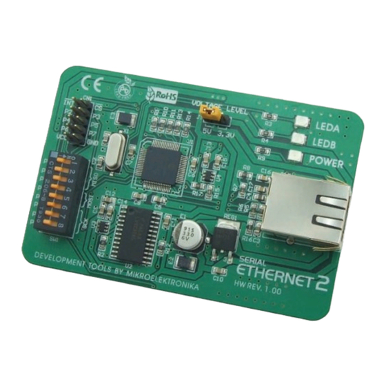
Serial Ethernet2
™
Manual
All Mikroelektronika's development systems feature a large number of peripheral
modules expanding microcontroller's range of application and making the
process of program testing easier. In addition to these modules, it is also
possible to use numerous additional modules linked to the development system
through the I/O port connectors. Some of these additional modules can operate
as stand-alone devices without being connected to the microcontroller.
MikroElektronika
Advertisement
Table of Contents

Subscribe to Our Youtube Channel
Related Manuals for mikroElektronika Series Ethernet2


Summary of Contents for mikroElektronika Series Ethernet2
- Page 1 Serial Ethernet2 ™ Manual All Mikroelektronika’s development systems feature a large number of peripheral modules expanding microcontroller’s range of application and making the process of program testing easier. In addition to these modules, it is also possible to use numerous additional modules linked to the development system through the I/O port connectors.
- Page 2 How to connect the board? The Serial Ethernet2 board can be easily connected to a development system via a 2x5 connector CN1. This connector is connected to a development system port that is used for serial SPI communication. Depending on the development system in use, it is necessary to set the appropriate switch on the DIP switch SW1 to the ON position, table 1.
- Page 3 EasyPIC, EasyLV-18F, LV18F, BigPIC EasyPIC, EasyLV-18F, LV18F, Easy 24-33, BigPIC, EasyAVR, Easy8051 Easy dsPIC EasyAVR, Easy8051 EasyAVR, Easy8051 Position of switches on DIP switch SW1 for appropriate development system Table 1 Figure 2: Dimensions of the Serial Ethernet2 additional board MikroElektronika...
- Page 4 Figure 3: Serial Ethernet2 board connection schematic MikroElektronika...
- Page 5 Figure 4: Serial Ethernet2 connected to a development system MikroElektronika...
- Page 6 MikroElektronika...
Need help?
Do you have a question about the Series Ethernet2 and is the answer not in the manual?
Questions and answers