Advertisement
™
Manual
All Mikroelektronika's development systems feature a large number of peripheral
modules expanding microcontroller's range of application and making the
process of program testing easier. In addition to these modules, it is also
possible to use numerous additional modules linked to the development system
through the I/O port connectors. Some of these additional modules can operate
as stand-alone devices without being connected to the microcontroller.
MikroElektronika
Advertisement
Table of Contents

Subscribe to Our Youtube Channel
Related Manuals for mikroElektronika Keypad 4x4


Summary of Contents for mikroElektronika Keypad 4x4
- Page 1 Keypad 4x4 ™ Manual All Mikroelektronika’s development systems feature a large number of peripheral modules expanding microcontroller’s range of application and making the process of program testing easier. In addition to these modules, it is also possible to use numerous additional modules linked to the development system through the I/O port connectors.
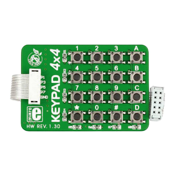
- Page 2 Keypad 4x4 Keypad 4x4 is used for loading numerics into the microcontroller. It consists of 16 buttons arranged in a form of an array containig four lines and four columns. It is connected to the development system by regular IDC 10 female connector plugged in some development system’s port.
- Page 3 Keypad 4x4 Figure 4: Keypad, LCD and microcontroller connection schematic Example 1: Program written in mikroC PRO for PIC unsigned short kp, cnt, oldstate = 0; case 1: kp = 49; break; // 1 // Uncomment this block for keypad4x4 char txt[6];...
- Page 4 Keypad 4x4 Example 2: Program written in mikroBasic PRO for PIC program Keypad_Test case 1 dim kp, cnt, oldstate as byte kp = 49 ‘ 1 ‘ Uncomment this block for keypad4x4 txt as char[7] case 2 kp = 50 ‘ 2 ‘...
- Page 5 Keypad 4x4 Example 3: Program written in mikroPascal PRO for PIC program Keypad_Test; 1: kp := 49; // 1 // Uncomment this block for keypad4x4 2: kp := 50; // 2 var kp, cnt, oldstate : byte; 3: kp := 51; // 3 txt : array[6] of byte;...
Need help?
Do you have a question about the Keypad 4x4 and is the answer not in the manual?
Questions and answers