Table of Contents
Advertisement
Quick Links
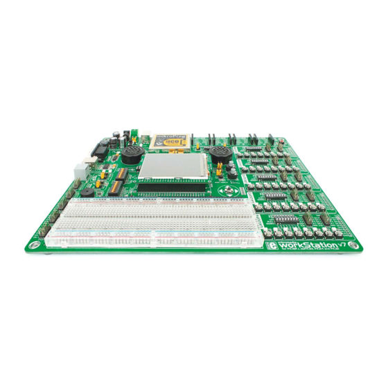
workStation
mikromedia
6 mikromedia boards supported
PIC18FJ
®
,dsPIC33
®
/PIC24
®
and PIC32
®
for PIC18FJ
Many on-board modules
Easy-add extra boards
Multimedia peripherals
mikroBUS™ sockets
, dsPIC33
, PIC24
and PIC32
®
®
®
Four connectors for each port
Amazing Connectivity
v7
®
Fast USB 2.0 programmer and
In-Circuit Debugger
Advertisement
Table of Contents

Subscribe to Our Youtube Channel
Related Manuals for mikroElektronika multimedia workStation v7


Summary of Contents for mikroElektronika multimedia workStation v7
- Page 1 workStation mikromedia for PIC18FJ , dsPIC33 , PIC24 and PIC32 ® ® ® ® 6 mikromedia boards supported Many on-board modules Easy-add extra boards Four connectors for each port Fast USB 2.0 programmer and PIC18FJ ® ,dsPIC33 ® /PIC24 ® and PIC32 ®...
- Page 2 Switching from one mikromedia to another while using virtually the same code is a very powerful concept. We are confident this will be especially interesting in education and among developers who need flexibility and rapid prototyping. Nebojsa Matic, Owner and General Manager of mikroElektronika...
-
Page 3: Table Of Contents
Introduction Connectivity Input/Output Group ....... Introduction ........mikroBUS sockets . -
Page 4: Introduction
Introduction After several years of successful production of mikromedia boards, ™ we have decided to delight users of our products and make a new development system that expands functionality of all mikromedia ™ boards with Microchip microcontrollers. The idea was to make a ®... -
Page 5: It's Good To Know
® 20122011 www.mikroe.com Copyright ©2011 Mikroelektronika. All rights reserved. Mikroelektronika, Mikroelektronika logo and other Mikroelektronika trademarks are the property of Mikroelektronika. All other trademarks are the property of their respective owners. Unauthorized copying, hiring, renting, public performance and broadcasting of this DVD prohibited. -
Page 6: Power Supply
Power supply Board contains switching power supply that creates stable voltage and current levels necessary for powering each part of board. Power supply section contains specialized MC33269DT3.3 power regulator which creates VCC-3.3V power supply, thus making the board capable of supporting 3.3V microcontrollers. -
Page 7: How To Power The Board
Power supply: via DC connector or screw terminals (7V to 23V AC or 9V to 32V DC), Board power supply creates stable 3.3V necessary for or via USB cable (5V DC) operation of the microcontroller and all on-board modules. Power capacity: up to 500mA with USB, and up to 600mA with external power supply How to power the board? -
Page 8: Mikromedia ™ Board Socket
mikromedia board socket ™ mikromedia workStation v7 contains four female headers that together form a socket for specialized ™ small development boards with a microcontroller and on-chip modules, called mikromedia boards. Two of ™ Figure 4-1: mikromedia ™ them are used for general purpose I/O and power pins (1x26). The other two are used for the mikroProg ™... - Page 9 VCC-5V MCU-VPP ANALOG 3.3V MCU-PGD MCU-PGC mikromedia 3.3V MCU-PGC MCU-PGD MCU-VPP for PICI8FJ, dsPIC33,PIC24 and PIC32 DATA BUS Figure 4-2: mikromedia board socket schematic ™ page 9...
-
Page 10: How To Properly Place Into The Socket
How to properly place your mikromedia board into the socket? ™ Before you plug the mikromedia board into the mikromedia workStation v7 board socket. Place the socket (make sure you don't push the screen). Check ™ ™ socket, make sure that the power supply is turned mikromedia board over the socket so that each male again if everything is placed correctly and press the... -
Page 11: What Is Mikromedia ™ Board
What is mikromedia board? ™ mikromedia board is a compact development different colors), battery charger, accelerometer, microSD USB MINI-B cable or battery supply. When you put any of ™ system with lots of on-board peripherals which allow card slot and 8 Mbit flash memory. mikromedia board also them in mikromedia... -
Page 12: Which One To Use
Which one to use? mikromedia for PIC18FJ mikromedia for PIC24 mikromedia for PIC24EP Architecture: 8-bit Architecture: 16-bit Architecture: 16-bit CPU speed: 12 MIPS CPU speed: 16 MIPS CPU speed: 70 MIPS Flash memory: 128 kB Flash memory: 256 kB Flash memory: 512 kB 3,904 Bytes 16 kB... - Page 13 For now we are giving you the choice to choose between 6 mikromedia boards. Each of them is specific in its own way. The main idea here is to show you comparative key features in one place, which makes it easier for you to choose. mikromedia for dsPIC33 mikromedia for dsPIC33EP mikromedia for PIC32...
-
Page 14: Bsp Makes Programming Easier
BSP package and mikromedia workStation v7 offers you be used with Mikroelektronika compilers. If you use other ™ unique set of markings on a silk screen which enables you the possibility to use this pin with the unique name G0.0,... - Page 15 Install board support package (BSP) in 3 simple steps: 1. Download package from libstock website 2. Install it with Package manager software 3. Use it as a library in mikroE compilers LOUT LOUT LOUT ROUT ROUT ROUT G0.0 G2.4 G0.0 G2.4 G0.0 G2.4...
-
Page 16: Package Manager
DVD:\\download\eng\software\compilers\package-manager\ package_manager_v240.zip Copyright ©2011 Mikroelektronika. All rights reserved. Mikroelektronika, Mikroelektronika logo and other Mikroelektronika trademarks are the property of Mikroelektronika. All other trademarks are the property of their respective owners. After downloading, extract the package and double click the Unauthorized copying, hiring, renting, public performance and broadcasting of this DVD prohibited. -
Page 17: Installing Bsp Libraries
The installation process is complete when the "Finished successfully" massage appears in Information section, Figure 4-8. Open the appropriate Mikroelektronika Compiler and in the "Library Manager" section (at the end of the list) you will see unmarked "mikromedia Workstation" library. -
Page 18: On-Board Programmer
On-board programmer What is mikroProg ™ mikroProg is a fast USB 2.0 programmer with mikroICD hardware ™ ™ In-Circuit Debugger. Smart engineering allows mikroProg ™ support all PIC10, PIC12, PIC16, PIC18, PIC24, dsPIC30/33, PIC32 MCU families in a single programmer! It supports over 570 microcontrollers from Microchip®. - Page 19 LINK ACTIVE DATA VCC-3.3V VCC-3.3V VCC-5V VCC-USB LED-DATA LED-DATA VCC- USB LED-ACT LED-ACT LED-USB USBDN-CON LED-USB USBDN- CON USBDP-CON USBDP -CON VCC-3.3V VCC-3.3V VCC-5V 100nF 100nF MCLR# MCL R# MCU-VPP VCC- 5V MCU- VP P VCC-3.3V MCU-PGC VCC- 3.3V MCU- PGC MCU-PGD MCU- PGD VCC-3.3V...
-
Page 20: Installing Programmer Drivers
Copyright ©2011 Mikroelektronika. All rights reserved. Mikroelektronika, Mikroelektronika logo and other Mikroelektronika trademarks are the property of Mikroelektronika. All other trademarks are the property of their respective owners. Unauthorized copying, hiring, renting, public performance and broadcasting of this DVD prohibited. -
Page 21: Programming Software
After downloading, extract the package and double click the Copyright ©2011 Mikroelektronika. All rights reserved. Mikroelektronika, Mikroelektronika logo and other Mikroelektronika trademarks are the property of Mikroelektronika. All other trademarks are the property of their respective owners. Unauthorized copying, hiring, renting, public performance and executable setup file, to start installation. -
Page 22: Mikroicd™ - In Circuit Debugger
™ tools on the market. Supported Compilers All MikroElektronika compilers, mikroC, mikroBasic and mikroPascal for PIC®, dsPIC® and PIC32® natively support mikroICD . Specialized mikroICD DLL module allows compilers to ™... - Page 23 ™ Here is a short overview of which debugging commands are supported in mikroElektronika compilers. You can see what each command does, and what are their shortcuts when you are in debugging mode. It will give you some general picture of what your debugger can do.
-
Page 24: Input/Output Group
Input/Output Group One of the most distinctive features of mikromedia ™ workStation v7 are it’s Input/Output PORT groups. They add so much to the connectivity potential of the board. Everything is grouped together PORT headers, PORT buttons and PORT LEDs are next to each other and Figure 6-1: I/O group contains PORT headers, tri-state pull grouped together. - Page 25 SW3.5 DIP switch on SW3 (Figure Figure 6-4: IDC10 male headers enable easy is an additional button at the switches are used to 6-6). connection with mikroElektronika accessory boards top of the mikromedia board. ™ enable GROUP LEDs page 25...
-
Page 26: Mikrobus ™ Sockets
USB standard comes from it’s simplicity of usage and high and reliable data transfer rates. As we in mikroElektronika see it, Plug-and-Play devices with minimum settings are the future in embedded world too. This is why our engineers have come up with a simple, but brilliant pinout with lines that most of today’s accessory boards... -
Page 27: Click Boards ™ Are Plug And Play
™ ™ Click Boards are plug-n-play! ™ mikroElektronika portfolio of over 200 accessory boards is now enriched by with literally zero hardware configuration. Just plug and play. mikromedia ™ an additional set of mikroBUS compatible Click Boards . Almost each month workStation v7 supports only 3.3V Click Boards... -
Page 28: Uart Via Rs-232
UART via RS-232 UART (universal asynchronous receiver/ transmitter) is one of the most common ways of Enabling RS-232 exchanging data between the MCU and peripheral components. It is a serial protocol with separate transmit and receive lines, and can be used for full- duplex communication. -
Page 29: Uart Via Usb
USB-UART communication is being done through Copyright ©2011 Mikroelektronika. All rights reserved. Mikroelektronika, Mikroelektronika logo and other Mikroelektronika trademarks are the property of Mikroelektronika. All other trademarks are the property of their respective owners. Unauthorized copying, hiring, renting, public performance and broadcasting of this DVD prohibited. -
Page 30: Navigation Switch
Navigation switch When working with multi media applications it is far more intuitive to use a single joystick than several different push buttons that are more far apart. This is more natural for users and they can browse through on-screen menus, or even play games much easier. -
Page 31: Audio Module
Audio module VCC-3.3V It's hard to imagine modern multimedia devices LOUT without high quality audio reproduction modules. SHTDWN BYPASS Sound and music are almost important as graphical 100nF user interface. mikromedia workStation v7 contains ™ LM4864 two audio power amplifiers capable of delivering 100nF 675mW of continuous average power into an 8Ω... -
Page 32: Ds1820 - Digital Temperature Sensor
DS1820 - Digital Temperature Sensor DS1820 is a digital temperature of 750ms for the DS1820 to calculate sensors can be connected on the same sensor that uses 1-wire® temperature with 9-bit resolution. line. All slave devices by default have interface for it’s operation. It is 1-wire®... -
Page 33: Lm35 - Analog Temperature Sensor
LM35 - Analog Temperature Sensor The LM35 is a low-cost precision obtain convenient Centigrade scaling. has very low self-heating, integrated-circuit temperature sensor, The LM35 does not require any external less than 0.1°C in still air. whose output voltage linearly calibration or trimming to provide mikromedia workStation ™... -
Page 34: Adc Inputs
ADC inputs Digital signals have two discrete states, which are decoded as high and low, and interpreted as logic 1 and logic 0. Analog signals, on the other hand, are continuous, Enabling ADC inputs and can have any value within defined range. A/D converters are specialized circuits which can convert analog signals (voltages) into a digital representation, usually in form of an integer number. -
Page 35: Piezo Buzzer
Piezo Buzzer Piezo electricity is the charge which accumulates in a sequence of logic zeros and ones. Frequency certain solid materials in response to mechanical pressure, of the square signal determines the pitch of the but also providing the charge to the piezo electric material generated sound, and duty cycle of the signal can be causes it to physically deform. -
Page 36: Additional Gnds
Additional GNDs mikromedia workStation v7 board contains two GND pins located in different ™ sections of the board, which allow you to easily connect oscilloscope GND reference when you monitor signals on microcontroller pins, or signals of on-board modules. GND is located below the mikromedia board socket on the left side. -
Page 37: Breadboard Area
Breadboard area mikromedia workStation v7 contains Breadboard area as well as additional 1x52 ™ female header, side by side. That allows you to expand your mikromedia ™ workStation v7 board with additional functionality. That can be done by placing your additional components (such as resistors, LED diodes, motors, DIP IC's, etc.) on available Breadboard area. -
Page 38: What's Next
® ® Copyright ©2011 Mikroelektronika. All rights reserved. Mikroelektronika, Mikroelektronika logo and other Mikroelektronika trademarks are the property of Mikroelektronika. All other trademarks are the property of their respective owners. Unauthorized copying, hiring, renting, public performance and broadcasting of this DVD prohibited. - Page 39 No part of this manual, including product and software described herein, must not be reproduced, stored in a retrieval system, translated or transmitted in any form or by any means, without the prior written permission of MikroElektronika. The manual PDF edition can be printed for private or local use, but not for distribution. Any modification of this manual is prohibited.
- Page 40 If you want to learn more about our products, please visit our web site at www.mikroe.com If you are experiencing some problems with any of our products or just need additional information, please place your ticket at www.mikroe.com/esupport If you have any questions, comments or business proposals, do not hesitate to contact us at office@mikroe.com mikromedia workStation v7 for PIC...
- Page 41 Mouser Electronics Authorized Distributor Click to View Pricing, Inventory, Delivery & Lifecycle Information: MikroElektronika MIKROE-1189...
Need help?
Do you have a question about the multimedia workStation v7 and is the answer not in the manual?
Questions and answers