
Related Manuals for mikroElektronika mikromedia PIC24


Summary of Contents for mikroElektronika mikromedia PIC24
- Page 1 mikrome ia board for PIC24 Compact development system rich with on-board peripherals for all-round multimedia development on PIC24FJ256GB110 device...
- Page 2 TO OUR VALUED CUSTOMERS I want to express my thanks to you for being interested in our products and for having confidence in Mikroelektronika. The primary aim of our company is to design and produce high quality electronic products and to constantly improve the performance thereof in order to better suit your needs.
-
Page 3: Table Of Contents
Table of Contents Introduction to mikromedia for PIC24 Programing with mikroProg™ programmer Package Contains mikroProg Suite™ for PIC Software Key Features Programing with System Specification ICD2 or ICD3 programmer 1. USB power supply 6. microSD Card Slot 2. Battery power supply 7. -
Page 4: Introduction To Mikromedia For Pic24
mikromedia for PIC24 is a compact development system with lots of on-board peripherals which allow development of devices with multimedia contents. The central part of PIC24FJ256GB110 the system is a 16-bit microcontroller. The mikromedia for PIC24 features integrated modules such as stereo MP3 TFT 320x240 touch screen codec, display,... -
Page 5: Package Contains
Damage resistant mikromedia for PIC24 DVD with documentation protective box development system and examples mikromedia for PIC24 mikromedia for PIC24 USB cable user’s guide schematic Page 5... -
Page 6: Key Features
Connection Pads TFT 320x240 display USB MINI-B connector LI-Polymer battery connector 3.5mm headphone connector Power supply regulator Serial Flash memmory VS1053 Stereo mp3 coder/decoder RESET button PIC24FJ256GB110 microcontroller Accelerometer Crystal oscillator Power indicator LED microSD Card Slot ICD2/3 connector Mikroprog connector Page 6... -
Page 7: System Specification
System Specification power supply Over a USB cable (5V DC) power consumption 50mA in idle state (when on-board modules are off) board dimensions 8 x 6cm (3.14 x 2.36 inch) weight ~50g (0.11 lbs) Page 7... -
Page 8: Usb Power Supply
Figure 1-1: Powering your mikromedia board with USB cable You can provide power supply to the board using provided miniUSB connector. On- board voltage regulator will make sure to generate the appropriate voltage levels to each part of the board. Power LED will indicate the presence of power supply. Page 8... -
Page 9: Battery Power Supply
Figure 2-1: Li-polymer battery connected to mikromedia VCC-USB VCC-BAT Figure 2-2: PMEG3010ER DMP2160UW VSENSE Battery charger connection schematic VCC-BAT VCC-BAT VCC-SYS VCC-3.3 BAT CONN VCC-3.3 VCC-3.3 VCC-3.3 VCC-3.3 VCC-BAT VCC-SYS STAT 10uF 2.2uF STAT PROG BC846 BC846 VBAT 10uF MCP73832 VCC-3.3 VCC-SYS Li-Polymer... -
Page 10: Pic24Fj256Gb110 Microcontroller
The mikromedia for PIC24 development system comes with the PIC24FJ256GB110 16-bit microcontroller. This high-performance microcontroller with its integrated modules and in combination with other on-board modules is ideal for multimedia applications. Key microcontroller features - Up to 16 MIPS Operation; - 8 MHz Internal Oscillator;... -
Page 11: Programming The Microcontroller
Figure 4-1: PIC24FJ256GB110 Microcontroller The microcontroller can be programmed in three ways: Over USB HID mikroBootloader Using mikroProg external programmer Using ICD2/3 external programmer Page 11... -
Page 12: Programming With Mikrobootloader
step 1 – Connecting mikromedia You can program the microcontroller with bootloader which is preprogrammed into the device by default. To transfer .hex file from a PC to MCU you need bootloader software (mikroBootloader HID) which can be downloaded from: http://www.mikroe.com/eng/products/view/587/ mikromedia-for-pic24-board/ After software is downloaded unzip it to desired location and... -
Page 13: Step 2 - Browsing For .Hex File
step 2 – Browsing for .hex file step 3 – Select .hex file Figure 3-2: Browse for HEX Figure 3-3: Selecting HEX Browse for HEX button Click on Select .hex file via open window Click on Open button Page 13... -
Page 14: Step 4 - .Hex File Uploading
step 4 – .hex file uploading Figure 3-4: Begin uploading Figure 3-5: Progress bar Begin uploading To start .hex file uploading click on You can monitor .hex file uploading via progress bar button Page 14... -
Page 15: Step 5 - Finish Upload
step 5 – Finish upload Figure 3-7: mikroBootloader ready for next job Figure 3-6: Restarting MCU OK button To finish uploading click on Page 15... -
Page 16: Programing With Mikroprog™ Programmer
mikroProg programmer The microcontroller can be programmed with mikroProg Suite fo PIC software. The mikroProg programmer is connected to the development system via the CN6 connector, Figure 3-8. mikroProg™ is a fast USB 2.0 programmer with mikroICD hardware In-Circuit Debugger. Smart engineering allows mikroProg to support PIC10, PIC12, PIC16, PIC18, dsPIC30/33, PIC24 and PIC32 devices in a single programmer. -
Page 17: Mikroprog Suite™ For Pic Software
mikroProg™ programmer requires special programming software called mikroProg Suite™ for PIC®. This software is used for programming ALL of Microchip® microcontroller families, including PIC10, PIC12, PIC16, PIC18, dsPIC30/33, PIC24 and PIC32. Software has intuitive interface SingleClick™ programming technology. Just by downloading the mikroProg Suite™... -
Page 18: Programing With
ICD2 or The microcontroller can be also programmed with ICD3 programmer. These programmer is connected with mikromedia board via ICD2 CONNECTOR BOARD. Figure 5-2: Connecting ICD2 or ICD3 programmer In order to enable the ICD2 and ICD3 programmers to be connected to the development system, it is necessary to provide the appropriate Figure 5-1: connector such as the... - Page 19 10uF VCC-3.3 MCLR# MCLR# VCC-3.3 MCLR# PGD2 PGC2 M1X6 VCC-3.3 PGC2 PGD2 MCLR# M1X5 VCC-3.3 Figure 5-3: ICD2 / ICD3 & mikroProg programmer connection schematic Page 19...
-
Page 20: Microsd Card Slot
microSD card slot Board contains for using microSD cards in your projects. It enables you to store large ammounts of data externally, thus saving microcontroller memory. microSD cards use Serial Peripheral Interface (SPI) for communication with Figure 6-1: the microcontroller. microSD card Figure 6-2: microSD Card Slot... -
Page 21: Flash Memory
10uF VCC-3.3 FLASH-CS# FLASH-CS# SCK2-RG6 Figure 7-2: SCK2-RG6 MISO2-RG7 MOSI2-RG8 MOSI2-RG8 Flash memory module MISO2-RG7 FLASH-CS# VCC-3.3 Since multimedia applications getting increasingly demanding, it is 100nF necessary to provide additional memory space to be used for storing more data. The flash memory module enables the 8Mbit microcontroller to use additional VCC-3.3... -
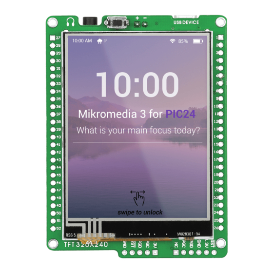
Page 22: Touch Screen
The development system features a 320x240 display resistive covered with a touch panel. Together they form a functional Figure 8-1: unit called a touch screen. It enables data to Touch Screen be entered and displayed at the same time. The TFT display is capable of showing data 262.000 diffe rent colors. - Page 23 BC846 VCC-SYS VCC-SYS VCC-3.3 BC846 BC846 PMD5 VCC-3.3 PMD6 PMD7 LCD-RS 10uF VCC-3.3 300K 47nF VCC-3.3 300K 47nF VCC-3.3 Figure 8-2: Touch Screen connection schematic Page 23...
-
Page 24: Audio Module
Figure 9-1: On-board VS1053 MP3 codec The mikromedia for PIC24 features MP3 codec audio controller VS1053. This Figure 9-2: Inserting 3.5mm module enables audio reproduction by using stereo headphones connected to the headphones jack system via a 3.5mm connector CN2. All functions of this module are controlled by the microcontroller over Serial Peripheral Interface (SPI). - Page 25 LEFT VCC-3.3 RIGHT GBUF PHONEJACK 10uF VCC-3.3 VCC-1.8 MICP GPIO4 47nF MICN MP3-RST# XRESET GPIO1 DGND0 GPIO0 CVDD0 XTEST VS1053 IOVDD0 CVDD3 R22 27 MISO2-MP3 MISO2-RG7 CVDD1 MOSI2-RG8 MP3-RST# SCK2-RG6 DREQ MISO2-RG7 SCK2-RG6 GPIO2 SCLK MOSI2-RG8 GPIO3 LEFT MP3-RST# GPIO6 VCC-3.3 MP3-DREQ GPIO7...
-
Page 26: Usb Connection
PIC24FJ256GB110 microcontroller has integrated USB OTG module, which enables you to implement USB communication functionality of your mikromedia board. Connection with target USB host is done over miniUSB connector which is positioned next to the battery connector. Figure 10-1: Connecting USB cable to programming connector Page 26... - Page 27 10uF USB-DET USB-ID USBDP USBDM USB MINI B VCC-USB SCK2-RG6 FERRITE MOSI2-RG8 10nF VCC-3.3 USBDP USBDM 10uF USB-DET REG1 VCC-SYS USB-ID VOUT LD29080DT33 10uF VCC-3.3 Figure 10-2: USB module connection schematic Page 27...
-
Page 28: Accelerometer
On board ADXL345 accelerometer is used to measure acceleration in three axis: x- y- and z-. The acceleromer’s function is defined by the user in the program loaded into the microcontroller. Communication between the accelerometer and the microcontroller is performed I 2 C over the interface. -
Page 29: Crystal Oscillator
Board is equipped with 8Mhz crystal oscillator circuit that provides external clock to the microcontroller OSC pins. This base frequency is suitable for further PLL clock multipliers and ideal for generation of necessary USB clock, which ensures proper operation of bootloader and your custom USB- based applications. -
Page 30: Pads
10uF MOSI1-RD0 SCK1-SD10 FLASH-CS# RF13 STAT SDA1-RA15 MISO1-RC4 RD12 SCK2-RG6 SCL1-RA14 RD13 MISO2-RG7 SCL1-RA14 MOSI2-RG8 SDA1-RA15 RD11 SCK1-RD10 MISO1-RC4 MOSI1-RD0 RB14 SDA2-RA3 RG13 SCL2-RA2 RX-RD3 RG14 TX-RD1 SCK2-RG6 USBDM SCL2-RA2 MISO2-RG7 SDA2-RA3 MOSI2-RG8 VCC-3.3 VCC-3.3 M1X26 M1X26 VCC-3.3 Pads HDR1 Pads HDR2 Figure 13-1: Pads connecting schematic Most microcontroller pins are available for further connectivity via two 1x26 rows of... -
Page 31: Pinout
5V power supply Reset pin Reference Ground Reference Ground PGED1/RP0/AN0/CN2 left ch. audio out PGEC1/RP1/AN1/CN3 right ch. RP13/C2INB/AN2/CN4 RP4/DPLN/CN54 VPIO/C2INA/AN3/CN5 RP30/CN70 PGED3/RP28/AN4/CN6 RP10/PMA9/CN17 PGEC3/RP18/AN5/CN7 RP17/PMA8/CN18/ RP9/AN9/CN27 RP15/CN74 C3INB/CN15 RF13 RP31/CN76 C3INA/CN16 TMS/CN33 RPI42/CN57 RD12 TCK/CN34 CN19 RD13 RPI33/CN66 RPI36/SCL1/CN43 RA14 RPI34/CN67 RPI35/SDA1/CN44 RA15... -
Page 32: Dimensions
80.90 mm (3.18”) 73.01 mm (2.87”) 69.85 mm (2.75”) 4.45 mm (0.17”) 2.54 mm (0.10”) 2.77 mm (0.11”) Page 32... - Page 33 Notes: Page 33...
- Page 34 Notes: Page 34...
- Page 35 No part of this manual, including product and software described herein, may be reproduced, stored in a retrieval system, translated or transmitted in any form or by any means, without the prior written permission of MikroElektronika. The manual PDF edition can be printed for private or local use, but not for distribution.
- Page 36 If you want to learn more about our products, please visit our website at www.mikroe.com If you are experiencing some problems with any of our products or just need additional information, please place your ticket at www.mikroe.com/en/support If you have any questions, comments or business proposals, do not hesitate to contact us at office@mikroe.com...
Need help?
Do you have a question about the mikromedia PIC24 and is the answer not in the manual?
Questions and answers