Table of Contents
Advertisement
BMW Parts and Accessories
Installation Instructions
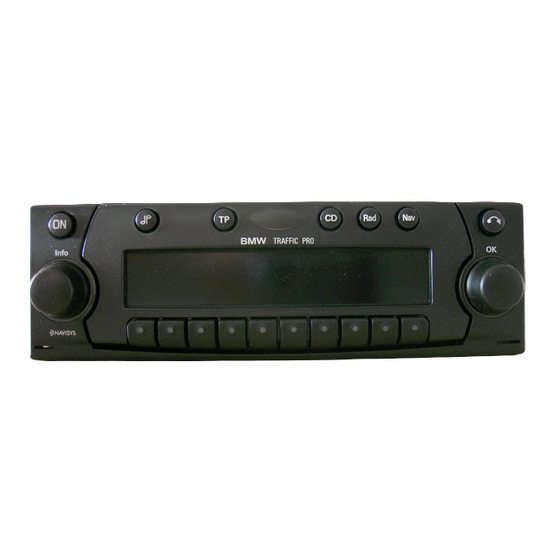
BMW Traffic Pro installation kit
BMW 5 Series Saloon (E 39) with a production date after 09/00
BMW 5 Series touring (E 39/2) with a production date after 09/00
These installation instructions are not valid for cars with SA358 (climate comfort windscreen).
These installation instructions are onlyvalid for :
•
cars without an on-board monitor, without SA663 (BMW Professional radio) with a
production date after 09/00
•
cars without an on-board monitor, with SA663 (BMW Professional radio) with a production
date after 02/01
Technical and electrical knowledge required
The installation time is approx. 1.5 hours but this may vary depending on the condition of the
car and the equipment in it.
Retrofit/Installation kit No. 65 90 0 027 973
Retrofit / Installation kit No. 65 90 0 027 973 (others see cover sheet)
Installation Instructions No. 01 29 0 140 447
65 90 0 139 839
Issue date: 06.2001
ON
ON
ON
TP
TP
TP
BMW
BMW
Info
Inf nfo
CD
CD
CD
Rad
Rad
ad
Nav
Nav
OK
OK
OK
039 0004 B
Advertisement
Table of Contents

Related Manuals for BMW E39


Summary of Contents for BMW E39
- Page 1 SA663 (BMW Professional radio) with a production date after 09/00 • cars without an on-board monitor, with SA663 (BMW Professional radio) with a production date after 02/01 Technical and electrical knowledge required The installation time is approx. 1.5 hours but this may vary depending on the condition of the car and the equipment in it.
-
Page 2: Table Of Contents
Contents Section Page Important information for the installation of the navigation radio ....Preparations ............Parts list . -
Page 3: Important Information For The Installation Of The Navigation Radio
Important information for the installation of the navigation radio Only for use in the BMW dealer organisation. The navigation radio may only be installed by a specialist workshop that has the required special tools and manuals. Ensure that the cables/lines are not kinked or damaged as you install them in the car. -
Page 4: Preparations
Preparations TIS instruction No. Conduct a brief test Disconnect the battery 12 00 ... Remove the instrument cluster 62 21 000 Remove the radio 65 11 030 Remove the glove compartment 51 16 360 Remove the front right door sill trim 51 47 000 Remove the A pillar trim at the bottom right Remove the centre air jet... -
Page 5: Parts List
Parts list Inf nfo Info Bedienungsanleitung 039 0005 B Legend Adapter cable Aerial adapter Navigation radio Radio retaining pin Double insulation-piercing connector (2x) Cable tie (8x) GPS aerial GPS aerial holder Hexagonal screws (2x) Rattle guard (2x) Radio installation trim 10 Installation clip (2x) 11 Shrink hose 12 Owner’s manual... -
Page 6: Adapter Cable Connection Diagram
Adapter cable connection diagram 039 0006 B Cable colour / Abbreviation / Item Description Signal Connection location in the car Cross-section Slot Adapter cable Black 16-pin plug casing To black 16-pin plug casing in the X18126 centre console Black 16-pin socket casing To the navigation radio in the centre console Red 20-pin socket casing... -
Page 7: Adapter Cable Connection Overview (Lhd Cars Only)
Adapter cable connection overview (LHD cars only) 039 0025 B Lay the adapter cable A, as shown in the figure, and secure it with cable ties . Branch A1 to the black 16-pin plug casing X18126 in the centre console Branch A2 to the navigation radio in the centre console Branch A3 to the navigation radio in the centre console Branch A4 to the standard wiring harness on the A pillar at the front right using a double... -
Page 8: Adapter Cable Connection Overview (Rhd Cars Only)
Adapter cable connection overview (RHD cars only) 039 0041 B Lay the adapter cable A, as shown in the figure, and secure it with cable ties . Branch A1 to the black 16-pin plug casing X18126 in the centre console Branch A2 to the navigation radio in the centre console Branch A3 to the navigation radio in the centre console Branch A4 to the standard wiring harness on the A pillar at the front right using a double... -
Page 9: Navigation Radio Connection Diagram
Navigation radio connection diagram 13 16 15 18 14 17 039 0021 B Legend Chamber A Chamber C2 Speed signal (TAA) 7-12 Specific connection for CD changer Signal from reversing light Telephone mute Chamber C3 Continuous positive (terminal 30) Low frequency telephone input Control output for automatic aerial/amplifier 14 Earth telephone input Light (terminal 58G) -
Page 10: To Install The Gps Aerial (Lhd Cars Only)
To install the GPS aerial (LHD cars only) Remove the plate (30) from the GPS aerial (5). 039 0008 B Place the GPS aerial (5) on the holder (6) (the aerial will be held in place by integrated magnets). 039 0042 B The figure shows the installation site of the GPS aerial under the instrument panel. -
Page 11: To Install The Gps Aerial (Rhd Cars Only)
To install the GPS aerial (RHD cars only) Remove the plate (30) from the GPS aerial (5). 039 0008 B Place the GPS aerial (5) on the holder (6) (the aerial will be held in place by integrated magnets). 039 0009 B The figure shows the installation site of the GPS aerial under the instrument panel. -
Page 12: To Install The Adapter Cable And Connect The Navigation Radio
10. To install the adapter cable and connect the navigation radio The figure shows the radio module holder (30). Remove the flap (31) on the radio module holder (30) to allow the radio trim (9) to be installed. Remove the pins (32) for this purpose. 039 0011 B Insert the radio trim (9). - Page 13 10. To install the adapter cable and connect the navigation radio Affix a rattle guard (8) to the second rattle guard (8) A1+30 and then affix them to the wiring harness so that the plug connector A1 + new generation (30) is wrapped in them.
- Page 14 10. To install the adapter cable and connect the navigation radio Carefully slide the connected navigation radio (1) into the radio shaft (30) and secure it with the existing slides. Refer to the information for securing the navigation radio in the operating instructions in the section headed Installation/Removal instructions.
-
Page 15: To Connect The Tacho A Signal
To connect the tacho A signal Cars with high instrument cluster (SA 555) only The figure shows installation location of the instrument cluster. Open and release the white 18-pin instrument cluster connection plug X10113. Connect branch A5, 1-pin socket contact, black/ white cable on the tacho A signal cable, to the free slot PIN3 on the connection plug X10113. -
Page 16: Coding
Reassemble the car by following the instructions for its dismantling in reverse order Print out error memory 14. Language selection and commissioning See enclosed BMW Traffic Pro operating instructions 15. Owner’s manual See enclosed BMW Traffic Pro operating instructions EN/16 Retrofit / Installation kit No. -
Page 17: Adapter Wiring Harness Circuit Diagram
16. Adapter wiring harness circuit diagram EN/17 Retrofit / Installation kit No. 65 90 0 027 973 (others see cover sheet) Installation Instructions No. 01 29 0 140 447 Issue date: 06.2001... - Page 18 Blade terminal contact (X10113 PIN 3) Blade terminal contact (X11175 PIN 14) The components marked with an asterisk (*) are only valid for this circuit diagram. All the other components and X designations correspond to BMW after-sales circuit diagrams Cable colours = red...
Need help?
Do you have a question about the E39 and is the answer not in the manual?
Questions and answers