
Subscribe to Our Youtube Channel
Related Manuals for SMA SUNNY BOY 3300TL HC


Summary of Contents for SMA SUNNY BOY 3300TL HC
- Page 1 PV Inverter SUNNY BOY 3300TL HC Installation Guide SB3300TLHC-IEN094121 | IME-SB33TLHC | Version 2.1...
-
Page 3: Table Of Contents
SMA Solar Technology AG Table of Contents Table of Contents Notes on this Manual......5 Validity . - Page 4 Table of Contents SMA Solar Technology AG Commissioning ........26 Display Message .
-
Page 5: Notes On This Manual
Notes on this Manual 1 Notes on this Manual This manual describes the mounting, installation, commissioning and servicing of the SMA inverters of the type Sunny Boy 3300TL HC (SB 3300TL HC). Store this manual where it will be accessible at all times. 1.1 Validity This manual is valid for the Sunny Boy 3300TL HC. -
Page 6: Symbols Used
Notes on this Manual SMA Solar Technology AG 1.4 Symbols Used The following types of safety instructions and general information appear in this document as described below: DANGER! DANGER indicates a hazardous situation which, if not avoided, will result in death or serious injury. -
Page 7: Safety
The free design program "Sunny Design" (www.SMA.de/en/SunnyDesign) will assist you. The manufacturer of the PV modules must have approved the modules for use with this Sunny Boy unit. You must also ensure that all measures recommended by the module manufacturer for long-term maintenance of the module properties are taken (see also Technical Information "Module Technology", in the download area of... -
Page 8: Safety Instructions
• Attach the Electronic Solar Switch again. Grounding the PV generator Comply with the local requirements for grounding the modules and the PV generator. SMA reccomends to electrically bond the module frames, the racks and all metal surfaces and ground these in order to have optimal protection of the system and personnel. -
Page 9: Overview
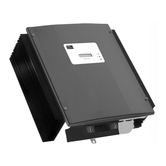
SMA Solar Technology AG Overview 3 Overview 3.1 Identifying the Sunny Boy You can identify the Sunny Boy using the type label. The type label can be found on the right side of the housing and contains information about the serial number, the device type as well as technical data. -
Page 10: Mounting
Mounting SMA Solar Technology AG 4 Mounting 4.1 Selecting the Mounting Location DANGER! Danger to life due to fire or explosion! Despite careful construction, a fire can occur with electrical devices. • Do not mount the Sunny Boy on flammable construction materials. -
Page 11: Safety Clearances
SMA Solar Technology AG Mounting • In a living area, do not mount the unit on plasterboard walls (or similar) in order to avoid audible vibrations. The Sunny Boy can make noises when in use which can be regarded as a nuisance when installed in a living area. -
Page 12: Mounting The Sunny Boy
Mounting SMA Solar Technology AG 4.2 Mounting the Sunny Boy To make the job easier, we recommend you use the supplied wall bracket to mount the Sunny Boy. For vertical installation on solid concrete or block walls, for example, you can fit the bracket using 8 mm x 50 mm hexagon bolts to DIN 571 standard, stainless steel type, and with wall plugs type SX10. - Page 13 SMA Solar Technology AG Mounting 1. Mount the wall bracket (1). In order to mark the positions for the drill holes, you can use the wall bracket as a drilling template. 2. Now hang the Sunny Boy onto the wall bracket (2) using its upper mounting plate so that it cannot be moved sideways.
-
Page 14: Electrical Connection
Electrical Connection SMA Solar Technology AG 5 Electrical Connection 5.1 Overview Connection Area NOTICE! Electrostatic discharges can damage the Sunny Boy! Internal components of the Sunny Boy can be irreparably damaged by electrostatic discharge. • Ground yourself before you touch a component. -
Page 15: View From Below
SMA Solar Technology AG Electrical Connection 5.1.1 View from Below Electronic Solar Switch (ESS) AC plug for the mains socket supply connection Plug and socket Cable openings for optional connector for connection communication via RS485 or of the solar modules radio (PG16) -
Page 16: View From Inside
Electrical Connection SMA Solar Technology AG 5.1.2 View from Inside The following diagram gives a schematic overview of the various components and connection points inside the Sunny Boy with the cover removed: Object Description Socket for communication (RS485, radio), section 5.5 ”The Communications Interface”... -
Page 17: Low Voltage Grid (Ac)
The connection is made with three wires (L, N, PE). Examples for the rating of a line circuit breaker can be found in the Technical Information "line circuit breaker" in the download area of www.SMA.de/en. The Sunny Boy is equipped with an integrated universal current sensitive leakage-current monitoring unit. -
Page 18: Connection Of The Ac Output
Electrical Connection SMA Solar Technology AG 5.2.1 Connection of the AC Output Connection requirements of the grid operator Always observe the connection requirements of your grid operator! To connect the AC cable, proceed as follows: 1. Check the grid voltage. Complying with DIN VDE 0126-1-1, the Sunny Boy will not be fully operational if the grid voltage is constantly higher than 253 V. -
Page 19: Pv Generator Requirements
The unit has four DC plug connectors (two for each string) for connecting the PV generators. The connecting cables from the PV generators must also be fitted with this type of plug connector. The SMA order codes for the various connectors are as follows [see also section 12 ”Accessories” (page 39)]: •... -
Page 20: Pv String (Dc) Connection
Electrical Connection SMA Solar Technology AG 5.3.1 PV string (DC) connection DANGER! Danger to life due to high voltages on the Sunny Boy! • Before connecting the PV generator, ensure that the line circuit breaker is switched off. Use of Adaptors Adaptors (branch connectors) are not to be visible or freely accessible in the immediate surrounding of the Sunny Boy, in order that the DC circuit is not disrupted as a result. - Page 21 SMA Solar Technology AG Electrical Connection NOTICE! Exceeding the maximum input voltage can destroy the Sunny Boy! If the voltage of the PV modules exceeds the maximum input voltage of the Sunny Boy, it can be destroyed by the overvoltage. All warranty claims become void.
-
Page 22: Setting The Display Language
Electrical Connection SMA Solar Technology AG NOTICE! Manipulating the connector in the handle can damage the Electronic Solar Switch! The connector within the handle must remain movable in order to ensure proper contact. Tightening the screw voids all warranty claims and creates a fire risk. -
Page 23: The Communications Interface
Electrical Connection 5.5 The Communications Interface The communication interface is used to communicate with SMA communication devices (e.g. Sunny Boy Control, Sunny WebBox) or a PC with appropriate software (e.g. Sunny Data Control). Depending on the selected communication interface, up to 2500 inverters can be interconnected. -
Page 24: Connection Rs485, Radio Piggy-Back
SMA Solar Technology AG 5.5.1 Connection RS485, Radio Piggy-Back This section describes the installation of the Piggy-Backs for the different Sunny Boy communication systems: RS485 interface and Radio Piggy-Back. You can take the relevant SMA order numbers from the section 12 ”Accessories” (page 39). NOTICE! -
Page 25: Jumper Functions
SMA Solar Technology AG Electrical Connection 10. Plug the communication interface to the left of the board (F). 11. Close the Sunny Boy as described in section 7.2 ”Closing the Sunny Boy” (page 30). Enclosure openings in the base of the Sunny Boy. -
Page 26: Commissioning
Commissioning SMA Solar Technology AG 6 Commissioning Check the following requirements before commissioning: • The cover is securely screwed on. • The AC (power) cable is connected correctly. • The DC cables (PV-Strings) are fully connected. • The unused DC plug connectors on the underside of the housing are sealed with protecting caps. -
Page 27: Display Message
SMA Solar Technology AG Commissioning 6.1 Display Message Feeding Operation After fault-free grid connection of the Sunny Boy, it takes approximately one minute until the following display messages are shown alternately. The display messages shown before only have the purpose of indicating the initialization of the Sunny Boy and the process of controlling whether the power supply requirements are fulfilled. -
Page 28: Blink Codes
If despite checking the string voltages the LED signal occurs again when the PV generator is connected to the Sunny Boy, disconnect the PV generator from the Sunny Boy again and contact SMA Solar Technology (see section 13 ”Contact” (page 40)). -
Page 29: Sunny Boy Opening And Closing
SMA Solar Technology AG Sunny Boy Opening and Closing 7 Sunny Boy Opening and Closing NOTICE! Electrostatic discharges can damage the Sunny Boy! Internal components of the Sunny Boy can be irreparably damaged by electrostatic discharge. • Ground yourself before you touch a component. -
Page 30: Closing The Sunny Boy
Sunny Boy Opening and Closing SMA Solar Technology AG 7.2 Closing the Sunny Boy 1. Reconnect the protective earth (PE) to the housing cover. 2. Now secure the lid to the Sunny Boy by tightening the four screws evenly. The screws must be tightened with approximately 4 Nm torque in order to guarantee the sealing of the housing. -
Page 31: Maintenance And Cleaning
(as illustrated below), proper functioning of the Electronic Solar Switch is no longer guaranteed. worn-out metal tongues 3. Replace the defective Electronic Solar Switch, before you re-commission the Sunny Boy. You can purchase replacements from SMA Solar Technology (see section 12 ”Accessories” (page 39)). Installation Guide SB3300TLHC-IEN094121... -
Page 32: Troubleshooting
The Sunny Boy is a complex high-technology device. As a result, the possibilities for fixing faults on site are limited to just a few items. Do not attempt to carry out repairs other than those described here. Use the SMA Solar Technology 24-hour replacement service and repair service instead. 9.1 The red LED is continuously lit If the red LED of the status display is continuously on during operation, there is either a ground fault in the PV generator or at least one of the varistors for the overvoltage protection is defective. -
Page 33: Checking The Function Of The Varistors
SMA Solar Technology AG Troubleshooting 3. Repeat step 2 for each string. 4. The table illustrated below shows the various results and corresponding measures. Result Measure You have found a ground fault. • The installer of the PV generator must remedy the ground fault in the affected string before you may reconnect the string to the Sunny Boy. - Page 34 4. Close the Sunny Boy as described in section 7.2 ”Closing the Sunny Boy” (page 30). If no ground fault and no defective varistor were found, there is probably a fault in the Sunny Boy. In this case, contact the SMA Serviceline to discuss what to do next. SB3300TLHC-IEN094121...
-
Page 35: Decommissioning
Dispose of the Sunny Boy at the end of its service life in accordance with the disposal regulations for electronic waste which apply at the installation site at that time. Alternatively, send it back to SMA Solar Technology with shipping paid by sender, and labeled "ZUR ENTSORGUNG" ("for disposal"). -
Page 36: Technical Data
Technical Data SMA Solar Technology AG 11 Technical Data PV generator connection data Setting Max. input voltage 750 V DC max Input voltage, MPP range 125 V ... 600 V Max. input current 11 A PV max Max. input power 3440 W Voltage ripple <... - Page 37 General Data EC Declaration of Conformity You will find the EC Declaration of Conformity in the accompanying document set or in the download area of www.SMA.de/en under Certificate. Protection category per DIN EN 60529 IP65 Dimensions (W x H x D) approx.
-
Page 38: Efficiency Curve
Technical Data SMA Solar Technology AG Communication Interfaces RS485 (galvanically isolated) optional Radio optional Electronic Solar Switch Electrical lifetime (in the event of a short circuit, min. 50 switching processes with a nominal current of 30 A) Maximum switching current... -
Page 39: Accessories
SMA Solar Technology AG Accessories 12 Accessories You will find the corresponding accessories and replacement parts for your product In the following overview. If needed, you can order these from SMA Solar Technology or your dealer. designation Brief description SMA order number Replacement varistors Set of thermally monitored varistors (2 pcs.) -
Page 40: Contact
Contact SMA Solar Technology AG 13 Contact If you have technical problems concerning our products, please contact our Serviceline. We require the following information in order to provide you with the necessary assistance: • Inverter type • Type and number of modules connected •... - Page 41 SMA Solar Technology AG Contact Installation Guide SB3300TLHC-IEN094121...
- Page 42 Contact SMA Solar Technology AG SB3300TLHC-IEN094121 Installation Guide...
-
Page 43: Exclusion Of Liability
The use of supplied software produced by SMA Solar Technology AG is subject to the following conditions: • SMA Solar Technology AG rejects any liability for direct or indirect damages arising from the use of software developed by SMA Solar Technology AG. This also applies to the provision or non-provision of support activities. - Page 44 SMA Solar Technology AG www.SMA.de...
Need help?
Do you have a question about the SUNNY BOY 3300TL HC and is the answer not in the manual?
Questions and answers