Table of Contents
Advertisement
Quick Links
Advertisement
Table of Contents

Related Manuals for VIA Technologies epia-m860


Summary of Contents for VIA Technologies epia-m860
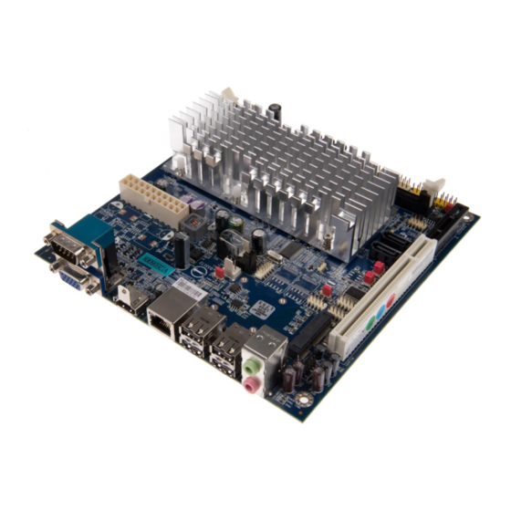
- Page 1 USER MANUAL EPIA-M860 Mini-ITX embedded board 1.14-06212013-165600...
-
Page 2: Regulatory Compliance
The information and product specifications within this document are subject to change at any time, without notice and without obligation to notify any person of such change. VIA Technologies, Inc. reserves the right the make changes to the products described in this manual at any time without prior notice. -
Page 3: Safety Precautions
Battery Recycling and Disposal Only use the appropriate battery specified for this product. Do not re-use, recharge, or reheat an old battery. Do not attempt to force open the battery. Do not discard used batteries with regular trash. Discard used batteries according to local regulations. Safety Precautions Always read the safety instructions carefully. - Page 4 M860- - - - 12 12 12 12E E E E (ATX version) (ATX version) (ATX version) (ATX version) 1 x EPIA-M860 embedded board 1 x I/O bracket 1 x SATA cable EPIA EPIA- - - - M860 M860- - - - 12...
-
Page 5: Table Of Contents
EPIA EPIA- - - - M860 M860 User Manual User Manual EPIA EPIA M860 M860 User Manual User Manual Table of Contents 1.1. Key Features and Benefits................1 1.1.1. VIA Nano™ 1.2GHz Processor............. 1 1.1.2. VIA VX900 Chipset................. 2 1.1.3. Flexible Power Options ................ - Page 6 EPIA EPIA- - - - M860 M860 User Manual User Manual EPIA EPIA M860 M860 User Manual User Manual 2.2.14. Digital I/O Pin Header................27 2.2.15. SPI Pin Header ..................28 3.1. AT/ATX Mode..................... 29 3.2. SATA DOM Power Select Jumper ............30 3.3.
- Page 7 EPIA EPIA- - - - M860 M860 User Manual User Manual EPIA EPIA M860 M860 User Manual User Manual 6.5.5. ACPI Configuration ................53 6.5.6. APM Configuration................54 6.5.7. Spread Spectrum Configuration ............58 6.5.8. USB Configuration................. 59 6.5.9. CRB Configuration................. 61 6.6.
- Page 8 ..........................83 83 A.1. EPIA-M860 ......................83 A.1.1. Playing DVDs (ATX)................... 83 A.1.2. Playing DVDs (DC-in) ................84 A.1.3. Playing MP3s (ATX)..................84 A.1.4. Playing MP3s (DC-in) ................. 84 A.1.5. Copying files on a network (ATX)............85 A.1.6.
- Page 9 EPIA EPIA- - - - M860 M860 User Manual User Manual EPIA EPIA M860 M860 User Manual User Manual List of Tables ® Table 1: HDMI port pinout ..................10 Table 2: VGA port pinout ..................... 11 Table 3: COM port pinout .................... 12 Table 4: USB port pinout....................
- Page 10 Figure 1: Layout diagram of the EPIA-M860 mainboard........... 6 Figure 2: Mounting holes and dimensions of the EPIA-M860 mainboard.... 7 Figure 3: External I/O port dimensions of the EPIA-M860 mainboard ....7 Figure 4: Height distribution of the EPIA-M860 mainboard ........8 Figure 5: External I/O ports.....................
- Page 11 EPIA EPIA- - - - M860 M860 User Manual User Manual EPIA EPIA M860 M860 User Manual User Manual Figure 32: DDR3 memory slot ..................35 Figure 33: Installing memory 1..................36 Figure 34: Installing memory 2..................36 Figure 35: Removing memory 1 ................... 37 Figure 36: Removing memory 2 ...................
- Page 12 EPIA EPIA- - - - M860 M860 User Manual User Manual EPIA EPIA M860 M860 User Manual User Manual Figure 65: Illustration of Exit Options screen ............78 Figure 66: Installing the PCIE-03 riser card..............89 Figure 67: Installing the EXT-PCI-01 riser card............90...
-
Page 13: Key Features And Benefits
TwinTurbo™ technology. The VIA EPIA-M860 includes one 1066 MHz DDR3 DIMM slot that supports up to 4 GB. The VIA EPIA-M860 provides support for high fidelity audio with its included VIA VT1708S High Definition Audio codec. In addition it supports two SATA 3Gb/s storage devices. -
Page 14: Via Vx900 Chipset
1.1.3. Flexible Power Options The VIA EPIA-M860 comes with two power input options: ATX and DC-in. The ATX version supports standard 20-pin ATX power supply connectors. The DC- in version requires a 12V/5A max input. The AC/DC adapter can be purchased as an option with the DC-in version. -
Page 15: Product Specifications
EPIA EPIA- - - - M860 M860 User Manual User Manual EPIA EPIA M860 M860 User Manual User Manual 1.2. Product Specifications Processor Processor Processor Processor VIA Nano 1.2 GHz 6.8W TDP fanless 7 bit VID Chipset Chipset Chipset Chipset... - Page 16 EPIA EPIA- - - - M860 M860 User Manual User Manual EPIA EPIA M860 M860 User Manual User Manual 1 x SMBUS pin header 1 x Mini PCIe x1 slot (with 1 USB port) 1 x PCI slot ...
- Page 17 EPIA EPIA- - - - M860 M860 User Manual User Manual EPIA EPIA M860 M860 User Manual User Manual Operating Conditions Operating Conditions Operating Conditions Operating Conditions Operating Temperature Operating Temp erature Operating Temp Operating Temp erature erature 0°C ~ 60°C Operating Humidity Operating Humidity Operating Humidity...
-
Page 18: Layout Diagram
EPIA EPIA- - - - M860 M860 User Manual User Manual EPIA EPIA M860 M860 User Manual User Manual 1.3. Layout Diagram Figure Figure 1 1 1 1 : Layout diagram of : Layout diagram of the the EPIA EPIA- - - - M860 M860 mainboard mainboard Figure... -
Page 19: Product Dimensions
EPIA EPIA- - - - M860 M860 User Manual User Manual EPIA EPIA M860 M860 User Manual User Manual 1.4. Product Dimensions Figure Figure Figure Figure 2 2 2 2 : Mounting holes and dimensions of : Mounting holes and dimensions of : Mounting holes and dimensions of : Mounting holes and dimensions of the EPIA the EPIA... -
Page 20: Height Distribution
EPIA EPIA- - - - M860 M860 User Manual User Manual EPIA EPIA M860 M860 User Manual User Manual 1.5. Height Distribution Figure Figure 4 4 4 4 : Height distribution of : Height distribution of the the EPIA EPIA- - - - M860 M860 mainboard mainboard Figure... -
Page 21: External I/O Ports
2. 2. 2. 2. I/O Interface I/O Interface I/O Interface I/O Interface The VIA EPIA-M860 has a wide selection of interfaces integrated into the board. It includes a selection of frequently used ports as part of the external I/O coastline. 2.1. External I/O Ports... -
Page 22: Hdmi Port
EPIA EPIA- - - - M860 M860 User Manual User Manual EPIA EPIA M860 M860 User Manual User Manual ® 2.1.1. HDMI Port ® ® The integrated 19-pin HDMI port uses an HDMI Type A receptacle ® connector. The pinout of the HDMI port is as shown below. -
Page 23: Vga Port
EPIA EPIA- - - - M860 M860 User Manual User Manual EPIA EPIA M860 M860 User Manual User Manual 2.1.2. VGA Port The integrated 15-pin VGA port uses a female DE-15 connector. The pinout of the VGA port is as shown below. Figure Figure Figure... -
Page 24: Com Port
EPIA EPIA- - - - M860 M860 User Manual User Manual EPIA EPIA M860 M860 User Manual User Manual 2.1.3. COM Port The integrated 9-pin COM port uses a male DE-9 connector. The pinout of the COM port is as shown below. Figure Figure Figure... -
Page 25: Gigabit Ethernet Port
EPIA EPIA- - - - M860 M860 User Manual User Manual EPIA EPIA M860 M860 User Manual User Manual 2.1.5. Gigabit Ethernet Port The integrated 8-pin Gigabit Ethernet port is using an 8 Position 8 Contact (8P8C) receptacle connector (commonly referred to as RJ45). The pinout of the Gigabit Ethernet port is as shown below. -
Page 26: Dc-In Jack
EPIA EPIA- - - - M860 M860 User Manual User Manual EPIA EPIA M860 M860 User Manual User Manual 2.1.7. DC-in Jack For the DC version of the mainboard, there is a coaxial power connector adjacent to the COM/VGA connector stack. The specifications of the DC coaxial power connector are shown below Physical Specifications Physical Specifications... -
Page 27: Onboard Connectors
EPIA EPIA- - - - M860 M860 User Manual User Manual EPIA EPIA M860 M860 User Manual User Manual 2.2. Onboard Connectors 2.2.1. ATX Power Connector For the ATX version of the mainboard, there is a 20-pin ATX power connector onboard. -
Page 28: Dc-In Power Connector
EPIA EPIA- - - - M860 M860 User Manual User Manual EPIA EPIA M860 M860 User Manual User Manual 2.2.2. DC-in Power Connector For the DC version of the mainboard, there is a DC-in power connecter in addition to the DC-in coaxial power connector. This enables two methods for delivering +12V to the mainboard. -
Page 29: Sata Power Connector
EPIA EPIA- - - - M860 M860 User Manual User Manual EPIA EPIA M860 M860 User Manual User Manual 2.2.3. SATA Power Connector For the DC version of the mainboard, there are two built-in SATA power connectors. These connectors are required to power SATA hard drives. The SATA power connectors are labeled as “S_PWR1”... -
Page 30: Cmos Battery Slot
EPIA EPIA- - - - M860 M860 User Manual User Manual EPIA EPIA M860 M860 User Manual User Manual 2.2.4. CMOS Battery Slot Depending on the manufacturing option, the mainboard will either be equipped with a CMOS battery slot or a 2-prong cable CMOS battery connector. -
Page 31: Front Panel Pin Header
EPIA EPIA- - - - M860 M860 User Manual User Manual EPIA EPIA M860 M860 User Manual User Manual 2.2.5. Front Panel Pin Header The front panel pin header consists of 15 pins in a 16-pin block. Pin 15 is keyed. -
Page 32: Smbus Pin Header
EPIA EPIA- - - - M860 M860 User Manual User Manual EPIA EPIA M860 M860 User Manual User Manual 2.2.6. SMBus Pin Header The SMBus pin header consists of three pins. It is labeled as “SMBUS1”. The pinout of the SMBus pin header is shown below. Signal Signal Signal... -
Page 33: Fan Connectors
EPIA EPIA- - - - M860 M860 User Manual User Manual EPIA EPIA M860 M860 User Manual User Manual 2.2.8. Fan Connectors There are two fan connectors on board: one for the CPU and one for the chassis. The fan connectors are the standard 3-prong fan connectors. The pinout of the fan connectors is shown below. -
Page 34: Sata Connectors
EPIA EPIA- - - - M860 M860 User Manual User Manual EPIA EPIA M860 M860 User Manual User Manual 2.2.9. SATA Connectors The two SATA connectors on board can support up to 3 Gb/s transfer speeds. The SATA connectors are labeled as “SATA1” and “SATA2”. The pinout of the SATA connectors are as shown below. -
Page 35: Usb Pin Headers
EPIA EPIA- - - - M860 M860 User Manual User Manual EPIA EPIA M860 M860 User Manual User Manual 2.2.10. USB Pin Headers The mainboard has two USB pin header blocks that support up to three USB 2.0 ports. The pin header blocks are labeled as “USB_3” and “USB_4”. USB_4 only supports one USB 2.0 port. -
Page 36: Com Pin Headers
EPIA EPIA- - - - M860 M860 User Manual User Manual EPIA EPIA M860 M860 User Manual User Manual 2.2.11. COM Pin Headers There are a total of three COM pin headers on the mainboard . Each COM pin header supports the RS-232 standard. The pin headers are labeled as “COM2”, “COM3”, and “COM4”. -
Page 37: Ps/2 Keyboard And Mouse Pin Header
EPIA EPIA- - - - M860 M860 User Manual User Manual EPIA EPIA M860 M860 User Manual User Manual 2.2.12. PS/2 Keyboard and Mouse Pin Header The mainboard has a pin header for a PS/2 keyboard and mouse. The pin header is labeled as “JKB/MS1”. -
Page 38: Front Audio Pin Header
EPIA EPIA- - - - M860 M860 User Manual User Manual EPIA EPIA M860 M860 User Manual User Manual 2.2.13. Front Audio Pin Header In addition to the TRS audio jacks on the external I/O coastline, the mainboard has a pin header for Line-out and MIC-in. The pin header is labeled as “F_AUDIO1”. -
Page 39: Digital I/O Pin Header
EPIA EPIA- - - - M860 M860 User Manual User Manual EPIA EPIA M860 M860 User Manual User Manual 2.2.14. Digital I/O Pin Header The onboard Digital I/O pin header supports up to four GPO and four GPI signals. The pin header is labeled as “DIO1”. The pinout of the pin header is shown below. -
Page 40: Spi Pin Header
EPIA EPIA- - - - M860 M860 User Manual User Manual EPIA EPIA M860 M860 User Manual User Manual 2.2.15. SPI Pin Header The mainboard has one 8-pin SPI pin header. The pin header is labeled as “SPI1”. The pinout of the pin header is shown below. Figure Figure 27 27: SPI pin header... -
Page 41: At/Atx Mode
Jumpers and Switches 3.1. AT/ATX Mode For the ATX version of the EPIA-M860, there is a jumper that can enable to mainboard to switch between two power modes: AT and ATX. The jumper is labeled as “J10”. The jumper settings are shown below. -
Page 42: Sata Dom Power Select Jumper
EPIA EPIA- - - - M860 M860 User Manual User Manual EPIA EPIA M860 M860 User Manual User Manual 3.2. SATA DOM Power Select Jumper The SATA connectors (see page 22) can be used to support Disk-on-Module flash drives. When the jumpers are set, +5V will be delivered to the 7 pin of the SATA connectors. -
Page 43: Clear Cmos Jumper
EPIA EPIA- - - - M860 M860 User Manual User Manual EPIA EPIA M860 M860 User Manual User Manual 3.3. Clear CMOS Jumper The onboard CMOS RAM stores system configuration data and has an onboard battery power supply. To reset the CMOS settings, set the jumper on pins 2 and 3 while the system is off. -
Page 44: Com Voltage Select Jumpers
EPIA EPIA- - - - M860 M860 User Manual User Manual EPIA EPIA M860 M860 User Manual User Manual 3.4. COM Voltage Select Jumpers Each of the additional COM ports (available through the onboard COM pin headers, see page 24) can support both +5V and +12V. COM2 has its own pin header block. -
Page 45: Com3 And Com4 Voltage Select Jumper
EPIA EPIA- - - - M860 M860 User Manual User Manual EPIA EPIA M860 M860 User Manual User Manual 3.4.2. COM3 and COM4 Voltage Select Jumper The voltage for COM3 and COM4 is controlled by the jumper labeled as “J7”. Refer to Figure 31 for the location of the jumper. - Page 46 EPIA EPIA- - - - M860 M860 User Manual User Manual EPIA EPIA M860 M860 User Manual User Manual...
-
Page 47: Ddr3 Memory Slot
EPIA EPIA- - - - M860 M860 User Manual User Manual EPIA EPIA M860 M860 User Manual User Manual 4. 4. 4. 4. Expansion Slots Expansion Slots Expansion Slots Expansion Slots 4.1. DDR3 Memory Slot The DDR3 memory slot can accommodate up to 4 GB of 1066 MHz memory. The location of the DDR3 memory slot is as shown below. -
Page 48: Installing A Memory Module
EPIA EPIA- - - - M860 M860 User Manual User Manual EPIA EPIA M860 M860 User Manual User Manual 4.1.1. Installing a Memory Module Step 1 Step 1 Step 1 Step 1 Disengage the locking clasps at both ends of the memory slot. Figure Figure Figure... -
Page 49: Removing A Memory Module
EPIA EPIA- - - - M860 M860 User Manual User Manual EPIA EPIA M860 M860 User Manual User Manual 4.1.2. Removing a Memory Module Step 1 Step 1 Step 1 Step 1 Disengage the locking clasps on both sides of the memory slot. Figure Figure Figure... -
Page 50: Mini Pcie Slot
EPIA EPIA- - - - M860 M860 User Manual User Manual EPIA EPIA M860 M860 User Manual User Manual 4.2. Mini PCIe Slot The Mini PCIe slot is compatible with all PCIe 2.0 Mini Cards: full-length and half-length. The location of the Mini PCIe slot is shown below. Figure Figure 37 37: Mini PCIe slot... -
Page 51: Pci Express Slot
EPIA EPIA- - - - M860 M860 User Manual User Manual EPIA EPIA M860 M860 User Manual User Manual 4.3. PCI Express Slot The onboard PCI Express slot is located adjacent to the PCI slot. The PCI Express slot provides support for 1-lane cards. Due to the orientation of the slot, a riser card module must be used. -
Page 52: Pci Slot
EPIA EPIA- - - - M860 M860 User Manual User Manual EPIA EPIA M860 M860 User Manual User Manual 4.4. PCI Slot The onboard PCI slot supports 5V 32-bit PCI cards. It is not compatible with PCI cards requiring 3.3V signaling. The PCI slot is located adjacent to the PCI Express slot. -
Page 53: Installing Into A Chassis
Hardware Installation 5.1. Installing into a Chassis The EPIA-M860 can be fitted into any chassis that has the mounting holes compatible with the standard Mini-ITX mounting hole locations. Additionally, the chassis must meet the minimum height requirements for specified areas of the mainboard. -
Page 54: Suggested Minimum Chassis Height
EPIA EPIA- - - - M860 M860 User Manual User Manual EPIA EPIA M860 M860 User Manual User Manual Each side of the mainboard should have a buffer zone from the internal wall of the chassis. The side of the mainboard that accommodates the I/O coastline should have a buffer of 1.00 mm. -
Page 55: Suggested Keepout Areas
EPIA EPIA- - - - M860 M860 User Manual User Manual EPIA EPIA M860 M860 User Manual User Manual 5.1.3. Suggested keepout areas The figure below shows the areas of the mainboard that is highly suggested to leave unobstructed. Figure Figure Figure Figure 42... -
Page 57: Entering The Bios Setup Utility
EPIA EPIA- - - - M860 M860 User Manual User Manual EPIA EPIA M860 M860 User Manual User Manual 6. 6. 6. 6. BIOS Setup BIOS Setup Utility Utility BIOS Setup BIOS Setup Utility Utility 6.1. Entering the BIOS Setup Utility Power on the computer and press Delete Delete during the beginning of the boot Delete... -
Page 58: Getting Help
EPIA EPIA- - - - M860 M860 User Manual User Manual EPIA EPIA M860 M860 User Manual User Manual 6.3. Getting Help The BIOS Setup Utility provides a “General Help” screen. This screen can be accessed at any time by pressing F1 F1 F1 F1. The help screen displays the keys for using and navigating the BIOS Setup Utility. -
Page 59: System Time
EPIA EPIA- - - - M860 M860 User Manual User Manual EPIA EPIA M860 M860 User Manual User Manual This section shows the amount of available memory that has been detected. 6.4.4. System Time This section shows the current system time. Press Tab Tab to traverse right and Shift+Tab Shift+Tab to traverse left through the hour, minute, and second segments. -
Page 60: Advanced Settings
EPIA EPIA- - - - M860 M860 User Manual User Manual EPIA EPIA M860 M860 User Manual User Manual 6.5. Advanced Settings The Advanced Settings screen shows a list of categories that can provide access to a sub-screen. Sub-screen links can be identified by the preceding right-facing arrowhead. -
Page 61: Cpu Configuration
EPIA EPIA- - - - M860 M860 User Manual User Manual EPIA EPIA M860 M860 User Manual User Manual 6.5.1. CPU Configuration The CPU Configuration screen shows detailed information about the built-in processor. In addition to the processor information, the thermal controls can be set. -
Page 62: Ide Configuration
EPIA EPIA- - - - M860 M860 User Manual User Manual EPIA EPIA M860 M860 User Manual User Manual 6.5.2. IDE Configuration The IDE Configuration screen shows links to the primary master and slave SATA hard drive information screens. Figure Figure 46 46: Illustration of IDE Configuration screen : Illustration of IDE Configuration screen... -
Page 63: Superio Configuration
EPIA EPIA- - - - M860 M860 User Manual User Manual EPIA EPIA M860 M860 User Manual User Manual 6.5.3. SuperIO Configuration The SuperIO Configuration screen shows the specific addresses and IRQs of the onboard serial ports. Figure Figure Figure Figure 48 48 48 48: Illustration of SuperIO Configuration screen... -
Page 64: Hardware Health Configuration
EPIA EPIA- - - - M860 M860 User Manual User Manual EPIA EPIA M860 M860 User Manual User Manual 6.5.4. Hardware Health Configuration The Hardware Health Configuration screen has no editable fields. The system temperature is taken from an optional sensor that is connected to the J5 pin header. -
Page 65: Acpi Configuration
EPIA EPIA- - - - M860 M860 User Manual User Manual EPIA EPIA M860 M860 User Manual User Manual 6.5.5. ACPI Configuration ACPI grants the operating system direct control over system power management. The ACPI Configuration screen can be used to set a number of power management related functions. -
Page 66: Apm Configuration
EPIA EPIA- - - - M860 M860 User Manual User Manual EPIA EPIA M860 M860 User Manual User Manual 6.5.6. APM Configuration APM enables the operating system to co-work with the BIOS to control the system power management. The APM Configuration screen can be used to set a number of power management functions. - Page 67 EPIA EPIA- - - - M860 M860 User Manual User Manual EPIA EPIA M860 M860 User Manual User Manual 6.5.6.2. 6.5.6.2. Restore on AC/Power Loss Restore on AC/Power Loss 6.5.6.2. 6.5.6.2. Restore on AC/Power Loss Restore on AC/Power Loss Restore on AC/Power Loss defines how the system will respond after AC power has been interrupted while the system is on.
- Page 68 EPIA EPIA- - - - M860 M860 User Manual User Manual EPIA EPIA M860 M860 User Manual User Manual 6.5.6.4. 6.5.6.4. 6.5.6.4. 6.5.6.4. Wake Wake Wake Wake- - - - Up Key Up Key Up Key Up Key The Wake-Up Key feature can only be set when Resume on PS/2 KBC Resume on PS/2 KBC Resume on PS/2 KBC Resume on PS/2 KBC is set to...
-
Page 69: Resume On Rtc Alarm
Resume on RTC Alarm will be disabled. Resume on RTC Alarm Note: Note: Note: Note: 1. FliteDeck is a system management suite developed by VIA Technologies, Incorporated. 6.5.6.8. 6.5.6.8. Resume on RTC Alarm Resume on RTC Alarm 6.5.6.8. 6.5.6.8. Resume on RTC Alarm... -
Page 70: Spread Spectrum Configuration
EPIA EPIA- - - - M860 M860 User Manual User Manual EPIA EPIA M860 M860 User Manual User Manual 6.5.7. Spread Spectrum Configuration The Spread Spectrum Configuration screen enables access to the Spread Spectrum Setting feature. Figure Figure 52 52: Illustration of Spread Spectrum Configuration screen : Illustration of Spread Spectrum Configuration screen Figure Figure... -
Page 71: Usb Configuration
EPIA EPIA- - - - M860 M860 User Manual User Manual EPIA EPIA M860 M860 User Manual User Manual 6.5.8. USB Configuration The USB Configuration screen shows the number of connected USB devices. Additionally, support for various USB features can be enabled or disabled. Figure Figure 53 53: Illustration of USB Configuration screen... - Page 72 EPIA EPIA- - - - M860 M860 User Manual User Manual EPIA EPIA M860 M860 User Manual User Manual Enabled Enabled Enabled Enabled The Enabled option keeps the Legacy USB Support feature on at all times. Disabled Disabled Disabled Disabled The Disabled option keeps the Legacy USB Support feature off at all times.
-
Page 73: Crb Configuration
EPIA EPIA- - - - M860 M860 User Manual User Manual EPIA EPIA M860 M860 User Manual User Manual 6.5.9. CRB Configuration The CRB Configuration screen shows the available BIOS-controlled LAN features. Figur Figure e e e 54 54: Illustration of CRB Configuration screen : Illustration of CRB Configuration screen Figur Figur... -
Page 74: Advanced Pci/Pnp Settings
EPIA EPIA- - - - M860 M860 User Manual User Manual EPIA EPIA M860 M860 User Manual User Manual 6.6. Advanced PCI/PnP Settings The Advanced PCI/PnP Settings screen shows the features that relate to PCI bus and Plug and Play devices. Only change these settings if a PCI or Plug and Play device requires it. -
Page 75: Pci Latency Timer
EPIA EPIA- - - - M860 M860 User Manual User Manual EPIA EPIA M860 M860 User Manual User Manual The No option gives the BIOS control over handling resource conflicts caused by Plug and Play devices. 6.6.3. PCI Latency Timer The PCI Latency Timer feature enables the user to specify the number of PCI bus cycles a connected PCI device can control before handing control of the PCI bus to the next PCI device waiting to use it. -
Page 76: Pci Ide Busmaster
EPIA EPIA- - - - M860 M860 User Manual User Manual EPIA EPIA M860 M860 User Manual User Manual 6.6.6. PCI IDE BusMaster The PCI IDE BusMaster feature enables IDE controllers on the PCI bus to directly communicate with IDE hard disks connected to PCI IDE cards. This feature has two options: enabled and disabled. -
Page 77: Hotplug Reserve Memory Size
EPIA EPIA- - - - M860 M860 User Manual User Manual EPIA EPIA M860 M860 User Manual User Manual 6.6.11. HotPlug Reserve Memory Size The HotPlug Reserve Memory Size feature enables the user to set aside a specified portion of the memory block for hot-swappable or CardBus devices. The available options range from 8MB to 512MB. -
Page 78: Boot Settings
EPIA EPIA- - - - M860 M860 User Manual User Manual EPIA EPIA M860 M860 User Manual User Manual 6.7. Boot Settings The Boot Settings screen has a single link that goes to the Boot Settings Boot Settings Boot Settings Boot Settings Configuration Configuration screen. - Page 79 EPIA EPIA- - - - M860 M860 User Manual User Manual EPIA EPIA M860 M860 User Manual User Manual 6.7.1.1. 6.7.1.1. 6.7.1.1. 6.7.1.1. Quick Boot Quick Boot Quick Boot Quick Boot The Quick Boot feature enables the BIOS to skip certain tests in order to speed up the boot sequence.
- Page 80 EPIA EPIA- - - - M860 M860 User Manual User Manual EPIA EPIA M860 M860 User Manual User Manual Disabled Disabled Disabled Disabled The Disabled option forces the BIOS to make IRQ12 available to any device. 6.7.1.6. 6.7.1.6. Wait for ‘F1’ if Error Wait for ‘F1’...
-
Page 81: Security Settings
EPIA EPIA- - - - M860 M860 User Manual User Manual EPIA EPIA M860 M860 User Manual User Manual 6.8. Security Settings The Security Settings screen provides a way to restrict access to the BIOS or even the entire system. Figure Figure 58 58: Illustration of Security Settings screen... -
Page 82: Password Check
EPIA EPIA- - - - M860 M860 User Manual User Manual EPIA EPIA M860 M860 User Manual User Manual 6.8.2. Password Check This feature is compulsory when the Change Supervisor Password Change Supervisor Password Change Supervisor Password Change Supervisor Password option is set. The user will have up to three chances to enter the correct password before the BIOS forces the system to stop booting. -
Page 83: Advanced Chipset Settings
EPIA EPIA- - - - M860 M860 User Manual User Manual EPIA EPIA M860 M860 User Manual User Manual 6.9. Advanced Chipset Settings The Advanced Chipset Settings screen has two links for accessing North and South bridge functions. Though the VX900 is a single chip solution, the North and South bridge categories are still for grouping features. - Page 84 EPIA EPIA- - - - M860 M860 User Manual User Manual EPIA EPIA M860 M860 User Manual User Manual 6.9.1.1. 6.9.1.1. 6.9.1.1. 6.9.1.1. DRAM Clock/Timing Configuration DRAM Clock/Timing Configuration DRAM Clock/Timing Configuration DRAM Clock/Timing Configuration The DRAM Clock/Timing Configuration screen has one feature for controlling the system DRAM.
- Page 85 EPIA EPIA- - - - M860 M860 User Manual User Manual EPIA EPIA M860 M860 User Manual User Manual 6.9.1.2. 6.9.1.2. 6.9.1.2. 6.9.1.2. AGP & P2P Bridge Configuration AGP & P2P Bridge Configuration AGP & P2P Bridge Configuration AGP & P2P Bridge Configuration The AGP &...
- Page 86 EPIA EPIA- - - - M860 M860 User Manual User Manual EPIA EPIA M860 M860 User Manual User Manual 6.9.1.3. 6.9.1.3. OnChip VGA Configuration OnChip VGA Configuration 6.9.1.3. 6.9.1.3. OnChip VGA Configuration OnChip VGA Configuration The OnChip VGA Configuration screen has features for controlling the integrated graphics controller in the VX900 chipset.
-
Page 87: South Bridge Via Vx900 Configuration
EPIA EPIA- - - - M860 M860 User Manual User Manual EPIA EPIA M860 M860 User Manual User Manual 6.9.2. South Bridge VIA VX900 Configuration The South Bridge VIA VX900 Configuration screen has seven features. Figure Figure 64 64: Illustration of South Bridge VIA VX900 Configuration sc : Illustration of South Bridge VIA VX900 Configuration screen reen Figure... - Page 88 EPIA EPIA- - - - M860 M860 User Manual User Manual EPIA EPIA M860 M860 User Manual User Manual 6.9.2.4. 6.9.2.4. 6.9.2.4. 6.9.2.4. HPET Support HPET Support HPET Support HPET Support The HPET Support feature enables the BIOS to determine if the high precision event timer in the chipset is on or off.
- Page 89 EPIA EPIA- - - - M860 M860 User Manual User Manual EPIA EPIA M860 M860 User Manual User Manual 6.9.2.11. 6.9.2.11. 6.9.2.11. 6.9.2.11. EuP/ErP Lot6 Support EuP/ErP Lot6 Support EuP/ErP Lot6 Support EuP/ErP Lot6 Support The EuP/ErP Lot6 Support feature enables the BIOS to reduce the power draw to less than 1W when the system is in standby mode.
-
Page 90: Exit Options
EPIA EPIA- - - - M860 M860 User Manual User Manual EPIA EPIA M860 M860 User Manual User Manual 6.10. Exit Options Figure Figure Figure Figure 65 65 65 65: Illustration of Exit Options screen : Illustration of Exit Options screen : Illustration of Exit Options screen : Illustration of Exit Options screen 6.10.1. - Page 91 EPIA EPIA- - - - M860 M860 User Manual User Manual EPIA EPIA M860 M860 User Manual User Manual environment for a basic system. The “F9” hotkey can also be used to trigger this command.
-
Page 93: Microsoft Driver Support
Driver Installation Driver Installation 7.1. Microsoft Driver Support The VIA EPIA-M860 mainboard is compatible with Microsoft operating systems. The latest Windows drivers can be downloaded from the VIA Embedded website at www.viaembedded.com. For embedded operating systems, the related drivers can be found in the VIA Embedded website at www.viaembedded.com. -
Page 95: Appendix A. Power Consumption Report
Power Consumption Report Power Consumption Report Power Consumption Report Power Consumption Report Power consumption tests were performed on the VIA EPIA-M860. The following tables represent the breakdown of the voltage, amp and wattage values while running common system applications. A.1. EPIA-M860... -
Page 96: Playing Dvds (Dc-In)
EPIA EPIA- - - - M860 M860 User Manual User Manual EPIA EPIA M860 M860 User Manual User Manual A.1.2. Playing DVDs (DC-in) This benchmark was performed using PowerDVD 8.0 using the HDMI interface. Test results exclude SATA power. Power Plane Power Plane Volts Volts... -
Page 97: Copying Files On A Network (Atx)
EPIA EPIA- - - - M860 M860 User Manual User Manual EPIA EPIA M860 M860 User Manual User Manual A.1.5. Copying files on a network (ATX) Power Plane Power Plane Power Plane Power Plane Volts Volts Volts Volts Amperes Amperes Amperes Amperes Watts... -
Page 98: Idle (Dc-In)
EPIA EPIA- - - - M860 M860 User Manual User Manual EPIA EPIA M860 M860 User Manual User Manual A.1.8. Idle (DC-in) Test results exclude SATA power. Power Plane Power Plane Power Plane Power Plane Volts Volts Volts Volts Amperes Amperes Amperes Amperes... -
Page 99: S3 (Atx)
EPIA EPIA- - - - M860 M860 User Manual User Manual EPIA EPIA M860 M860 User Manual User Manual A.1.11. S3 (ATX) Power Plane Power Plane Power Plane Power Plane Volts Volts Volts Volts Amperes Amperes Amperes Amperes Watts Watts Watts Watts +3.3V... -
Page 101: Appendix B. Riser Card Modules Appendix B. Riser Card Modules
Riser Card Modules Modules There are two riser card modules that are compatible with the EPIA-M860: the PCIE-03 and the EXT-PCI-01. B.1. PCIE-03 The PCIE-03 riser card has both a PCI slot and a PCIe x1 slot. This card can only be used if the mainboard has a PCI slot properly aligned with a PCIe x1 slot. -
Page 102: Ext-Pci-01
EPIA EPIA- - - - M860 M860 User Manual User Manual EPIA EPIA M860 M860 User Manual User Manual B.2. EXT-PCI-01 The EXT-PCI-01 card is compatible with both 5V and 3.3V PCI slots. However, the PCI slots on the riser card are only compatible with 5V PCI cards. The EXT-PCI-01 riser card must be correctly inserted into the mainboard’s PCI slot, otherwise it may be damaged when the system powers on. - Page 103 Taiwan Headquarters Europe 1F, 531 Zhong-Zheng Road 940 Mission Court In den Dauen 6 Xindian District, New Taipei City 231, Fremont, CA 94539 53117 Bonn Taiwan Germany TEL: 886.2.2218.5452 TEL: 1.510.683.3300 TEL: 49.228.688565.0 FAX: 886.2.2218.5453 FAX: 1.510.687.4654 FAX: 49.228.688565.19 Email: embedded@via.com.tw Email: embedded@viatech.com Email: embedded@via-tech.de China...
Need help?
Do you have a question about the epia-m860 and is the answer not in the manual?
Questions and answers