
Subscribe to Our Youtube Channel
Related Manuals for Crow PowerWave-16


Summary of Contents for Crow PowerWave-16
-
Page 1: Programming Guide
ELECTRONIC ENGINEERING LTD PowerWave – 16 16 Zone Control Panel Communicator Installation and Programming Guide P/N 7111240 Rev. B N.A Version 6.20 07/2002... -
Page 3: Table Of Contents
CONTENTS INTRODUCTION ....................4 PACKAGE CONTENTS ..................4 PW16 CABINET DETAILS ................5 INPUTS ......................6 OUTPUTS ......................7 PANEL COMMUNICATION PORTS ..............7 PCB WIRING DIAGRAM ...................8 PW16 KEYPADS ....................9 KEYPAD INSTALLATION ................10 KEYPAD FUNCTIONS ..................12 KEYPAD TAMPER ..................12 MEMORY DISPLAY CHART ................13 INSTALLING RX-40 RADIO RECEIVER............15 INSTALLING SPEECH/DTMF UNIT.............. -
Page 4: Introduction
INTRODUCTION This Crow PowerWave Version V6 alarm control panel has been designed to provide the most requested features for both the installer & the end-user. These features include ease of installation, ease of programming and user friendly operation all in a package which is reliable, functional and attractive. - Page 5 PLASTIC HOUSING DETAILS MOUNTING KEYHOLES WIRELESS RX-16 PowerWave Controler PCB CABLE ENTRY MAINS BLOCK Install Battery Here POWE R CABLE TAMPER ENTRY ASSEMBLY Page 5...
-
Page 6: Inputs
INPUTS The Elite V6 has 10 separate programmable monitored analogue inputs, Programmable, multi-state detection inputs Programmable tamper input Programmable keyswitch input Each input must be terminated with a short or the appropriate combination of end-of-line resistors, depending upon the programmed configuration. ZONE INPUTS - Each of the 8 zone inputs can be independently assigned one of the following configuration options;... -
Page 7: Outputs
INPUTS Cont. KEYSWITCH - This input can be used to control the panel via a keyswitch, digital keypad or similar. This is a multi- state input which can be end-of-line configured in the same way as the 8 zone inputs. These multiple end-of-line configurations will produce either set/unset or stay mode on/off on an individual partition basis. -
Page 8: Pcb Wiring Instructions
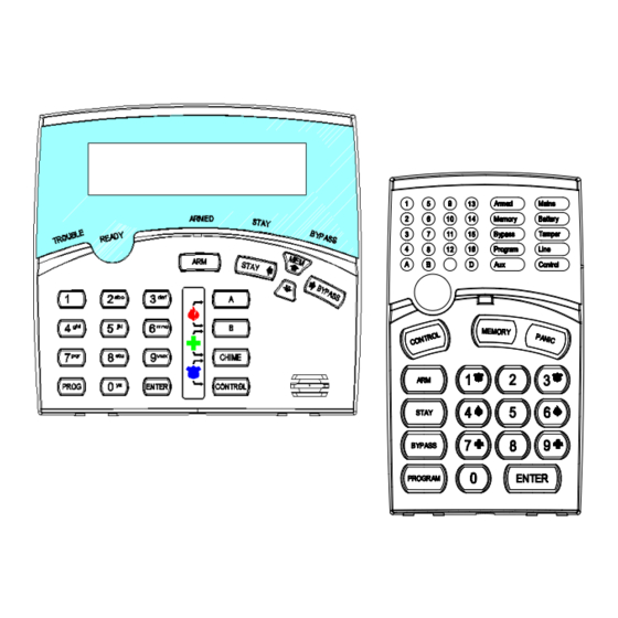
PCB WIRING INSTRUCTIONS From Line Line Connection To Telephone Line Line From Line Transformer Phone Listen-in to Output 1 Black - To Batt (-) Listen Data Keypad & Communication Clock Serial Port Port Red - To Batt (+) Key- Siren Driver Links Batt To Outputs 1 &... - Page 9 PW-16 KEYPAD OPTIONS LCD-KEYPAD Multiple language versions LED indicators … READY , ARMED, TROUBLE…. 3 KeyPad activated alarms …. FIER,MEDICAL, PANIC Audible feedback of correct key entries, pre-alert , system trouble Backlit keypad and display with boost control keypad tone control Large 32-character LCD display - system menus and prompts - trouble indications...
-
Page 10: Keypad Installation
KEYPAD INSTALLATION INSTALLATION Separate the two keypad halves by carefully inserting a small screwdriver into the release slots on the bottom edge of the keypad front half and applying a gentle pressure. This will release the bottom edge of the housing enough for you to unclip the top. - Page 11 C B A C B A KEYPAD KEYPAD C B A C B A KEYPAD KEYPAD C B A C B A KEYPAD KEYPAD C B A C B A KEYPAD KEYPAD When the Elite keypad is displaying numeric values in program mode it uses the zone LEDS 1-8 to indicate a value of 1-8 and to maintain consistency with the 8 zone LED keypad, the panel uses the “A”...
-
Page 12: Keypad Functions
KEYPAD FUNCTIONS The PW LED Keypad consists of; an 18 button, backlit silicone rubber keypad, 30 LED indicators and an internal piezo buzzer housed in a modern white plastic housing. The plastic housing has a hinged front lid to cover and protect the rubber buttons when not in use. - Page 13 Cabinet or Satellite Siren TAMPER Flashing WRONG CODE ALARM Code Tamper at TAMPER On Steady Keypad # LED’s 1-8 On Steady CROW KEYPAD TAMPER SWITCH Keypad Tamper Alarm at TAMPER On Steady Keypad # LED’s 1-8 On Steady ACTIVATED LOW BATTERY Controller Battery...
- Page 14 VIEW MEMORY MODE HISTORICAL EVENT DISPLAY CHART-Continued EVENT DEVICE INDICATOR STATUS Radio Zone BATTERY Flashing LOW BATTERY-ZONE Zone 1-16 LED's 1-16 On Steady Radio Key BATTERY Flashing LOW BATTERY-PENDANT User 1-20 LED's On Steady 1-16,17,18,19,20 Zone 1-16 LED’s 1-16 On Steady ZONE INACTIVITY TIMEOUT TAMPER Flashing...
- Page 15 INSTALLATION OF RX-40 RECEIVER The PW16 is fully high level compatible with the RX-40 radio receiver. The addition of this receiver will add wireless capability to your system in the form of wireless PIR detectors, Wireless Radio key transmitters and wireless reed switch transmitters.
-
Page 16: Programming
PROGRAMMING YOUR PowerWave ACCESS TO INSTALLER PROGRAMMING ON POWER UP When power is applied to the controller for the first time, with the panel tamper input open and none of the Areas either fully Armed or in Stay mode, the panel will inhibit tamper alarms and ready the panel to enter PROGRAM Mode( unless the Installer Lock-out option P210E7E has previously been enabled). -
Page 17: Programming User Codes
TO EXIT PROGRAM MODES To exit program modes when you have finished programming: Press <PROGRAM> - <ENTER> Program light goes out The panel is now back in normal Run Mode, any program changes you have made will have replaced previous values and be in effect. - Page 18 To replace a code simply enter the new code in the same address as the old code. This will overwrite the previous code but maintain the user permissions as mapped to that user number. To clear or delete a code in LED Keypad simply press the BYPASS button at the address where the old code is stored.
-
Page 19: Installer Code
USER CODE TIME CONTROL P151E-P200E Users codes may have Time Zones assigned to control their operation. These Time Zones determine when a particular user code will work. Addresses P151E - P200E are used to map the user code to the required Time Zones. - Page 20 Option 1 Invert Output - This option is used to invert the normal state of the output. The PW16 uses open collector type transistor switches and the default state of all outputs is off or high. When in alarm the transistor switch is turned on and the output is switched low.
- Page 21 Option 6 Radio Key Panic Alarm to Output - This option is used to map the operation of the Radio Key Panic Alarm to an output i.e. when the Radio Panic is generated any output with this option enabled will turn Option 7 24 Hour Zone Alarm to Output - This option is used to map 24 Hour Zone Alarms to an output i.e.
- Page 22 P231E Where TZ represents a Time-Zone # from 1-8 which defines the turn on and turn off times required for output #1 Out 1 TZ A - - - - - - - - P232E - P238E As per above but for outputs 2-8 OUTPUT INHIBIT TIME ZONES P241E - P248E These addresses are used to map inhibit time-zones to each of the outputs as required.
- Page 23 Keypads with buzzer mapped to keypad tampers (Default 1-8) If the LED is On, a keypad tamper alarm (four incorrect attempts to enter in a code) or a Crow keypad tamper switch alarm will cause the buzzer at the keypad to sound.
- Page 24 P273E 1-8E Keypads with buzzer mapped to Pendant “Panic” Alarm (Default 1-8) If the LED is On, a radio Pendant Panic alarm will cause the buzzer at the keypad to sound. P274E 1-8E Keypads with buzzer mapped to keypad “Panic” or “(1 & 3)” Alarm (Default 1-8) If the LED is On, a Keypad Panic alarm will cause the buzzer at the keypad to sound.
- Page 25 as Day Zones to output #1. Zones are defined as Day Zones at P453E/P454E and P473E/P474E. Day zones are those which operate only during periods when the Area is disarmed and are normally used as door bells and shop minders etc. Option 8 Spare Note: P282E through P288E are as above but apply to outputs 2-8 for Area A...
-
Page 26: Partition 'A' Options
Note: P492E through P498E are as above but apply to outputs 2-8 for Area C PARTITION KEYPAD OPTIONS Arm Key Disarms PARTITION A - P299E & P300E 1 2 3 4 5 6 7 8 PARTITION B - P399E & P400E PARTITION C - P499E &... - Page 27 when the time zone programmed at address P290E starts. Option 3 Disable stay mode exit delay - If this option is on the exit delay for partition "A" becomes “0” when arming stay mode (the delay will still apply to full arm unless option 4 is also on). Option 4 Disable set mode exit delay - If this option is on the exit delay for partition "A"...
- Page 28 remaining exit delay time and make all Stay zones instant, even if they have an entry delay time programmed. Option 4 Code required to arm area - If this option is off the partition can be shortcut armed. Shortcut arming is when the area can be set by pressing the "ARM"...
- Page 29 assign the high value end-of-line (8k2) to Area "A" (refer to the zone drawing on page 6 Type 3 or 4). Also option 2 at address P311E selects whether a tamper is available when the 2nd key-switch is used. Option 3 Key-switch is used for arm or Stay - If this option is on, operating the Key-switch will arm Area "A".
- Page 30 restores as they occur. If the option is on, the dialler will send all zone restores only when the panel is disarmed. Option 7 Spare Option 8 Spare P389E 1-8E Area "B" Reporting Options - (see above for details) Default 1,2 P489E 1-8E Area "C"...
- Page 31 OPTIONS “B” KEY-SWITCH and TAMPER OPTIONS - P311E P311E 1E Cabinet tamper is loop or end-of-line 2E Key-switch input is loop or end-of-line 3E Low Key-switch is momentary or latching 4E High Key-switch is momentary or latching 5E Spare 6E Spare 7E Spare 8E Spare Option 1...
- Page 32 Only the first 8 zones may be defined as vibration sensor zones with a vibration sensitivity level as required. If a value other than zero is assigned at addresses P411E to P418E the zone which has been assigned that value automatically becomes a vibration zone.
- Page 33 open circuit on the input in this configuration will be seen as both the low and high zones in alarm. Finally, if this option is on and zone doubling is on for the same input the 2k2 resistor must be fitted in conjunction with the 4k7 and 8k2 resistors. In this mode, a short or open circuit on the input will be seen as a zone tamper alarm.
- Page 34 P449E 1-8E Two Trigger Zones - Where options 1-8 represent zones 1-8. A zone defined as two trigger at this address will only cause an activation if one of the following conditions are met; The zone is triggered twice within the two trigger time period as defined by Address P534E, P535E or P536E Any two zones defined as two trigger activate once each within the two trigger time period as defined by Address P534E, P535E or P536E...
- Page 35 HIGH ZONE ASSIGNMENTS ZONES 9-16 P461E - P480E Combinations of options in addresses P461E to P480E may be used to give the most suitable zone behaviour. P461E 1-8E Zone is in Area "A" - Where options 1-8 represent zones 9-16 respectively. This option assigns a zone to Area "A"...
- Page 36 P469E 1-8E Two Trigger Zones - Where options 1-8 represent zones 9-16 respectively. A zone defined as two trigger at this address will only cause an activation if one of the following conditions are met; The zone is triggered twice within the two trigger time period as defined by Address P534E, P535E or P536E Any two zones defined as two trigger activate once each within the two trigger time period as defined by Address P534E, P535E or P536E...
- Page 37 zone is unsealed (Not Ready) at the time of arming, by default the panel will Arm and the zone will either automatically be bypassed or cause an alarm at the end of the exit delay. If the option is turned on at this address then an unsealed condition will inhibit the panel from arming until the zone is sealed.
- Page 38 P556E 0-999E Output #6 reset time - Default 0 (latching) P557E 0-999E Output #7 reset time - Default 0 (latching) P558E 0-999E Output #8 reset time - Default 0 (latching) P559E 0-999E Mains Fail Dialler Report Delay - Default 600 seconds P560E 0-999E Zone Alarm Report Delay to Dialler - Default 0 seconds...
-
Page 39: Radio Zone Options
This block of addresses is used to specify a specific type of radio detector. Special functions such as detector tamper alarms, low battery indication and supervised signals can be selected based on the list below. 1 = Crow AE Series Battery low 2 = Crow AE Radio Reed Switch... -
Page 40: Radio Key Programming
ENROLLING RADIO KEYS - P640E 1-20E In the PW16 V6 we refer to wireless pendant transmitters as "Radio Keys". Because the PW16 recognises each button as a separate function or user we refer to each button or user separately in that if you are loading a three button radio key, you would actually be enrolling 3 separate radio users. - Page 41 P641E Radio user #1 Type - Default 0 0 = non-specific P642E Radio user #2 Type - Default 0 1 = Crow P643E Radio user #3 Type - Default 0 21 = Ness Radio user #4 Type - Default 0...
-
Page 42: Daylight Saving
This block of addresses is used to map radio users to outputs in conjunction with P681E - P700E. All output modifiers such as reset timers and lock out functions are maintained and will determine the behaviour of the assigned output. P701E 1-8E Radio user #1 to output 1-8 - Where options 1-8 represent outputs 1-8... -
Page 43: Dynamic Diagnostic Data
of the week P792E TZ1 Start Time P804E TZ5 Start Time P793E TZ1 Finish Time P805E TZ5 Finish Time P794E TZ2 Day of the week P806E TZ6 Day of the week P795E TZ2 Start Time P807E TZ6 Start Time P796E TZ2 Finish Time P808E TZ6 Finish Time P797E... -
Page 44: Event Buffer Printing
P833E Display software version - This address will cause t h e Clear all outputs panel software version to be flashed back at the keypad. P849E Active Time-Zones - If Time Zones are being used, entering in this address while in Installation Program M o d e the panel will display any of the 8 time zones currently active. -
Page 45: Reset Defaults
one where the data files were created and the panel receiving the files) must be the same otherwise the panel will not work correctly. DE-MAPPING OUTPUTS P846E 1-8E DE-mapping Outputs 1-8 - This option is used to remove ALL default options assigned to any output. -
Page 46: Command Control Programming
buzzer will beep at one second intervals to show that walk-test mode is active. When in walk test mode the zone LED’s will latch on at the keypad display when the zone has been activated. The Installer or User can then walk past all of the detectors and return to the keypad to verify that they are functioning correctly at the panel. - Page 47 next message. ON MESSAGE FOR ARM/DISARM STATUS MESSAGES If the ON message number is left blank i.e. “0”, the panel will assume that there is no voice message for this Command Control function and revert to the DTMF board tones e.g. One long tone for ON and three short beeps for OFF.
-
Page 48: Command Control Operation
Message #4 “ Area A alarm is Armed” Message #5 “ Area A alarm is Disarmed” Message #6 “ Area B alarm is Armed” Message #7 “ Area B alarm is Disarmed” Message #8 “ External lights are On” (external lights are connected to Output 5) Message #9 “... -
Page 49: Local Command Control Of Outputs
At any stage, if you enter in an incorrect code you can press the “#” button on the remote telephone to clear all code entries and then start again. To end a Command Control session simply hang up the phone. The panel is monitoring the line at all times and 15 seconds after the last key press it will automatically hang up the line. -
Page 50: Phone Number
Option 7 Auto-Detect Modem Format - The panel can connect using Bell103 or V21 formats when performing upload/download connections. If this option is On the panel generates the V21 tones first and if no connection is established it then generates the Bell103 tones. If this option is turned off then the format is fixed by the selection made at option 8. -
Page 51: Reporting Scenarios
Step 4 - If not kissed-off return to Ph # 2 (the 7 causes a return to the start). When kissed-off or the maximum re-tries reached, move forward to the next step. If no further steps, stop. The first step must be completed i.e. kissed-off or the maximum re-tries reached, before the panel can move past the first “7”, then it can step forward and execute additional instructions up to the next 7. - Page 52 Option 1 Monitor Call Progress - Monitor call progress means that the dialler monitors the status of the dialling tone to determine whether the call is valid or not. If the call is not valid, i.e. Engaged, the panel will know and hang up the call and try again.
- Page 53 P588E 1-4E Zone 8 Bypass mapped to Scenario 1-4 - Default 1 P589E 1-4E Zone 9 Bypass mapped to Scenario 1-4 - Default 1 P590E 1-4E Zone 10 Bypass mapped to Scenario 1-4 - Default 1 Zone 1 bypass Sc P591E 1-4E Zone 11 Bypass mapped to Scenario 1-4 - Default 1...
- Page 54 P434E Radio panic mapped to scenario 1-4 default 1 P435E Test calls mapped to scenario 1-4 default 1 P436E Duress alarm mapped to scenario 1-4 default 1 P437E Supervised radio timeout mapped to scenario 1-4 default 1 P438E Zone inactivity timeout mapped to scenario 1-4 default 1 MULTIPLE ZONE REPORTING P446E &...
- Page 55 MANUAL ALARM CONTACT ID REPORTING CODES P737E-P739E P737E XXXE “Panic” or “1&3” Keypad Alarm Default = 120 P738E XXXE “Fire” (4&6) Keypad Alarm Default = 110 P739E XXXE “Medical” (7&9) Keypad Alarm Default = 100 ZONE TAMPER ALARM CONTACT ID REPORTING CODES P741E-P756E P741E XXXE...
-
Page 56: Phone Options
AREA ARM/DISARM REPORTING OPTIONS P289E 1-8E Area “A” Reporting Options - Default 1,2 P389E 1-8E Area "B" Reporting Options - Default 1,2 P489E 1-8E Area "C" Reporting Options - Default 1,2 1 = Send Arm/Disarm 2 = Send Stay Mode Arm/Disarm A Phone Options 3 = Send Disarm only after activations 4 = Send Stay Disarm only after activations... -
Page 57: Mains Fail Reporting Delay
ENABLING VARIOUS DIALLER REPORTING OPTIONS B P315E 1-8E Various Reporting Options B (Default = 1,2,3) On = Send, Off = Don’t Send 1 = Report Panic Alarms via Dialler 2 = Report Fire Alarms via Dialler 3 = Report Medical Alarms via Dialler 4 = Report 24 Hour alarms for Voice/Domestic/Pager Mode KEYPAD LISTEN-IN OPTIONS P312E Keypad Listen-in Options (Default = 1,7) -
Page 58: Upload/Download Options
This delay pauses the reporting of zone alarms for all reporting formats. This delay can be used to prevent false alarms from reporting if the alarm is cancelled before this delay expires. UPLOAD/DOWNLOAD SECURITY OPTIONS P828E XXXXXXXX. Up to 8 digit security code for upload/download. P835E Answer incoming call - provided a user with option 5 set... - Page 59 Audible Panic Perimeter Zone 24 Hour Zone Entry Exit Zone Powerwave 16 PROGRAM SUMMARY GUIDE The following program summary is an abbreviated version of all the Elite program addresses. This is intended as a quick guide to finding a program address. The program addresses are in numerical order with page references beside them so you can get more detailed information if required.
- Page 60 — — P97E Standard Access Permissions for user #47 - Default 1-8 Page 18 P98E Standard Access Permissions for user #48 - Default 1-8 Page 18 P99E Standard Access Permissions for user #49 - Default 1-8 Page 18 P100E Standard Access Permissions for user #50 - Default 1-8 Page 18 Programming Extended User Code Permissions P101E...
- Page 61 Programming Output Options P201E Output #1 Primary options - Default none 1 = Invert Page 19 P202E Output #2 Primary options - Default none 2 = Flashing Page 19 P203E Output #3 Primary options - Default none 3 = Single pulse Page 19 P204E Output #4 Primary options - Default none...
- Page 62 P259E Keypads with buttons 1 & 3 Panic Alarm enabled - Default None Page 23 P260E Keypads with buttons 4 & 6 Fire Alarm enabled - Default None Page 23 P261E Keypads with buttons 7 & 9 Medical Alarm enabled - Default None Page 23 P262E Keypads with buzzer mapped for alarm tone for armed zone alarms - Default 1-8...
- Page 63 2 = “Arm” required before code 3 = “Stay” required before code 4 = Code required to arm 5 = Code required for control 6 = Control toggles 7 = Momentary control 8 = Control/Chime disables day zones Partition “A” Misc Options P302E Misc partition options 2 - Default 3,4,6 1 = Key-switch enabled...
-
Page 64: Programming Telephone Numbers
**Output #1 Listen-in Options** P313E Output # 1 Listen-in Options P313E Options (Default = Off) Page 57 1 = Enabled During Dialling in Disarm State only 2 = Enabled During Dialling in Armed State only 3 = Enabled During Dialling in Monitor Mode State only 4 = Enabled Throughout the call in Disarm State only 5 = Enabled Throughout the call in Armed State only 6 = Enabled Throughout the call in Monitor Mode State only... - Page 65 P342E Reporting Opts. Ph # 6 (Default= None) 5 = 4+2 10pps (Handshake 1400/ Tone 1800) 6 = 4+2 10pps (Handshake 1400/ Tone 1900) 7 = 4+2 10pps (Handshake 2300/ Tone 1800) 8 = 4+2 10pps (Handshake 2300/ Tone 1900) 9 = 4+2 20pps (Handshake 1400/ Tone 1800) 10= 4+2 20pps (Handshake 1400/ Tone 1900) 11= 4+2 20pps (Handshake 2300/ Tone 1800)
- Page 66 P375E Command code to turn “MICROPHONE” On Page 45 ** Contact ID Account Codes ** P376E Account number for Area "A" - default 0000 Page 54 P377E Account number for Area "B" Page 54 P378E Account number for Area "C" Page 54 Partition “B”...
- Page 67 Control/Chime disables day zones P402E Misc partitions options 2 - Default 3,4,6 1 = Key-switch enabled Page 28 2 = Use 2nd Key-switch 3 = Key-switch ARM's/STAY 4 = Pendant chirps when armed 5 = Pendant chirps when in Stay Mode 6 = 2 sec pulse at set 7 = 2 sec pulse at unset 8 = Access control even when armed...
- Page 68 P434E Radio panic mapped to scenario 1-4 default 1 Page 54 P435E Test calls mapped to scenario 1-4 default 1 Page 54 P436E Duress Alarm mapped to scenario 1-4 default 1 Page 54 P437E Supervised Radio Timeout mapped to scenario 1-4 default 1 Page 54 P438E...
- Page 69 Partition “C” Primary Output Options P481E-P488E OPTIONS P481E Area “C” primary options for output #1- Default 1 1 = Standard zone activation's Page 24 P482E Area “C” primary options for output #2 - Default 1 & 3 2 = Stay Mode activation's Page 24 P483E Area "C"...
- Page 70 4 = Disable Set Mode Exit Delay 5 = Disable Stay Mode Entry Delay 6 = Disable Set Mode Entry Delay 7 = Use special Stay Mode entry timer 8 = Report Stay Mode alarms & Bypasses via dialler System Delays & Timers P511E Zone 1 entry delay - Default 20 sec Delay timer values...
- Page 71 P561E Output #1 delay on timer - Default 0 Delay time values Page 37 P562E Output #2 delay on timer - Default 0 0 = no delay Page 37 P563E Output #3 delay on timer - Default 0 1 - 999 = 1 to 999 seconds Page 37 P564E Output #4 delay on timer - Default 0...
- Page 72 P624E Options for Zone # 4 (Default= 0) 3 = Crow Merlin PIR (Non-supervised) Page 38 P625E Options for Zone # 5 (Default= 0) 4 = Crow Merlin PIR (supervised signal active) Page 38 5 = Crow Merlin/checksum (supervise active) Page 38...
- Page 73 P666E Radio user #6 options - Default 1,4,5 6 = User can Arm Stay Mode Page 39 P667E Radio user #7 options - Default 1,4,5 7 = User can Disarm Stay Mode Page 39 P668E Radio user #8 options - Default 1,4,5 8 = User disabled if in alarm Page 39 P669E...
- Page 74 ** Contact ID Zone Alarm Code Assignments ** P721E Zone 1 activation - default = 130 Page 54 P722E Zone 2 activation - default = 130 Page 54 P723E Zone 3 activation - default = 130 Page 54 P724E Zone 4 activation - default = 130 Page 54 P725E Zone 5 activation - default = 130...
- Page 75 P768E Voice message number mapped to zone 8 activation - default 1 Page 55 P769E Voice message number mapped to zone 9 activation - default 1 Page 55 P770E Voice message number mapped to zone 10 activation - default 1 Page 55 P771E Voice message number mapped to zone 11 activation - default 1...
- Page 76 ** Upload/Download Security Code ** P828E XXXXXXXX. Up to 8 digit security code Page 58 Dynamic Data P830E Misc system flags 1 = Spare 5=Spare Page 42 2 = Spare 6=Spare 3 = Spare 7=Spare 4 = Spare 8=Daylight saving active P831E Display keyboard address Page 42...
- Page 77 P865E PA Board Output #5 Off Message - Default 0 P866E PA Board Output #6 Off Message - Default 0 P867E PA Board Output #7 Off Message - Default 0 P868E PA Board Output #8 Off Message - Default 0 PA Board Entry Delay Message P871E PA Board Area “A”...
- Page 78 P913E Keypad Fire Alarm PA Board Message default 0 P914E Keypad Medical Alarm PA Board Message default 0 **System Tamper 4+2 Reporting Code** P921E 4+2 Alarm Code for System Tamper (Default=86) Page 58 **System Tamper Restore 4+2 Reporting Code** P922E 4+2 Alarm Code for System Tamper Restore (Default=87) Page 58 **Armed by “Arm”...
- Page 79 **Zone Alarm Restore 4+2 Reporting Code** P961E 4+2 Alarm Restore Code for Zone 1 (Default=11) Page 58 P962E 4+2 Alarm Restore Code for Zone 2 (Default=12) Page 58 P963E 4+2 Alarm Restore Code for Zone 3 (Default=13) Page 58 P964E 4+2 Alarm Restore Code for Zone 4 (Default=14) Page 58 P965E 4+2 Alarm Restore Code for Zone 5 (Default=15) Page 58...
- Page 80 P1028E 4+2 Arm Code for User 8 (Default=48) Page 58 P1029E 4+2 Arm Code for User 9 (Default=49) Page 58 P1030E 4+2 Arm Code for User 10 (Default=50) Page 58 P1031E 4+2 Arm Code for User 11 (Default=41) Page 58 P1032E 4+2 Arm Code for User 12 (Default=42) Page 58 P1033E 4+2 Arm Code for User 13 (Default=43)
- Page 81 P1089E 4+2 Disarm Code for User 19 (Default=59) Page 58 P1090E 4+2 Disarm Code for User 20 (Default=60) Page 58 P1091E 4+2 Disarm Code for User 21 (Default=51) Page 58 P1092E 4+2 Disarm Code for User 22 (Default=52) Page 58 P1093E 4+2 Disarm Code for User 23 (Default=53) Page 58 P1094E 4+2 Disarm Code for User 24 (Default=54)
- Page 82 P1148E 4+2 Disarm Code for Radio User 8 (Default=78) Page 58 P1149E 4+2 Disarm Code for Radio User 9 (Default=79) Page 58 P1150E 4+2 Disarm Code for Radio User 10 (Default=80) Page 58 P1151E 4+2 Disarm Code for Radio User 11 (Default=71) Page 58 P1152E 4+2 Disarm Code for Radio User 12 (Default=72) Page 58...
- Page 83 COMMUNICATOR INTRODUCTION The communicator facility of this version 6 Elite controller has been designed to provide optimum flexibility in the way in which alarm events are reported. This flexibility includes options for reporting to a central monitoring station using Contact ID format, a domestic reporting option using alternating siren tones, a format for reporting alarms to an alpha numeric pager and a powerful speech dialler.
-
Page 84: Contact Id Code Summary
CONTACT ID CODE SUMMARY In addition to the programmable Contact ID Event Code assignments defined at P601E - P636E there are a num- ber of fixed event codes. The programmable and fixed event codes are all listed in the table below. Associated with the fixed and programmable event codes, there are a number of extension codes, that are also listed below. - Page 85 PowerWave 16 Version 6 Control Communicator Installation Guide Page 85...
Need help?
Do you have a question about the PowerWave-16 and is the answer not in the manual?
Questions and answers