Crow Runner Series User Manual
Wireless and wired control panel
Hide thumbs
Also See for Runner Series:
- Installation and configuration manual (192 pages) ,
- User manual (29 pages) ,
- Quick programming manual (2 pages)
Table of Contents
Advertisement
Advertisement
Table of Contents

Related Manuals for Crow Runner Series


Summary of Contents for Crow Runner Series
- Page 1 ELECTRONIC ENGINEERING LTD Runner Series 8 & 16 Zone IRELESS AND IRED ONTROL ANEL User’s Guide OVERS LCD K EYPAD REEN LUE WITH EXTUAL UTTONS & LCD K EYPAD LUE WITH YMBOL UTTONS & LED K & S EYPAD EXTUAL...
-
Page 2: Crow Limited Warranty
Subject to the provisions of this Warranty Certificate, during the Warranty Period, Crow undertakes, at its sole discretion and subject to Crow's procedures, as such procedures are from time to time, to repair or replace, free of charge for materials and/or labor, products proved to be defective in materials or workmanship under normal use and service. -
Page 3: Table Of Contents
Contents ........................2 IMITED ARRANTY INTRODUCTION ...........................1 ......................1 LARM ONTROL YSTEM ....................1 YPICAL LARM YSTEM ONFIGURATION KEYPAD LED TYPE DESCRIPTION ......................2 LED K ) ....................2 UNCTION EXTUAL EYPAD LED K ) ....................2 ... - Page 4 .....................12 OW TO NSWER AN OMING CID O ) ..............12 OW TO ENERATE A ANUAL ONITORED ....................13 SING THE EMOTE OMMAND ONTROL ......................14 SING OCAL OMMAND ONTROL KEYPAD LCD TYPE DESCRIPTION......................15 LCD K ) ....................15 UNCTION EXTUAL EYPAD...
- Page 5 ....................27 SING THE EMOTE OMMAND ONTROL ......................28 SING OCAL OMMAND ONTROL ....................29 DJUSTING ACKLIGHTING AND UZZER LCD K ......................30 EYPAD IN OCAL Accessing Local Edit Mode .........................30 Local Edit Mode Direct Program Addresses ..................30 LCD KEYPAD LOCAL EDIT MODE MENU PROGRAMMING ..............31 ...
-
Page 6: Introduction
We are really pleased that you chose to protect your premises and possibly even your lives with our RUNNER SERIES from Crow Electronic Engineering Ltd. The RUNNER SERIES is a highly advanced, multifunction alarm control system, designed to flawlessly manage your security system at home or at business, protects you against burglary and supports the operation of multiple electronic devices. -
Page 7: Keypad Led Type Description
KEYPAD LED Type Description The LED Keypad shows all the information required to operate the system. The User communicates with the alarm system via the keypad. The Keypad displays continuous information about the status of the alarm system, and enables the User to operate the system in different modes, change settings and program Users' access codes. -
Page 8: Audible Signals
Audible Signals When the keypad is used to activate or deactivate the different functions, it emits different audible beeps. Their meaning is described in the table below. Table 1 List of Audible Signals Sound Sequence Description Short beep Once only A key in the keypad has been pressed. - Page 9 Function Keys Description Notes un-bypass zones. Initiate Panic Activates panic alert PANIC Initiate Panic Activates emergency Only if enabled by alert installer. Initiate Activates emergency Only if enabled by Medical alert installer. Initiate Fire Activates emergency Only if enabled by ...
-
Page 10: Operating The Led Keypad
Operating the LED Keypad How to Arm the System before Exit (LED Keypad) Preparing the System for Arming (LED Keypad) Verify that all zone indicators are off, when all zones are closed (all doors, exits and windows are closed and motion in the protected area is restricted or bypassed), the system is ready to be armed. -
Page 11: Arming The System While Staying Home (Led Keypad)
Arming the System While Staying Home (LED Keypad) Arming the System in Stay Mode (LED Keypad) This type of arming is used when people are present within the protected area. At nighttime, when the family is about to retire, perimeter zones are protected, but not the interior zones. Consequently, interior movements are ignored by the system. -
Page 12: Using Chime (If Enabled At Installation)
Enter the zone number (e.g. 01, 05, 12) one or more zones, the zone LED indicators lights up to indicate that the zone is bypassed, following press <ENTER>/ , the Bypass LED flashes to indicate zone(s) bypassed. While in the Bypass mode it is possible to bypass more than one zone, press <BYPASS>/ the Bypass indicator lights to indicate that the system is in bypass mode. -
Page 13: How To Read System Messages
How to Read System Messages When viewing the memory events at the keypad by pressing the <MEMORY>/ , the first thing that is always displayed is the system messages. If the system led turns ON but no other Zone LED’s are ON at the same time, this means that there are no current system alarms. If a zone LED and LED’s are ON then this indicates system alarms that have not yet cleared. -
Page 14: How To Control Outputs And Devices
EVENT TYPE DEVICE INDIC INDIC STATUS Symbol PANIC BUTTON (or Keypad Panic LINE Flashing BUTTONS 1&3 PRESSED At keypad # LED's 1-8 Flashing LED's 1-8 TOGETHER) FIRE ALARM Keypad Fire LINE Flashing (BUTTONS 4&6 ARE CONTROL Flashing PRESSED TOGETHER) MEDICAL ALARM Keypad Medical LINE Flashing... -
Page 15: Entering The User Program/Client Mode
Entering the User Program/Client Mode There are 2 levels of program modes, CLIENT mode and INSTALLER mode. Normally the installer configures the system to give you access to the CLIENT mode so you can add, delete, or change the user codes. To get into CLIENT mode (provided the system is NOT Armed) Press <PROGRAM>/ enter Master code then press... -
Page 16: How To Delete The User Code (Using Led Keypad)
any combination of 1 to 6 digits. Entering the new code deletes the old code. Press <ENTER>/ to save your new code, the new code is flashed back to you along with three short beeps. Repeat the procedure for all users. Press <PROG>/ and <ENTER>/ to exit Local Program mode. -
Page 17: How To Operate The Access Control Output
How to Operate the Access Control Output If the alarm system has been set up to allow control of an electric door lock, you can activate the door release function as follows; Press <CONTROL/ or Press <CONTROL>/ , enter CODE then <ENTER>/ . -
Page 18: Using The Remote Command Control
Using the Remote Command Control Another powerful feature available from your alarm is Command Control. This feature is a remote control facility which allows valid users to access the panel via a standard touch tone telephone and check or changes the Arm/Disarm status of each of the areas, operate each of the eight outputs or turn on an optional Microphone. -
Page 19: Using Local Command Control
Using Local Command Control If a command control code for outputs is programmed and the output/s are allowed to be locally controlled from the keypad, then enter the 4 digit code at a keypad then press <ENTER>/ The zone display then blanks out and the zone LED’s now indicate the output status. For example, if output 1 is On, zone 1 LED will turn On. -
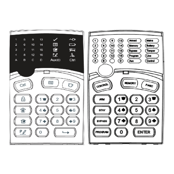
Page 20: Keypad Lcd Type Description
KEYPAD LCD Type Description There are two types of LCD Keypads available for the Crow Runner system. The LCD Keypad on the right has the Function Button Descriptions written in English (Textual), while the one on the left has Symbols to Describe their Functions. -
Page 21: How To Initiate A Panic Alarm
How to initiate a Panic Alarm Press simultaneously Buttons < > & < >. Must be Pressed Together How to initiate a Medical Alarm Press simultaneously Buttons < > & < >. Must be Pressed Together. How to initiate a Fire Alarm Press simultaneously Buttons <... -
Page 22: Summary Of Functions
Summary of Functions The system's main functions are listed below Function Textual Keypad Keys Symbol Keypad Keys Description Notes Full or Initiates full arm C O D E C O D E ENTER Partition Arm Full Arm Only if enabled ... - Page 23 Function Textual Keypad Keys Symbol Keypad Keys Description Notes Control Activates or Press <Control> deactivates outputs for 2 seconds Device# Device# CONTROL and devices ENTER Change or Activates program For details see ...
-
Page 24: How To Arm The System Before Exit
How to Arm the System before Exit Preparing the System for Arming Verify that there are No Zones indicated on the LCD Screen as open, when all zones are Sealed, (i.e.: all doors & windows are closed and motion in the protected areas is restricted or Zones bypassed), the system <Ready>... -
Page 25: Arming The System While Staying Home
Arming the System While Staying Home Arming the System in Stay Mode This type of Arming is used when people are present within the protected area. At nighttime, when the family is about to retire, perimeter zones are protected, but not the interior zones. Consequently, interior movements are ignored by the system. -
Page 26: How To Bypass Zones
How to Bypass Zones Bypass any zone that cannot be Sealed (closed). You can Bypass selected zones prior to arming. Bypass is also used to temporarily exclude a faulty zone from service, which requires repair. To bypass a selected zone, press <BYPASS> / , the ‘Bypass’... -
Page 27: Generate Threat Or Duress
Generate Threat or Duress If you are compelled to disarm the system under threat, you must enter the duress digit before the user’s code to activate the automatic dialer. The duress digit shifts up your usual code by one digit. If your code is 345 and 8 is your duress digit, than entering 8345 modifies your code. The modified duress code disarms the system in a normal way, but at the same time activates the dialer silently to report a “duress event”... -
Page 28: How To Control Outputs And Devices
EVENT TYPE DEVICE EVENT TYPE DEVICE ACTIVATION Zones 1-16 FIRE ALARM Keypad Fire (BUTTONS 4&6 ARE PRESSED TOGETHER) BYPASS Zones 1-16 MEDICAL ALARM Keypad Medical (BUTTONS 7&9 PRESSED TOGETHER) DETECTOR TAMPER Zones 1-8 ARMED A Area A is Armed (SHORT CIRCUIT) DETECTOR TAMPER Zones 9-16 ARMED B... -
Page 29: Entering The User Program/Client Mode (Using Lcd Keypad)
Entering the User Program/Client Mode (Using LCD Keypad) There are 2 levels of program modes, CLIENT mode and INSTALLER mode. Normally the installer configures the system to give you access to the CLIENT mode so you can add, delete, or change the user codes. To get into CLIENT mode (provided the system is NOT Armed) Press <PROGRAM>/ enter Master code and <ENTER>/ . -
Page 30: How To Add Or Change The User Code (Using Lcd Keypad)
How to Add or Change the User Code (Using LCD Keypad) While in CLIENT mode, press <PROGRAM>/ then 1E and the User number (2 to 100) you want to add or change, then press <ENTER>/ . If there is an existing code already in the system for that user, it will be displayed on the LCD Screen. -
Page 31: How To Operate The Access Control Output
How to Operate the Access Control Output If the alarm system has been set up to allow control of an electric door lock, you can activate the door release function as follows; Press <CONTROL>/ or Press <CONTROL>/ enter CODE then <ENTER>/ . -
Page 32: Using The Remote Command Control
telephone (digit) buttons) to force the Runner Panel to hang-up from your call and Immediately Report a Test Call to the Back-To-Base Monitoring Company. This function Must first be programmed (setup) by your systems installer. Please ask your systems installer for details. Using the Remote Command Control Another powerful feature available from your alarm is Command Control. -
Page 33: Using Local Command Control
15-second timer is active during the whole command control process so a period of 15 seconds without a key press causes the panel to hang-up. Using Local Command Control If a command control code for outputs is programmed and the output/s are allowed to be locally controlled from the keypad, then entering the 4 digit code at a keypad blanks the display and the LCD Screen now indicate the output status. -
Page 34: Adjusting Backlighting And Buzzer Tone
Button followed Immediately by repeatedly pressing on the “A”/ Button. This will increase the Frequency of the Crow LCD Keypad Buzzer. At some point, the frequency will be so high that we can No Longer Hear the Buzzer (i.e.: The Buzzer will turn Off). -
Page 35: Lcd Keypad In Local Edit Mode
“Output Names” (the Output name is displayed when viewing Output On/Off events in memory mode). Accessing Local Edit Mode To enter Local Edit Program Mode on a CROW LCD Keypad Press and Hold <CONTROL>/ followed Immediately by Pressing the <ARM>/ and hold both buttons down for seconds. -
Page 36: Lcd Keypad Local Edit Mode Menu Programming
LCD KEYPAD LOCAL EDIT MODE MENU PROGRAMMING The LCD Keypad Main menu headings for “Local Edit” program mode are listed on this page. On entering Local Edit Mode the display looks like the example below. To move to the next menu heading simply press the arrow. To move back to the previous heading simply press the Arrow. -
Page 37: Changing The Area Single Character Identifier
When you are at the desired main menu heading, press <ENTER>/ to access the data program location. See example below Changing the Area Single Character Identifier When you enter in [PROG] / -[998]-[ENTER]/ the display looks like the example above. You may edit the single character Area identifier at this address starting at Area “A” (first left-hand position). -
Page 38: Changing The Zone Names
(Remember that there are a maximum of 16 characters per program address). If you make a mistake use the “STAY (CROW)” button to move the cursor towards the left and make any corrections necessary. When you are happy with the text, press <ENTER>/ to save the changes. -
Page 39: Changing The Keypad Area Name
Changing the Keypad Area Name When you enter [PROG] / -[2001]-[ENTER] / the display looks like the example above. You may edit the Area Name at this location. The area name can be up to 16 characters long. If you program in a name for the area, this name is shown when displaying events in memory display mode. -
Page 40: Resetting All Text To Default
If you wished to return to the last saved version of the text simply press and hold the “A” button for two seconds and the last saved text for zone one is displayed. NOTE: If the last saved version of text for Zone 1 was in fact the default setting, then pressing “Control”... -
Page 42: Customization Chart
Customization Chart Use this form to record your changes and customizations. User Name User Name Zone Zone Name Device... -
Page 44: Product Support
Not be able to assist you as well as Your System’s Installer. If you have purchased a property with a Crow Alarm in it, you can download a User’s Guide for the model of Crow Alarm you have and if you would like to learn more about your system, you can contact one of Crow’s Authorized Distributors and ask them for a name of a Crow...
Need help?
Do you have a question about the Runner Series and is the answer not in the manual?
Questions and answers