Advertisement
Table of Contents
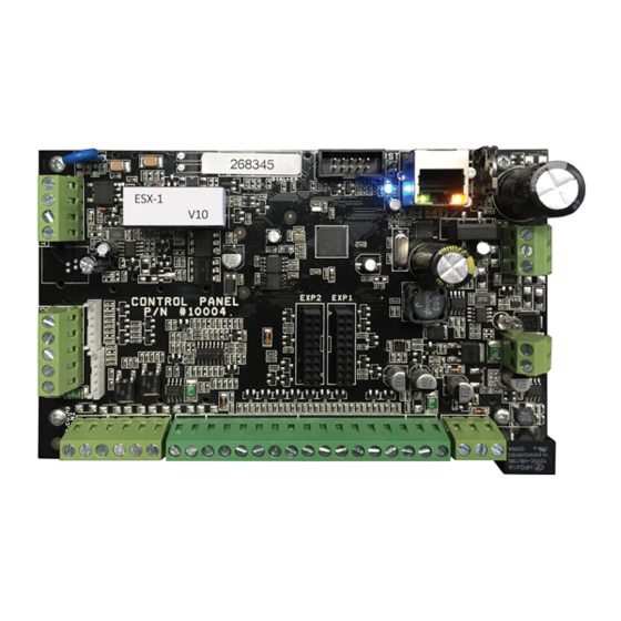
- 1 Connection Diagram
- 2 Runner-8 in Mini Box Specification
- 3 Connection Wiring Diagrams
- 4 Runner-16 in Mini Box Specification
- 5 Current Consumption
- 6 Maximum Current Drain Allowed from the Control Panel
- 7 Inputs/Outputs
- 8 Connection Diagram: RUNNER-PLUS
- 9 Runner - Plus Specification
- Download this manual
C
ONDENSED
ADDRESS
USER CODES 1 TO 100. Codes can be up to 6 digits. User 1 (Master
P1E 1-100E
Code) = 123
USER TYPE - Code/Radio/Access tag-Card
P2E 1-100E
0 = Keypad Code User (PIN)
1 = Radio User (Users 21-100 only)
2 = Access Tag/Card User
3 = Both Code and Access Tag/Card User (Tag + PIN)
4 = Either Code or Access Tag/Card User (Tag or PIN)
P3E 1-100E
USER AREA ASSIGNMENT. 1 = Area A, 2 = Area B
P4E 1-100E
USER CODE ACCESS OPTIONS
User 1-40 = 1,2,3,4,8
User 41,45,49,53,57, = 1,3,4,8
User 42,46,50,54,58 = 2,4,8
User 43,47,51,55,59 = 8, (Delay Panic – see P8E)
User 44,48,52,56,60 = 8, (O/P-4 control – see P12E 4E, P13 4E, P14E
4E)
User 61,66,71,76,81,86,91,96 = 3,4,8
User 62,67,72,77,82,87,92,97 = 1,8
User 63,68,73,78,83,88,93,98 = 2,8
User 64,69,74,79,84,89,94,99 = 8, (O/P-4 control – see P12E 4E, P13
4E, P14E 4E)
User 65,70,75,80,85,90,95,100 = 8, (Delay Panic – see P8E)
1 = Code can Arm Area
2 = Code can arm Stay Mode
3 = Code can Disarm Area
4 = Code can disarm Stay Mode
5 = Code is a Security Guard Code
6 = Code will Arm Latchkey Mode
7 = Call Divert Code
8 = User can View Event Memory
Runner Series
8/16 Z
W
ONE
IRELESS AND
V
ERSION
C
: R
OVERS
UNNER
P
ROGRAMMING
USER PROGRAMMING
DESCRIPTION
W
A
IRED
LARM
908.2 A
USTRALIA
-8, R
-16, R
UNNER
UNNER
(T
ECHNICIAN
C
P
ONTROL
ANEL
-P
LUS
'
) G
S
UIDE
DEFAULT
U1 = 123
U 1-40 = 4
U 41-100 = 1
U 1-100 = 1
NEW
1
Advertisement
Table of Contents


Need help?
Do you have a question about the RUNNER-8 and is the answer not in the manual?
Questions and answers