Table of Contents
Advertisement
Quick Links
Advertisement
Table of Contents

Subscribe to Our Youtube Channel
Related Manuals for AXIOMTEK eBOX530-820-FL Series


Summary of Contents for AXIOMTEK eBOX530-820-FL Series
- Page 1 Series Embedded System User’s Manual...
- Page 2 AXIOMTEK does not warrant or assume any legal liability or responsibility for the accuracy, completeness or usefulness of any information in this document. AXIOMTEK does not make any commitment to update the information in this manual.
-
Page 3: Safety Precautions
Safety Precautions Before getting started, please read the following important safety precautions. The eBOX530-820-FL does not come equipped with an operating system. An operating system must be loaded first before installing any software into the computer. Be sure to ground yourself to prevent static charge when installing the internal components. -
Page 4: Classification
Classification Degree of production against electric shock: not classified Degree of protection against the ingress of water: IPX0 Equipment not suitable for use in the presence of a flammable anesthetic mixture with air or with oxygen or nitrous oxide. Mode of operation: Continuous Type of protection against electric shock: Class I equipment General Cleaning Tips You may need the following precautions before you begin to clean the... - Page 5 a component. Although paper towels or tissues can be used on most hardware as well, we still recommend you to rub it with a piece of cloth. Water or rubbing alcohol: You may moisten a piece of cloth a bit with some water or rubbing alcohol and rub it on the computer.
-
Page 6: Scrap Computer Recycling
If the computer equipments need the maintenance or are beyond repair, we strongly recommended that you should inform your AXIOMTEK distributor as soon as possible for the suitable solution. For the computers that are no longer useful or no longer working well, please contact your AXIOMTEK distributor for recycling and we will make the proper arrangement. -
Page 7: Table Of Contents
Table of Contents Disclaimers ......................ii Safety Precautions ....................iii Classification ......................iv General Cleaning Tips ..................iv Scrap Computer Recycling .................vi CHAPTER 1 INTRODUCTION ..................1 General Description................. 1 System Specifications ................3 1.2.1 CPU....................3 1.2.2 I/O System..................3 1.2.3 System Specification ............... - Page 8 MEMO viii...
-
Page 9: Chapter 1 Introduction
Series User’s Manual CHAPTER 1 INTRODUCTION This chapter contains general information and detailed specifications of the eBOX530-820-FL. The Chapter 1 includes the following sections: General Description System Specification Dimensions I/O Outlets Package List General Description The eBOX530-820-FL is an embedded system that supports onboard ®... - Page 10 Series User’s Manual Reliable and Stable Design The eBOX530-820-FL adopts the advanced cooling system ™ and supporting the CompactFlash , which makes it especially suitable for vibration environments, best for industrial automation, digital signage and gaming application. Embedded O.S. Supported ®...
-
Page 11: System Specifications
Series User’s Manual System Specifications 1.2.1 ® ™ Onboard Intel ATOM Z510 (1.1 GHz) or Z530 (1.6 GHz) processors BIOS Phoenix-Award BIOS, 4Mbit with RPL/PXE LAN Boot ROM, SmartView and Customer CMOS Backup System Memory One 200-pin DDR2 400/533MHz SODIMM max. up to 2 GB 1.2.2... - Page 12 Series User’s Manual ~ 80 (-4 ºF ~ 176ºF) Humidity 10% ~ 90% (non-condensation) Vibration Endurance 1Grms w/ HDD (5 ~ 500Hz, X, Y, Z directions) Weight 0.5 kg (1.1 lb) Dimensions 130mm(5.11”) (W) x 95.4mm(3.75”) (D) x 47.1mm(1.85”) (H) NOTE All specifications and images are subject to change without notice.
-
Page 13: Dimensions
Series User’s Manual Dimensions The following diagrams show you dimensions and outlines of the eBOX530-820-FL. Introduction... -
Page 14: I/O Outlets
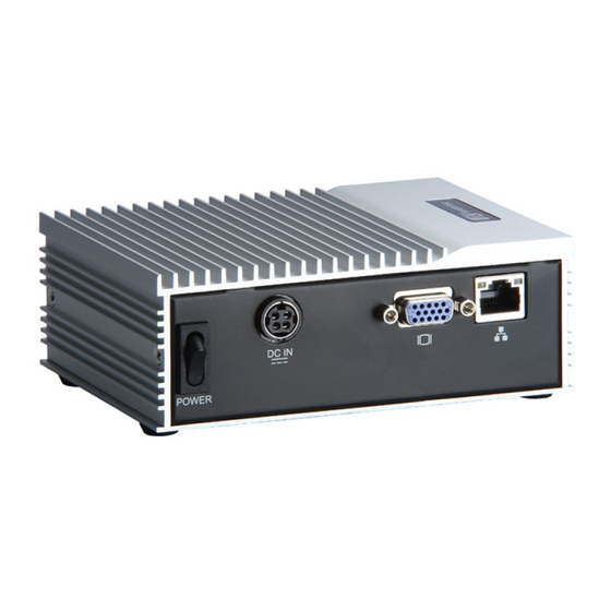
Series User’s Manual I/O Outlets The following figures show you I/O outlets on front view of the eBOX530-820-FL. Front View AUDIO 4 x USB 2.0 CONNECTORS CONNECTORS PS/2 CONNECTORS COM1/2 FOR KB/MS CONNECTORS Rear View 5V DC-IN POWER INPUT... - Page 15 Series User’s Manual SATA Connector The SATA connector is for high-speed SATA interface ports and each SATA connector supports a single SATA device. Signal SATA_TX+ SATA_TX- SATA_RX- SATA_RX+ Plug one end of the SATA cable to the SATA connector, and the other end of cable to the SATA hard drive.
-
Page 16: Packing List
Series User’s Manual Packing List The package bundled with your eBOX530-820-FL should contain the following items: eBOX530-820-FL System Unit x 1 eBOX530-820-FL Quick Manual x 1 Notice x1 Power Cord x 1 CD x 1 (For Driver and User’s Manual) - Page 17 Series User’s Manual MEMO Introduction...
-
Page 18: Chapter 2 Hardware Installation
Series User’s Manual CHAPTER 2 HARDWARE INSTALLATION The eBOX530-820-FL is convenient for your various hardware configurations, such as Memory Module, HDD (Hard Disk Drive), and CompactFlash card. The chapter 2 will show you how to install the hardware. It includes:... - Page 19 Series User’s Manual Step 3 Loosen these screws, and remove the back cover from the system. Step 4 Locate the memory module as marked. Hardware Installation...
- Page 20 Series User’s Manual Step 5 Hold one side of the module, and insert the gold colored contact into the socket. Push the module down. Step 6 The memory module is locked by two latches on the sides. NOTE While uninstalling the Memory Module, you need to...
- Page 21 Series User’s Manual stretch these two latches aside, and then take the module off the socket. Step 7 Put the cover back to the system, and fasten screws tight close the chassis. Hardware Installation...
-
Page 22: Installing The Hard Disk Drive
Series User’s Manual Installing the Hard Disk Drive ** NOTICE ** Two graphics drivers, but only one can be installed in eBOX530. Windows XP GMA 500 driver The default setting of display output under Windows XP GMA 500 driver is LVDS port. If you only connect VGA port to install driver, please press "Ctrl+Alt+F1"... - Page 23 Series User’s Manual Hardware Installation...
- Page 24 Series User’s Manual Step 3 Loosen these screws, and remove the back cover from the system. Step 4 HDD assembly parts include: HDD Bracket x 1 2.5 inch HDD x 1 Screws x 4 HDD Mylar x1 Screw the 2.5 inch HDD, together with the HDD Mylar, to the HDD bracket.
- Page 25 Series User’s Manual Step 5 Fix the HDD bracket into the system, and plug the power cable in HDD. Step 6 Put the cover back to the system, and fasten screws tight close the chassis. Hardware Installation...
-
Page 26: Installing The Compactflash
Series User’s Manual Installing the CompactFlash Card ** NOTICE ** Two graphics drivers, but only one can be installed in eBOX530. Windows XP GMA 500 driver The default setting of display output under Windows XP GMA 500 driver is LVDS port. If you only connect VGA port to install driver, please press "Ctrl+Alt+F1"... - Page 27 Series User’s Manual Hardware Installation...
- Page 28 Series User’s Manual Step 4 Locate the CompactFlash socket. Step 5 Insert the CompactFlash card into the socket until it is firmly seated. Hardware Installation...
- Page 29 Series User’s Manual Step 6 Put the cover back to the system, and fasten screws tight close the chassis. Hardware Installation...
-
Page 30: Installing Din Mount (Optional)
Series User’s Manual Installing DIN Mount (optional) The eBOX530-820-FL provides DIN Mount that customers can install as below: Step 1 Prepare DIN Mount assembling components (screws and bracket) ready. MAXIMUM DEPTH OF THE HDD BRACKET: 2.5mm Hardware Installation... - Page 31 Series User’s Manual Step 2 Assembly the bracket to the system, and fasten screws tight. Hardware Installation...
-
Page 32: Installing Rail Mount
Series User’s Manual Installing Rail Mount The eBOX530-820-FL provides Rail Mount that customers can install as below: Step 1 Prepare Rail Mount assembling components (screws and bracket) ready. Step 2 Assembly the bracket to the system, and fasten screws tight. - Page 33 Series User’s Manual MEMO Hardware Installation...
-
Page 34: Chapter 3 Phoenix-Award Bios Utility
Series User’s Manual CHAPTER 3 PHOENIX-AWARD BIOS UTILITY The Phoenix-Award BIOS provides users with a built-in Setup program to modify basic system configuration. All configured parameters are stored in a battery-backed-up RAM (CMOS RAM) to save the Setup information whenever the power is turned off. -
Page 35: Control Keys
Series User’s Manual Control Keys Up arrow Move cursor to the previous item Down arrow Move cursor to the next item Left arrow Move cursor to the item on the left hand Right arrow Move to the item in the right hand... -
Page 36: The Main Menu
Series User’s Manual The Main Menu Once you enter the Award BIOS CMOS Setup Utility, the Main Menu will appear on the screen. The Main Menu allows you to select from ten setup functions and two exit choices. Use the arrow keys to select the setup function you intend to configure then press <Enter>... -
Page 37: Standard Cmos Setup Menu
Series User’s Manual Standard CMOS Setup Menu The items in Standard CMOS Setup Menu are divided into several categories. Each category includes no, one or more than one setup items. Use the arrow keys to highlight the item and then use the <PgUp>... - Page 38 Series User’s Manual The categories identify the types of one channel that have been installed in the computer. There are 45 predefined types and 2 users definable types are for Enhanced IDE BIOS. Type 1 to Type 45 is predefined. Type User is user-definable.
-
Page 39: Advanced Bios Features
Series User’s Manual All, But The system boot will not stop for a keyboard or disk error; it will stop for all other errors. Disk/Key Press <Esc> to return to the Main Menu page. Advanced BIOS Features This section allows you to configure and improve your system and allows you to set up some system features according to your preference. - Page 40 Series User’s Manual CPU Feature Scroll to this item and press <Enter> to view the CPU Feature sub menu. Hard Disk Boot Priority Scroll to this item and press <Enter> to view the sub menu to decide the disk boot priority.
- Page 41 Series User’s Manual Quick Power On Self Test This option speeds up Power on Self Test (POST) after you turn on the system power. If set as Enabled, BIOS will shorten or skip some check items during POST. The default setting is “Enabled”.
-
Page 42: Advanced Chipset Features
Series User’s Manual MPS Version Control For OS This item specifies the version of the Multiprocessor Specification (MPS). Version 1.4 has extended configuration tables to improve support for multiple PCI bus configurations and provide future expandability. Press <Esc> to return to the Main Menu page. - Page 43 Series User’s Manual result. The default value is “Disabled”. Video BIOS Cacheable This item allows you to change the Video BIOS location from ROM to RAM. Video Shadow will increase the video speed. *** VGA Setting *** On-Chip Frame Buffer Size Use this item to set the VGA frame buffer size.
-
Page 44: Integrated Peripherals
Series User’s Manual Integrated Peripherals This section allows you to configure your OnChip IDE Device, Onboard Device and SuperIO Device. OnChip IDE Device Scroll to this item and press <Enter> to view the sub menu OnChip IDE Device. Phoenix-Award BIOS Utility... - Page 45 Series User’s Manual IDE HDD Block Mode Block mode is also called block transfer, multiple commands, or multiple sectors read/write. If your IDE hard drive supports block mode (most new drives do), select Enabled for automatic detection of the optimal number of block read/writes per sector the drive can support.
- Page 46 Series User’s Manual USB Device Setting Scroll to this item and press <Enter> to view the sub menu USB Device Setting. Onboard Serial Port 1/2 Select an address and corresponding interrupt for the serial port. There are several options for your selection.
-
Page 47: Power Management Setup
Series User’s Manual Power Management Setup The Power Management Setup allows you to save energy of your system effectively. It will shut down the hard disk and turn OFF video display after a period of inactivity. ACPI Function This item allows you to enable/disable the Advanced Configuration and Power Management (ACPI). - Page 48 Series User’s Manual powered while most other hardware components turn off to save energy. The information stored in memory will be used to restore the system when a “wake up” event occurs. Power Management This option allows you to select the type (or degree) of power saving for Doze, Standby, and Suspend modes.
- Page 49 Series User’s Manual Suspend Mode After the selected period of system inactivity (1 minute to 1 hour), all devices except the CPU shut off. The default value is “Disabled”. System will never enter SUSPEND mode Disabled Defines the continuous idle time before the system entering SUSPEND mode.
-
Page 50: Pnp/Pci Configuration Setup
Series User’s Manual 3.10 PnP/PCI Configuration Setup This section describes configuring the PCI bus system. PCI, or Personal Computer Interconnect, is a system which allows I/O devices to operate at speeds nearing the speed the CPU itself uses when communicating with its own special components. - Page 51 Series User’s Manual IRQ Resources When resources are controlled manually, assign each system interrupt to one of the following types in accordance with the type of devices using the interrupt: 1. Legacy ISA Devices compliant with the original PC AT bus...
-
Page 52: Pc Health Status
Series User’s Manual 3.11 PC Health Status This section supports hardware monitoring that lets you monitor those parameters for critical voltages, temperatures and fan speed of the board. System Component Characteristics These items provide you with information about the system’s current operating status. -
Page 53: Frequency/Voltage Control
Series User’s Manual 3.12 Frequency/Voltage Control This section is to control the CPU frequency and Supply Voltage, DIMM OverVoltage and AGP voltage. CPU Clock Ratio Use this item to select the CPU’s frequency. Press <Esc> to return to the Main Menu page. -
Page 54: Load Optimized Defaults
Series User’s Manual 3.13 Load Optimized Defaults This option allows you to load the default values to your system configuration. These default settings are optimal and enable all high performance features. To load SETUP defaults value to CMOS SRAM, enter “Y”. If not, enter “N”. -
Page 55: Set Supervisor/User Password
Series User’s Manual 3.14 Set Supervisor/User Password You can set a supervisor or user password, or both of them. The differences between them are: Supervisor password: You can enter and change the options on the setup menu. User password: You can just enter, but have no right to change the options on the setup menu. -
Page 56: Save & Exit Setup
Series User’s Manual 3.15 Save & Exit Setup This allows you to determine whether or not to accept the modifications. Typing “Y” quits the setup utility and saves all changes into the CMOS memory. Typing “N” brigs you back to Setup utility. -
Page 57: Exit Without Saving
Series User’s Manual 3.16 Exit Without Saving Select this option to exit the Setup utility without saving the changes you have made in this session. Typing “Y” will quit the Setup utility without saving the modifications. Typing “N” will return you to Setup utility. -
Page 58: Chapter 4 Installation Of Drivers
Series User’s Manual CHAPTER 4 INSTALLATION OF DRIVERS The device drivers are located on the Product Information CD-ROM that comes with the package. The auto-run function of drivers will guide you to install the utilities and device drivers under a Windows system. - Page 59 Series User’s Manual ® An Intel License Agreement appears to show you the important information. Click “Yes” to next step. Please wait while running the following setup operations. (3-1) Installation of Drivers...
- Page 60 Series User’s Manual (3-2) Click “Finish” to complete the setup process. Installation of Drivers...
-
Page 61: Installing Vga Driver
Series User’s Manual You will be asked to reboot your computer when the installation is completed. Please click “Yes, I want to restart my computer now” if you don’t need to install any other drivers. Otherwise, please click “No, I will restart my computer later”, and go on next step. - Page 62 Series User’s Manual ® An Intel License Agreement appears to show you the important information. Click “Yes” to next step. The message of Readme File Information appears to show you the system requirements and installation information. Please click “Next”.
- Page 63 Series User’s Manual 4. Please wait while running the following setup operations. 5. When this message appears, please click “Next”. Installation of Drivers...
- Page 64 Series User’s Manual 6. You will be asked to reboot your computer when the installation is completed. Please click “Yes, I want to restart my computer now” if you don’t need to install any other drivers. Otherwise, please click “No, I will restart my computer later”, and click “Finish”...
-
Page 65: Installing Lan Driver
Series User’s Manual Installing LAN Driver Run the InstallShield Wizard for Ethernet from the driver directory in your driver CD. Click “Next” to next step. Click “Install” to start the installation. Installation of Drivers... - Page 66 Series User’s Manual Please wait while running the following installation operation. Click “Finish” to complete the installation. Installation of Drivers...
-
Page 67: Installing Audio Driver
Series User’s Manual Installing Audio Driver 1. Run the InstallShield Wizard for Audio from the driver directory in your driver CD. Click “Next” to next step. Installation of Drivers... - Page 68 Series User’s Manual 2. Please wait while running the following installation operation. Installation of Drivers...
- Page 69 Series User’s Manual 3. You will be asked to reboot your computer when the installation is completed. Please click “Yes, I want to restart my computer now” if you don’t need to install any other drivers. Otherwise, please click “No, I will restart my computer later”, and click “Finish”...
Need help?
Do you have a question about the eBOX530-820-FL Series and is the answer not in the manual?
Questions and answers