Table of Contents
Advertisement
Quick Links
Advertisement
Table of Contents

Related Manuals for AXIOMTEK EP100


Summary of Contents for AXIOMTEK EP100
- Page 1 EP100 AMD Embedded G-Series Processor EPIC Board User’s Manual...
-
Page 2: Disclaimers
Axiomtek does not make any commitment to update the information in this manual. Axiomtek reserves the right to change or revise this document and/or product at any time without notice. No part of this document may be reproduced, stored in a retrieval system, or transmitted, in any form or by any means, electronic, mechanical, photocopying, recording, or otherwise, without the prior written permission of Axiomtek Co., Ltd. -
Page 3: Esd Precautions
Wear a wrist-grounding strap, available from most electronic component stores, when handling boards and components. Trademarks Acknowledgments Axiomtek is a trademark of Axiomtek Co., Ltd. ® Windows is a trademark of Microsoft Corporation. AMI is trademark of American Megatrend Inc. -
Page 4: Table Of Contents
Table of Contents Disclaimers ...................... ii ESD Precautions ..................... iii Chapter 1 Introduction ..........1 Features ....................1 Specifications ..................2 Utilities Supported ................3 Chapter 2 Board and Pin Assignments ....5 Board Dimensions and Fixing Holes ..........5 Board Layout .................. - Page 5 2.4.17 VGA Connector (CN20) ................24 2.4.18 SIM Card Slot (SCN2) ................25 2.4.19 Serial ATA Connectors (SATA1 and SATA2) ..........25 2.4.20 USB Stacks (USB1 and USB2) ..............26 CFast™ Socket (SCF1) ................26 2.4.21 2.4.22 Ethernet Ports (LAN1) ................27 Chapter 3 Hardware Description ......
- Page 6 This page is intentionally left blank.
-
Page 7: Chapter 1 Introduction
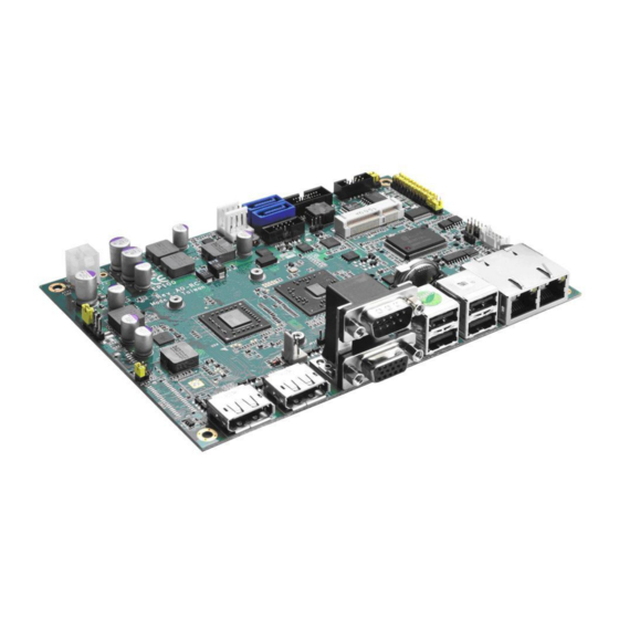
EP100 AMD Embedded G-Series Processor EPIC Board with LVDS Chapter 1 Introduction The EP100, an EPIC board, supports AMD G-Series APU T56N/T40R. The board integrates the FCH A50M and delivers outstanding system performance through high-bandwidth interfaces, multiple I/O functions for interactive applications and various embedded computing solutions. -
Page 8: Specifications
EP100 AMD Embedded G-Series Processor EPIC Board with LVDS Specifications AMD G-Series APU dual core T56N 1.65GHz. AMD G-Series APU single core T40R 1.0GHz. Thermal Solution With AMD G-Series APU dual core T56N 1.65GHz is fan solution ... -
Page 9: Utilities Supported
EP100 AMD Embedded G-Series Processor EPIC Board with LVDS Form Factor EPIC form factor. Note: All specifications and images are subject to change without notice. Utilities Supported Chipset and graphic driver Ethernet driver (RTL8111E) Audio driver ... - Page 10 EP100 AMD Embedded G-Series Processor EPIC Board with LVDS This page is intentionally left blank. Introduction...
-
Page 11: Board And Pin Assignments
EP100 AMD Embedded G-Series Processor EPIC Board with LVDS Chapter 2 Board and Pin Assignments Board Dimensions and Fixing Holes Top Side Board and Pin Assignments... - Page 12 EP100 AMD Embedded G-Series Processor EPIC Board with LVDS Bottom Side Side View Board and Pin Assignments...
- Page 13 EP100 AMD Embedded G-Series Processor EPIC Board with LVDS Slim Type Board and Pin Assignments...
-
Page 14: Board Layout
EP100 AMD Embedded G-Series Processor EPIC Board with LVDS Board Layout Top Side Board and Pin Assignments... - Page 15 EP100 AMD Embedded G-Series Processor EPIC Board with LVDS Bottom Side Board and Pin Assignments...
-
Page 16: Jumper Settings
And remove jumper clip from 2 jumper pins to open. Below illustration shows how to set up jumper. Properly configure jumper settings on the EP100 to meet your application purpose. Below you can find a summary table of all jumpers and onboard default settings. -
Page 17: Audio Output Selection (Jp1)
EP100 AMD Embedded G-Series Processor EPIC Board with LVDS 2.3.1 Audio Output Selection (JP1) JP1 is to select line out or speaker out as source of audio output on audio connector CN2. When speaker out is used, it delivers 1W/channel continuous at 8 Ohm loads. -
Page 18: Com1 Data/Power Selection (Jp6)
EP100 AMD Embedded G-Series Processor EPIC Board with LVDS 2.3.5 COM1 Data/Power Selection (JP6) The COM1 port has +5V level power capability on DCD and +12V level on RI by setting this jumper. When COM1 is set to +5V or +12V level, please make sure the communication mode is RS-232 (see section 2.3.6). -
Page 19: Auto Power On (Jp11)
EP100 AMD Embedded G-Series Processor EPIC Board with LVDS 2.3.8 Auto Power On (JP11) If JP11 is enabled for power input, the system will be automatically power on without pressing soft power button. If JP11 is disabled for power input, it is necessary to manually press soft power button to power on the system. -
Page 20: Connectors
EP100 AMD Embedded G-Series Processor EPIC Board with LVDS Connectors Signals go to other parts of the system through connectors. Loose or improper connection might cause problems, please make sure all connectors are properly and firmly connected. Here is a summary table which shows all connectors on the hardware. -
Page 21: Power Connector (Atx1)
EP100 AMD Embedded G-Series Processor EPIC Board with LVDS 2.4.1 Power Connector (ATX1) The ATX1 is a 4-pin power supply interface. External power supply plug fits into ATX1 in only one orientation. Properly press down power supply plug until it completely and firmly fits into this connector. -
Page 22: Com3 And Com4 Connector (Cn3)
EP100 AMD Embedded G-Series Processor EPIC Board with LVDS 2.4.4 COM3 and COM4 Connector (CN3) Both COM 3 and COM 4 ports have +5V level power capability on DCD and 12V level on RI by setting JP2 and JP3, respectively (see section 2.3.2 and 2.3.3). The pin assignments are listed on the following table. -
Page 23: Pci-Express Mini Card Socket (Cn7 And Scn1)
EP100 AMD Embedded G-Series Processor EPIC Board with LVDS 2.4.6 PCI-Express Mini Card Socket (CN7 and SCN1) Both CN7 and SCN1 are PCI-Express Mini Card sockets which support PCI-Express x1 link and USB 2.0 link. A PCI-Express Mini Card can be applied to either PCI-Express or USB 2.0. -
Page 24: Digital I/O Port Connector (Cn8)
EP100 AMD Embedded G-Series Processor EPIC Board with LVDS SCN1 Signal Signal WAKE# +3.3VSB No use No use +1.5V CLKREQ# REFCLK- REFCLK+ No use No use W_DISABLE# PERST# PE_RXN3 +3.3VSB PE_RXP3 +1.5V SMB_CLK PE_TXN3 SMB_DATA PE_TXP3 USB_D8- USB_D8+ +3.3VSB +3.3VSB... -
Page 25: Inverter Connector (Cn9)
EP100 AMD Embedded G-Series Processor EPIC Board with LVDS 2.4.8 Inverter Connector (CN9) The CN9 is a DF13-8S-1.25C 8-pin connector for inverter. We strongly recommend you to use the matching DF13-8S-1.25C connector to avoid malfunction. Signal VBL1 (+12V level) VBL1 (+12V level) -
Page 26: Lvds Connector (Cn13)
EP100 AMD Embedded G-Series Processor EPIC Board with LVDS 2.4.10 LVDS Connector (CN13) This board has a 40-pin connector CN13 for LVDS LCD interface. It is strongly recommended to use the matching JST SHDR-40VS-B 40-pin connector for LVDS interface. Pin 1~6 VCCM can be set to +3.3V level or +5V level or +12V level by setting JP10 or JP12 (see section 2.3.7). - Page 27 EP100 AMD Embedded G-Series Processor EPIC Board with LVDS 18-bit dual channel 24-bit single channel Signal Signal Signal Signal VCCM VCCM VCCM VCCM VCCM VCCM VCCM VCCM VCCM VCCM VCCM VCCM N.C. N.C. N.C. N.C. N.C. Channel B D0- N.C.
-
Page 28: Smbus Connector (Cn14)
EP100 AMD Embedded G-Series Processor EPIC Board with LVDS 2.4.11 SMBus Connector (CN14) This connector is for SMBus interface support. The SMBus (System Management Bus) is a simple 2-wire bus for the purpose of lightweight communication. Most commonly it is used for communication with the power source related applications such as on/off instructions. -
Page 29: Com1 Connector (Cn17A)
EP100 AMD Embedded G-Series Processor EPIC Board with LVDS Power On/Off Button Pin 9 and 10 connect the power button on front panel to the CPU board, which allows users to turn on or off power supply. System Reset Switch Pin 11 and 12 connect the case-mounted reset switch that reboots your computer without turning off the power switch. -
Page 30: Displayport Connector (Cn18 And Cn19)
EP100 AMD Embedded G-Series Processor EPIC Board with LVDS 2.4.16 DisplayPort Connector (CN18 and CN19) Two DisplayPort interfaces are available through connectors CN18 (DisplayPort 0) and CN19 (DisplayPort 1). Signal DPB_LANE0 DPB_LANE0# DPB_LANE1 DPB_LANE1# DPB_LANE2 DPB_LANE2# DPB_LANE3 DPB_LANE3# Detect Pin... -
Page 31: Sim Card Slot (Scn2)
2.4.18 SIM Card Slot (SCN2) SCN2 is on the bottom side of the EP100 for Inserting SIM Card. In order to work properly, the SIM Card must be used together with Mini Card which is inserted to socket SCN1. It is mainly used in 3G wireless network application. -
Page 32: Usb Stacks (Usb1 And Usb2)
EP100 AMD Embedded G-Series Processor EPIC Board with LVDS 2.4.20 USB Stacks (USB1 and USB2) The board features Universal Serial Bus (USB) connectors, compliant with USB 2.0 (480Mbps) that can be adapted to any USB peripheral, such as monitor, keyboard and mouse. -
Page 33: Ethernet Ports (Lan1)
EP100 AMD Embedded G-Series Processor EPIC Board with LVDS 2.4.22 Ethernet Ports (LAN1) The LAN1 has dual RJ-45 ethernet connectors. Connection can be established by plugging one end of the ethernet cable into this RJ-45 connector and the other end (phone jack) to a 1000/100/10-Base-T hub. - Page 34 EP100 AMD Embedded G-Series Processor EPIC Board with LVDS This page is intentionally left blank. Board and Pin Assignments...
-
Page 35: Chapter 3 Hardware Description
7 and Linux environments. The system performance depends on the APU. BIOS The EP100 uses AMI Plug and Play BIOS with a single 16Mbit SPI Flash. System Memory The EP100 supports one 204-pin DDR3 SO-DIMM sockets for a maximum memory of 4GB DDR3 SDRAMs. -
Page 36: I/O Port Address Map
EP100 AMD Embedded G-Series Processor EPIC Board with LVDS I/O Port Address Map The AMD G-Series APU communicates via I/O ports. Total 1KB port addresses are available for assigning to other devices via I/O expansion cards. Hardware Description... - Page 37 EP100 AMD Embedded G-Series Processor EPIC Board with LVDS Hardware Description...
-
Page 38: Interrupt Controller (Irq) Map
EP100 AMD Embedded G-Series Processor EPIC Board with LVDS Interrupt Controller (IRQ) Map The EP100 is 100% PC compatible control board which consists of 20 interrupt request lines. Four out of 20 can be programmable. The mapping list of the 20 interrupt request lines is shown as the following table. -
Page 39: Memory Map
EP100 AMD Embedded G-Series Processor EPIC Board with LVDS Memory Map The memory mapping list is shown as follows: Hardware Description... - Page 40 EP100 AMD Embedded G-Series Processor EPIC Board with LVDS This page is intentionally left blank. Hardware Description...
-
Page 41: Ami Bios Setup Utility
EP100 AMD Embedded G-Series Processor EPIC Board with LVDS Chapter 4 AMI BIOS Setup Utility The AMI UEFI BIOS provides users with a built-in setup program to modify basic system configuration. All configured parameters are stored in a 16MB flash chip to save the setup information whenever the power is turned off. -
Page 42: Main Menu
EP100 AMD Embedded G-Series Processor EPIC Board with LVDS Hot Keys Description Left/Right The Left and Right <Arrow> keys allow you to select a setup screen. The Up and Down <Arrow> keys allow you to select a setup screen or ... -
Page 43: Advanced Menu
EP100 AMD Embedded G-Series Processor EPIC Board with LVDS System Language Use this item to choose the system default language. System Date/Time Use this option to change the system time and date. Highlight System Time or System Date using the <Arrow> keys. Enter new values through the keyboard. Press the <Tab>... - Page 44 EP100 AMD Embedded G-Series Processor EPIC Board with LVDS ACPI Settings You can use this screen to select options for the ACPI configuration, and change the value of the selected option. A description of the selected item appears on the right side of the screen.
- Page 45 EP100 AMD Embedded G-Series Processor EPIC Board with LVDS CPU Configuration This screen shows the CPU Configuration. Node 0 Information View memory information related to Node 0. AMI BIOS Setup Utility...
- Page 46 EP100 AMD Embedded G-Series Processor EPIC Board with LVDS IDE Configuration In the IDE Configuration menu, you can see the currently installed hardware in the SATA ports. During system boot up, the BIOS automatically detects the presence of SATA devices.
- Page 47 EP100 AMD Embedded G-Series Processor EPIC Board with LVDS USB Configuration You can use this screen to select options for the USB Configuration, and change the value of the selected option. A description of the selected item appears on the right side of the screen.
- Page 48 EP100 AMD Embedded G-Series Processor EPIC Board with LVDS W83627UHG Super IO Configuration You can use this screen to select options for the Super IO Configuration, and change the value of the selected option. A description of the selected item appears on the right side of the screen.
- Page 49 EP100 AMD Embedded G-Series Processor EPIC Board with LVDS H/W Monitor This screen monitors hardware health status. This screen displays the temperature of system and CPU, cooling fan speed in RPM and system voltages (VCORE, +12V, +5V and +3.3V).
-
Page 50: Chipset Menu
EP100 AMD Embedded G-Series Processor EPIC Board with LVDS Chipset Menu The Chipset menu allows users to change the advanced chipset settings. You can select any of the items in the left frame of the screen to go to the sub menus: ►... - Page 51 EP100 AMD Embedded G-Series Processor EPIC Board with LVDS North Bridge Configuration This screen allows users to configure parameters of North Bridge chipset. Memory Configuration All of options are set Auto as default. AMI BIOS Setup Utility...
- Page 52 EP100 AMD Embedded G-Series Processor EPIC Board with LVDS Node 0 Information This item is to provide user with the information of current using DDR3 SDRAMs. AMI BIOS Setup Utility...
- Page 53 EP100 AMD Embedded G-Series Processor EPIC Board with LVDS North Bridge LVDS Config Select DP0 Output Mode Use this item to enable LVDS or Display Port0. DP1 Output Mode Use this item to choose Display Port1 output or disable mode.
- Page 54 EP100 AMD Embedded G-Series Processor EPIC Board with LVDS South Bridge This screen allows users to configure South Bridge chipset. For items marked with “”, please press <Enter> for more options. ► SB SATA Configuration ► SB USB Configuration ►...
- Page 55 EP100 AMD Embedded G-Series Processor EPIC Board with LVDS SB SATA Configuration Use this item to select options for SATA configuration. OnChip SATA Channel Use this item to enable or disable SATA channel. OnChip SATA Type Here are the options: Native IDE and AHCI.
- Page 56 EP100 AMD Embedded G-Series Processor EPIC Board with LVDS SB USB Configuration Use this item to enable or disable all of USB devices. SB HD Azalia Configuration This item allows you to enable or disable HD audio Azalia device.
-
Page 57: Boot Menu
EP100 AMD Embedded G-Series Processor EPIC Board with LVDS Boot Menu The Boot menu allows users to change boot options of the system. Setup Prompt Timeout Number of seconds to wait for setup activation key. 65535(0xFFFF) means indefinite waiting. -
Page 58: Security Menu
EP100 AMD Embedded G-Series Processor EPIC Board with LVDS Security Menu The Security menu allows users to change the security settings for the system. Administrator Password This item indicates whether an administrator password has been set (installed or uninstalled). -
Page 59: Save & Exit Menu
EP100 AMD Embedded G-Series Processor EPIC Board with LVDS Save & Exit Menu The Save & Exit menu allows users to load your system configuration with optimal or fail-safe default values. Save Changes and Exit When you have completed the system configuration changes, select this option to leave Setup and return to Main Menu. - Page 60 EP100 AMD Embedded G-Series Processor EPIC Board with LVDS Discard Changes Select this option to quit Setup without making any permanent changes to the system configuration. Select Discard Changes from the Save & Exit menu and press <Enter>. Select Yes to discard changes.
-
Page 61: Appendix A Watchdog Timer
EP100 AMD Embedded G-Series Processor EPIC Board with LVDS Appendix A Watchdog Timer About Watchdog Timer Software stability is major issue in most application. Some embedded systems are not watched by human for 24 hours. It is usually too slow to wait for someone to reboot when computer hangs. -
Page 62: Sample Program
EP100 AMD Embedded G-Series Processor EPIC Board with LVDS Sample Program Assembly sample code : ;Enable WDT: dx,2Eh al,87 ;Un-lock super I/O dx,al dx,al ;Select Logic device: dx,2Eh al,07h dx,al dx,2Fh al,08h dx,al ;Activate WDT: dx,2Eh al,30h dx,al dx,2Fh al,01h dx,al ;Set Second or Minute :... - Page 63 EP100 AMD Embedded G-Series Processor EPIC Board with LVDS If N=08h, the time base is set to minute. M = time value 00: Time-out Disable 01: Time-out occurs after 1 minute 02: Time-out occurs after 2 minutes 03: Time-out occurs after 3 minutes...
- Page 64 EP100 AMD Embedded G-Series Processor EPIC Board with LVDS This page is intentionally left blank. Watchdog Timer...
-
Page 65: Appendix B Digital I/O
EP100 AMD Embedded G-Series Processor EPIC Board with LVDS Appendix B Digital I/O About Digital I/O The onboard digital I/O has 8 bits (DIO0~7). Each bit can be set to function as input or output by software programming. In default, all pins are pulled high with +5V level (according to main power). - Page 66 EP100 AMD Embedded G-Series Processor EPIC Board with LVDS ;Programming DIO as in/out. dx,2Eh al,0E0h dx,al dx,2Fh al,Nh ;If N=07h, DIO is programmed as 3 inputs Note1 dx,al ;and 5 outputs (see below Digital Input: ;Read digital input data. dx,2Eh...
- Page 67 EP100 AMD Embedded G-Series Processor EPIC Board with LVDS When DIO0~2 are connected to external device, the device sets DIO0~2 to high DIO7 DIO6 DIO5 DIO4 DIO3 DIO2 DIO1 DIO0 Output Output Output Output Output When DIO0~2 are connected to external device, the device sets DIO0 to low and DIO1~2 to high...
- Page 68 EP100 AMD Embedded G-Series Processor EPIC Board with LVDS This page is intentionally left blank. Digital I/O...
Need help?
Do you have a question about the EP100 and is the answer not in the manual?
Questions and answers