
Related Manuals for AXIOMTEK ETM831 Series


Summary of Contents for AXIOMTEK ETM831 Series
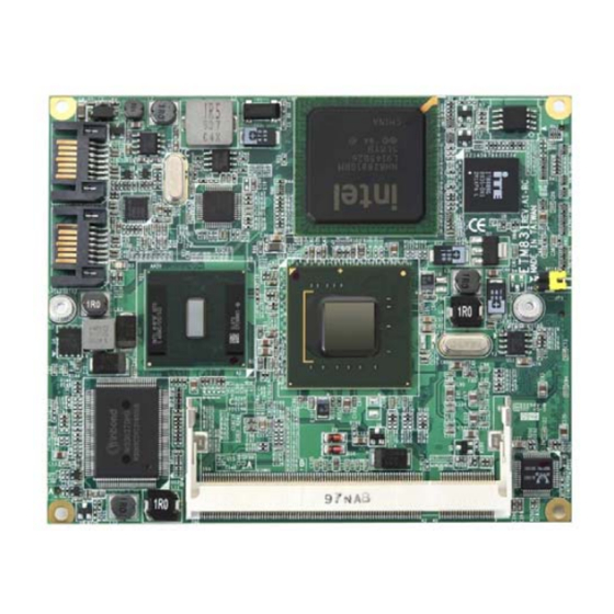
- Page 1 ETM831 Series ® Intel Atom™ ETX v3.01 SoM Multiple I/O Features With User’s Manual...
- Page 2 AXIOMTEK does not warrant or assume any legal liability or responsibility for the accuracy, completeness or usefulness of any information in this document. AXIOMTEK does not make any commitment to update the information in this manual.
-
Page 3: Esd Precautions
Wear a wrist-grounding strap, available from most electronic component stores, when handling boards and components. Trademarks Acknowledgments AXIOMTEK is a trademark of AXIOMTEK Co., Ltd. ® Windows is a trademark of Microsoft Corporation. AMI are trademarks of American Megatrend Inc. -
Page 4: Table Of Contents
Table of Contents Disclaimers ..................ii ESD Precautions ................iii C h a p t e r 1 ..................1 Introduction ..................1 Specifications.............. 2 Utilities Supported............4 C h a p t e r 2 ..................5 Board Layout and Connectors............5 Board Layout and Fixing Holes........ - Page 5 Chipset Menu............49 Exit Menu ..............53 A p p e n d i x A ................55 Watchdog Timer ................55 Using the Watchdog Function ............ 56...
-
Page 7: Chapter 1
C h a p t e r 1 Introduction The ETM831 Series is a finest embedded ETX system-on-a-module in the market, which makes a generic interface to connect the module to peripherals such as hard disk, mouse, and display. It supports ®... -
Page 8: Specifications
ETM831 All-In-One ETX v3.01 SoM User’s Manual Specifications ® CPU: Intel Atom™ N270 1.6GHz/512KB L2 cache processor CPU Frequency: FSB533MHz ® System Chipset: Intel 945GSE and ICH7M BIOS AMI BIOS, Y2K compliant 8Mbit SPI Flash, DMI, Plug and Play RPL/PXE Ethernet Boot ROM SmartView for multiple LCD type selection, display mode option and application extension features “Load Optimized Default”... - Page 9 ETM831 All-In-One ETX v3.01 SoM User’s Manual Expansion Interface Four PCI Bus Masters supported One Full ISA supported Ethernet One RTL8103EL Fast Ethernet controller Audio 5.1 channel HD Codec Audio (optional) Realtek ALC662, HD audio MIC-in, Line-in, Line-out Power Management ACPI (Advanced Configuration and Power Interface) Form Factor ETX form factor 95 mm x114 mm...
-
Page 10: Utilities Supported
ETM831 All-In-One ETX v3.01 SoM User’s Manual Utilities Supported Chipset Driver VGA Driver Ethernet Driver Audio Driver Introduction... -
Page 11: Chapter 2
ETM831 All-In-One ETX v3.01 SoM User’s Manual C h a p t e r 2 Board Layout and Connectors Board Layout and Fixing Holes Component Side Hardware Description... - Page 12 ETM831 All-In-One ETX v3.01 SoM User’s Manual Solder Side Hardware Description...
-
Page 13: Board Dimensions
ETM831 All-In-One ETX v3.01 SoM User’s Manual Board Dimensions Component Side Hardware Description... - Page 14 ETM831 All-In-One ETX v3.01 SoM User’s Manual Solder Side Hardware Description...
-
Page 15: Heatspreader Installation
ETM831 All-In-One ETX v3.01 SoM User’s Manual Heatspreader Installation There is a protective plastic covering on the thermal pads. This must be removed before the heatspreader can be mounted. Each heatspreader is designed for a specific ETM module. The thermal pads on the heatspreader are designed to make contact with the necessary components on the ETM module. - Page 16 ETM831 All-In-One ETX v3.01 SoM User’s Manual Figure 2: ETM831 Thermal Solution Design Guide Hardware Description...
-
Page 17: Connectors & Jumper Settings
Connectors connect the CPU card with other parts of the system. Loose or improper connection might cause problems. Make sure all connectors are properly and firmly connected. Here is a summary table shows you all connectors on the ETM831 Series. Connectors Label... -
Page 18: Etx Connector - X1: Cns3
ETM831 All-In-One ETX v3.01 SoM User’s Manual 2.4.1 ETX Connector – X1: SCN3 Description Description PCICLK3 PCICLK4 PCICLK1 PCICLK2 PCI_REQ3# PCI_GNT3# PCI_GNT2# VCC3 PCI_REQ2# PCI_GNT1# PCI_REQ1# VCC3 PCI_GNT0# CPUFAN_IN SERIRQ PCI_REQ0# PCI_AD0 VCC3 PCI_AD1 PCI_AD2 PCI_AD4 PCI_AD3 PCI_AD6 PCI_AD5 PCI_C/BE0# PCI_AD7 PCI_AD8 PCI_AD9... - Page 19 ETM831 All-In-One ETX v3.01 SoM User’s Manual Description Description PCI_PERR# CPUFAN_OUT PCI_PME# USB2- PCI_LOCK# PCI_DEVSEL# PCI_TRDY# USB3- PCI_IRDY# PCI_STOP# PCI_FRAME# USB2+ PCI_AD16 PCI_C/BE2# PCI_AD17 USB3+ PCI_AD19 PCI_AD18 PCI_AD20 USB0- PCI_AD22 PCI_AD21 PCI_AD23 USB1- PCI_AD24 PCI_C/BE3# PCI_AD25 PCI_AD26 PCI_AD28 USB0+ PCI_AD27 PCI_AD29 PCI_AD30 USB1+...
-
Page 20: Etx Connector - X2: Cns1
ETM831 All-In-One ETX v3.01 SoM User’s Manual 2.4.2 ETX Connector – X2: SCN1 Description Description ISA_SD14 ISA_SD15 ISA_SD13 MASTER# ISA_SD12 DREQ7 ISA_SD11 DACK7# ISA_SD10 DREQ6 ISA_SD9 DACK6# ISA_SD8 DREQ5 ISA_MEMW# DACK5# ISA_MEMR# DREQ0 ISA_LA17 DACK0# ISA_LA18 IRQ14 ISA_LA19 IRQ15 ISA_LA20 IRQ12 ISA_LA21 IRQ11... - Page 21 ETM831 All-In-One ETX v3.01 SoM User’s Manual Description Description ISA_SA7 IRQ6 ISA_SA8 IRQ7 ISA_SA9 SYSCLK ISA_SA10 REFRESH# ISA_SA11 DREQ1 ISA_SA12 DACK1# ISA_SA13 DREQ3 ISA_SA14 DACK3# ISA_SA15 IOR# ISA_SA16 IOW# ISA_SA18 ISA_SA17 ISA_SA19 SMEMR# IOCHRDY ISA_SD0 SMEMW# ISA_SD2 ISA_SD1 ISA_SD3 N0WS# DREQ2 ISA_SD4 ISA_SD5...
-
Page 22: Etx Connector - X3: Cns4
ETM831 All-In-One ETX v3.01 SoM User’s Manual 2.4.3 ETX Connector – X3: SCN4 Description Description BLUE HSYNC GREEN VSYNC DDCK DDDA LVDSB_CLK- LVDSB_DATA3- LVDSB_CLK+ LVDSB_DATA3+ LVDSB_DATA1+ LVDSB_DATA2+ LVDSB_DATA1- LVDSB_DATA2- LVDSA_DATA3- LVDSB_DATA0+ LVDSA_DATA3+ LVDSB_DATA0- LVDSA_DATA2- LVDSA_CLK+ LVDSA_DATA2+ LVDSA_CLK- LVDSA_DATA0+ LVDSA_DATA1+ LVDSA_DATA0- LVDSA_DATA1- L_DDC_DAT L_DDC_CLK... - Page 23 ETM831 All-In-One ETX v3.01 SoM User’s Manual Description Description PD7/N.C IRRX ERR#/HDSEL# IRTX PD6/N.C RXD2 INIT#/DIR# RTS2# PD5/N.C DTR2# SLIN#/STEP# DCD2# PD4/DSKCHG# DSR2# PD3/RDATA# CTS2# PD2/WP# TXD2# PD1/TRK0# RI2# PD0/INDEX# RXD1 ACK#/DRV RTS1# BUSY#/MOT DTR1# PE/WDATA# DCD1# SLCT#/WGATE# DSR1# MSCLK CTS1# MSDAT TXD1#...
-
Page 24: Etx Connector - X4: Cns2
ETM831 All-In-One ETX v3.01 SoM User’s Manual 2.4.4 ETX Connector – X4: SCN2 Description Description 5VSB PWGIN PS_ON SPEAKER PWRBTN# RTC_BATTERY RSMRST# ACTLED SPEEDLED I2CLK OVCR# SMBDAT SMBCLK SMBDAT DASP_S PIDE_CS3# PIDE_CS1# IDE_PDIAG_S PIDE_A2# PIDE_A0# PIDE_A1# PIDE_INTRQ PIDE_ACK# PIDE_RDY PIDE_IOR# PIDE_IOW# PIDE_DRQ Hardware Description... - Page 25 ETM831 All-In-One ETX v3.01 SoM User’s Manual Description Description PIDE_D15 PIDE_D0 PIDE_D14 PIDE_D1 PIDE_D13 PIDE_D2 PIDE_D12 PIDE_D3 PIDE_D11 PIDE_D4 PIDE_D10 PIDE_D5 PIDE_D9 PIDE_D6 RING# CBLID_P# LAN_RX- PIDE_D8 LAN_RX+ LAN_TX- PIDE_D7 LAN_TX+ HDRST# -- End of ETX Connector-X4 (SCN2) Pin Assignment Table -- Hardware Description...
-
Page 26: 7-Pin Sata Connectors: Sata1, Sata2
ETM831 All-In-One ETX v3.01 SoM User’s Manual 2.4.5 7-pin SATA Connectors: SATA1, SATA2 These SATA connectors are for high-speed SATA interface ports and they can be connected to hard disk devices. Description SATA1,SATA2 2.4.6 Audio Connector: SFC1(Optional) The audio connector is for six channel HD interface ports and they can be connected to audio jack. -
Page 27: 2.4.7 Auto Power On Jumper: Jp1
ETM831 All-In-One ETX v3.01 SoM User’s Manual 2.4.7 Auto Power On Jumper: JP1 When Jumper JP1 is set OPEN for AC power input, the system will be automatically power ON without pressing soft power button; when JP1 is SHORT for AC power input, it is necessary to manually press soft power button to make the system power ON. -
Page 28: Chapter 3
Vista, Windows XP, Windows Embedded Standard, Windows XP Embedded, Linux and QNX. BIOS The ETM831 Series uses AMI Plug and Play BIOS with a single 8Mbit SPI Flash, DMI, Plug and Play. System Memory The ETM831 Series industrial CPU card supports one 200-pin unbuffered DDR2 SO-DIMM socket for a maximum memory of 2GB DDR2 SDRAMs. - Page 29 ETM831 All-In-One ETX v3.01 SoM User’s Manual Hardware Description...
- Page 30 ETM831 All-In-One ETX v3.01 SoM User’s Manual Hardware Description...
-
Page 31: Interrupt Controller
ETM831 All-In-One ETX v3.01 SoM User’s Manual Interrupt Controller The ETM831 Series is a 100% PC compatible control board. It consists of 16 interrupt request lines, and four out of them can be programmable. The mapping list of the 16 interrupt request lines is shown as the following table. -
Page 32: Chapter 4
ETM831 All-In-One ETX v3.01 SoM User’s Manual CHAPTER 4 AMI BIOS SETUP UTILITY This chapter provides users with detailed description how to set up basic system configuration through the AMIBIOS8 BIOS setup utility. Starting To enter the setup screens, follow the steps below: 1. -
Page 33: Main Menu
ETM831 All-In-One ETX v3.01 SoM User’s Manual Main Menu When you first enter the Setup Utility, you will enter the Main setup screen. You can always return to the Main setup screen by selecting the Main tab. There are two Main Setup options. They are described in this section. -
Page 34: Advanced Menu
ETM831 All-In-One ETX v3.01 SoM User’s Manual Advanced Menu The Advanced menu allows users to set configuration of the CPU and other system devices. You can select any of the items in the left frame of the screen to go to the sub menus: CPU Configuration IDE Configuration SuperIO Configuration... - Page 35 ETM831 All-In-One ETX v3.01 SoM User’s Manual AMI BIOS Utility...
- Page 36 ETM831 All-In-One ETX v3.01 SoM User’s Manual Configure advanced CPU settings This screen shows the CPU Configuration, and you can change the value of the selected option. Execute-Disable Bit Capability This item helps you enable or disable the No-Execution Page Protection Technology. Hyper Threading Technology Use this item to enable or disable Hyper-Threading Technology, which makes a single physical processor...
- Page 37 ETM831 All-In-One ETX v3.01 SoM User’s Manual Enhanced C-States This item allows you to enable or disable any available enhanced C-states ( C1E, C2E, C3E, C4E and Hard C4E). IDE Configuration You can use this screen to select options for the IDE Configuration, and change the value of the selected option.
- Page 38 ETM831 All-In-One ETX v3.01 SoM User’s Manual Legacy IDE Channels When the ATA/IDE Configuration is set to Compatible, this item will be displayed. Primary/Secondary/Third IDE Master/Slave Select one of the hard disk drives to configure IDE devices installed in the system by pressing <Enter> for more options.
- Page 39 ETM831 All-In-One ETX v3.01 SoM User’s Manual OnBoard Floppy Controller Use this item to enable or disable the onboard floppy drive controller. Serial Port1 Address This item specifies the base I/O port address and Interrupt Request address of serial port 1. The Optimal setting is 3F8/IRQ4.
- Page 40 ETM831 All-In-One ETX v3.01 SoM User’s Manual Hardware Health Configuration This screen shows the Hardware Health Configuration, and a description of the selected item appears on the right side of the screen. System Temperature/CPU Temperature These items display the temperature of CPU and System, Vcore, etc.
- Page 41 ETM831 All-In-One ETX v3.01 SoM User’s Manual ACPI Settings You can use this screen to select options for the ACPI Settings, and change the value of the selected option. A description of the selected item appears on the right side of the screen. AMI BIOS Utility...
- Page 42 ETM831 All-In-One ETX v3.01 SoM User’s Manual General ACPI Configuration Scroll to this item and press <Enter> to view the General ACPI Configuration sub menu, which contains General ACPI (Advanced Configuration and Power Management Interface) options for your configuration. Award BIOS Utility...
- Page 43 ETM831 All-In-One ETX v3.01 SoM User’s Manual Advanced ACPI Configuration Scroll to this item and press <Enter> to view the Advanced ACPI Configuration sub menu, which contains Advanced ACPI (Advanced Configuration and Power Management Interface) options for your configuration. AMI BIOS Utility...
- Page 44 ETM831 All-In-One ETX v3.01 SoM User’s Manual APM Configuration You can use this screen to select options for the APM Configuration, and change the value of the selected option. A description of the selected item appears on the right side of the screen.
- Page 45 ETM831 All-In-One ETX v3.01 SoM User’s Manual Video Power Down Mode This option specifies the Power State that the video subsystem enters when the BIOS places it in a power saving state after the specified period of display inactivity has expired. The default setting is Suspend.
- Page 46 ETM831 All-In-One ETX v3.01 SoM User’s Manual Suspend Time Out (Minute) This option specifies the length of time the system This setting prevents the system waits before it enters from entering suspend mode. This is the default setting. suspend mode. The default setting is Disabled Set this item to allow the...
- Page 47 ETM831 All-In-One ETX v3.01 SoM User’s Manual *** Advanced Resume Event Controls *** Resume On Ring This item enables or disables the function of Resume On Ring that resumes the system through incoming calls. Resume On RTC Alarm You can set “Resume On RTC Alarm” item to enabled and key in Data/time to power on system.
- Page 48 ETM831 All-In-One ETX v3.01 SoM User’s Manual MPS Configuration This screen shows the MPS (Multi Processor Specification) Configuration, and you can change its value. A description of the selected item appears on the right side of the screen. MPS Revision Use this item to select MPS (Multi Processor Specification) Revision 1.1 or 1.4.
- Page 49 ETM831 All-In-One ETX v3.01 SoM User’s Manual USB Configuration You can use this screen to select options for the USB Configuration, and change the value of the selected option. A description of the selected item appears on the right side of the screen.
-
Page 50: Pci Pnp Menu
ETM831 All-In-One ETX v3.01 SoM User’s Manual PCI PnP Menu The PCI PnP menu allows users to change the advanced settings for PCI/PnP devices. Clear NVRAM Use this item to clear the data in the NVRAM (CMOS). Here are the options for your selection, No and Yes. Plug &... -
Page 51: Boot Menu
ETM831 All-In-One ETX v3.01 SoM User’s Manual Boot Menu The Boot menu allows users to change boot options of the system. You can select any of the items in the left frame of the screen to go to the sub menus: Boot Settings Configuration LAN Boot Option For items marked with “... - Page 52 ETM831 All-In-One ETX v3.01 SoM User’s Manual Boot Settings Configuration Quick Boot Enabling this item lets the BIOS skip some power on self tests (POST). The default setting is Enabled. AddOn ROM Display Mode This item selects the display mode for option ROM. The default setting is Force BIOS.
- Page 53 ETM831 All-In-One ETX v3.01 SoM User’s Manual PS/2 Mouse Support This item determines if the BIOS should reserve IRQ12 for the PS/2 mouse or allow other devices to make use of this IRQ. Here are the options for your selection, Auto, Enabled and Disabled.
-
Page 54: Security Menu
ETM831 All-In-One ETX v3.01 SoM User’s Manual Security Menu The Security menu allows users to change the security settings for the system. Supervisor Password This item indicates whether a supervisor password has been set. If the password has been installed, Installed displays. -
Page 55: Chipset Menu
ETM831 All-In-One ETX v3.01 SoM User’s Manual Chipset Menu The Chipset menu allows users to change the advanced chipset settings. You can select any of the items in the left frame of the screen to go to the sub menus: North Bridge Configuration South Bridge Configuration For items marked with “... - Page 56 ETM831 All-In-One ETX v3.01 SoM User’s Manual North Bridge Configuration DRAM Frequency This item allows you to control the Memory Clock. Configure DRAM Timing by SPD This item can enable or disable DRAM timing by SPD (Serial Presence Detect) device, which is a small EEPROM chip on the memory module, containing important information about the module speed, size, addressing mode and various parameters.
- Page 57 ETM831 All-In-One ETX v3.01 SoM User’s Manual Boot Graphic Adapter Priority This item allows you to select the graphics controller as the primary boot device. Internal Graphics Mode Select This item allows you to select the amount of system memory used by the internal graphics device. Video Function Configuration Press <Enter>...
- Page 58 ETM831 All-In-One ETX v3.01 SoM User’s Manual application. Boot Display This item is to select Display Device that the screen will be shown. Panel Scaling This item shows the setting of panel scaling and operates the scaling function that the panel output can fit the screen resolution connected to the output port.
-
Page 59: Exit Menu
ETM831 All-In-One ETX v3.01 SoM User’s Manual Exit Menu The Exit menu allows users to load your system configuration with optimal or failsafe default values. Save Changes and Exit When you have completed the system configuration changes, select this option to leave Setup and reboot the computer so the new system configuration parameters can take effect. - Page 60 ETM831 All-In-One ETX v3.01 SoM User’s Manual Load Optimal Defaults It automatically sets all Setup options to a complete set of default settings when you select this option. The Optimal settings are designed for maximum system performance, but may not work best for all computer applications.
-
Page 61: Watchdog Timer
ETM831 All-In-One ETX v3.01 SoM User’s Manual A p p e n d i x A Watchdog Timer Watchdog Timer Setting After the system stops working for a while, it can be auto-reset by the Watchdog Timer. The integrated Watchdog Timer can be set up in the system reset mode by program. -
Page 62: Using The Watchdog Function
ETM831 All-In-One ETX v3.01 SoM User’s Manual Using the Watchdog Function Start ↓ Un-Lock WDT: O 2E 87 ; Un-lock super I/O O 2E 87 ; Un-lock super I/O ↓ Select Logic device: O 2E 07 O 2F 00 Set WDT Funtion : O 2E 2B O 2F C0 Select Logic device:... - Page 63 ETM831 All-In-One ETX v3.01 SoM User’s Manual 1sec 50sec 180sec 992sec 2sec 55sec 190sec 2012sec 3sec 60sec 200sec 3032sec 4sec 65sec 210sec 3992sec 5sec 70sec 220sec 5012sec 6sec 75sec 230sec 6032sec 7sec 80sec 240sec 6992sec 8sec 85sec 250sec 8012sec 10sec 100sec 272sec 9032sec...
Need help?
Do you have a question about the ETM831 Series and is the answer not in the manual?
Questions and answers