Table of Contents
Advertisement
Advertisement
Table of Contents

Related Manuals for C&K systems S802


Summary of Contents for C&K systems S802
-
Page 1: Installation Manual
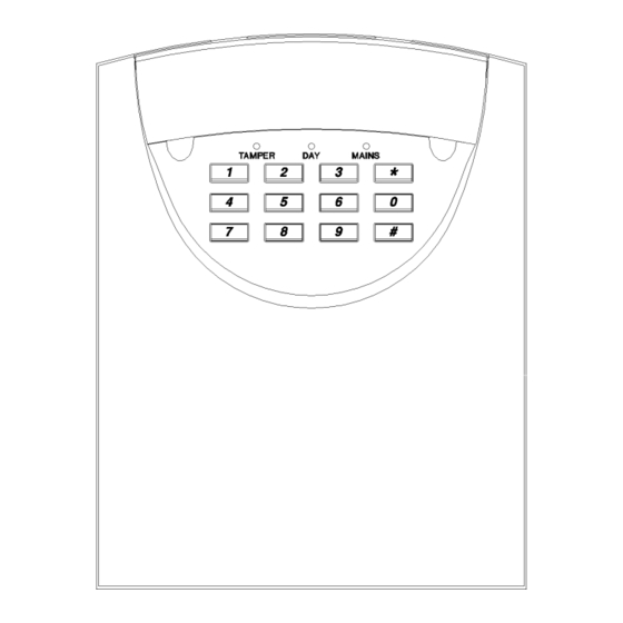
INSTALLATION MANUAL SECURIT 802 CONTROL PANEL S802... -
Page 2: Table Of Contents
CONTENTS Warnings Standards Warranty Statement Product Description Available Parts Intended use Specifications Processor Version Power Supply Keypads General Factory Defaults Installation Mounting Wiring Battery Detector Circuits L as Latch Line L as ID- Internal Sounders External Devices Strobe Keyswitch Connections Aux DC power Mounting Keypads Wiring Keypads... -
Page 3: Warnings
WARNINGS Prolonged short circuit of any supply can cause damage to the unit. Take the necessary precautions in not allowing liquids to spill on or into the unit. STANDARDS This unit conforms to ECD 89/336/EEC & LVD 73/23/EEC. This unit has been tested and has proven to meet all current emission and immunity regulations as set out by the EEC. -
Page 4: Specifications
SPECIFICATIONS There now follows the specifications of the panel. These include power consumption, panel dimensions etc. PROCESSOR VERSION SPECIFICATION FOR SOFTWARE REVISION NUMBER V1.0 The software revision number is located on the top of the main processor POWER SPECIFICATION SUPPLY Power Supply Mains Supply Voltage 230 V AC Nominal... -
Page 5: Installation
INSTALLATION INSTALLATION When fitting the panel, make sure to site it somewhere that is not visible from an PROCEDURES outside location ( Window or Door ) and also make sure that the panel is going to be accessible. An ideal location would be a cupboard in a hall or under stairs located close to the main entrance. -
Page 6: Internal Sounders
Detector reset (L+ when programmed for ID) DETECTOR RESET Some detectors require the removal of power to reset (e.g. Viper Plus or Smoke ® detectors). The L+ terminal can be programmed to be used as an 'ID' output using option 7-4. The L+ terminal should then be used as the negative supply for these devices. -
Page 7: Mounting Keypads
MOUNTING A REMOTE KEYPAD MOUNTING REMOTE KEYPADS Locate the position for your keypad then mark the holes for mounting. Make sure the cable is run through the backbox. Screw the backbox in the agreed position making sure it is not twisted. WIRING REMOTE KEYPADS... -
Page 8: Programming
If programming is not required simply close any lids that are open and press the # key. This will exit engineering mode. Now refer to the users manual for customer PROGRAMMING NEEDED? options. EXIT If at any time you wish to exit engineering mode, confirm any options you have ENGINEERING selected with the * (STAR) key, then close ALL tamper circuits and wait for MODE... -
Page 9: Bell Duration
SOUNDER DURATION (sounder ring time) 3-2 (Range 3-20 minutes) SOUNDER DURATION Enter 3-2. This has been preset to a factory default of 15 minutes. A new time may be programmed by entering one key from the following table. Press * to confirm the selection. -
Page 10: Circuit Programming
CIRCUIT PROGRAMMING 4 (Range 2-7) CIRCUIT PROGRAMMING Circuits 2 - 7 can be reprogrammed to suit your requirements. Circuit 1 is fixed as a Final exit circuit. Circuit 8 has limited options. ENTER PROGRAM ZONE ENTER PROGRAM ZONE 4 - 2 4 - 6 4 - 3 4 - 7... -
Page 11: Engineer Access Code
By pressing the keys 1-8 on the keypad you will select which zones you want ISOLATED during home set. As a key is pressed, its relevant LED on the display will toggle on or off. Any LED’s that are ON will be ISOLATED during home set and any that are off will remain ACTIVE. -
Page 12: Restoring Default Codes
FACTORY PROGRAMMING DEFAULTS 9-9 FACTORY DEFAULTS Factory defaults have been split into two sections, programming and codes. RESTORE DEFAULT To return to factory programming defaults first enter Engineering Mode then PROGRAMMING proceed as follows:- Enter 9-9 Any extension sounders will give a rapid pipping sound. The internal keypad sounder will emit a steady tone. - Page 13 NIGHT SET ENTRY GLOSSARY This means when the panel is NIGHT SET the zone, when activated, will start the entry OF TERMS timer but if the panel is FULL SET then this zone will simply act as an ALARM zone ENTRY CIRCUIT This will start the entry timer when activated providing the panel is set.
-
Page 14: Information Table
KEYS ENTERED ZONE ZONE USE / RESISTANCE LOCATION Ω Ω Ω Ω Ω Ω Ω Ω Ω Ω Ω Ω Ω Ω Ω Ω TIMER VALUE KEYS ENTERED FULL SECONDS NIGHT SECONDS EXT SOUNDER MINUTES TICK BOX 1 2 3 4 5 6 7 8 CHECKED EXTENDED OPTIONS BATTERY VOLTAGE... -
Page 15: Fault Finding
FAULT FINDING A selection of common known problems and solutions are listed below. Problem Cause Answer Programmed 7-5 but zone 1 Have not MANUALLY isolated When night setting enter wont isolate in night set. zone when setting panel. code * 0 * 1. Zone 1 is permanently lit Memory default link is on. - Page 16 C&K Systems Ltd. Unit 23-24 Walkers Road North Moons Moat Industrial Estate Redditch Worcs. Approved B98 9HE Tel: 01527 68111 Fax: 01527 68222 Tech Support:0345 660533 9am-5pm Weekdays (UK ONLY) BS EN ISO No.9002:1994 email to: info@cksys.co.uk Certificate No. 0944 website: http://users.powernet.co.uk/cksys 5-051-519-01...
Need help?
Do you have a question about the S802 and is the answer not in the manual?
Questions and answers
How do we reset the alarm when 8 is showing. We think it may have occurred after a power cut.
To reset the C&K Systems S802 alarm when it shows 8, follow these steps:
1. Enter engineering mode by inputting the engineer code.
2. Place the small link (supplied with the spare fuses) on the "Memory Default" link, located left of the LEDs near the top of the PCB.
3. Remove both mains and battery power.
4. Wait a few seconds, then reconnect the battery first, followed by the mains.
5. The speaker will emit an accept tone, and the factory user code defaults will be restored.
6. Remove the link; the zone 1 light will go out.
This restores the factory programming defaults while keeping the user and engineer codes unchanged.
This answer is automatically generated