Table of Contents
Advertisement
Film-Tech
The information contained in this Adobe Acrobat pdf
file is provided at your own risk and good judgment.
These manuals are designed to facilitate the
exchange of information related to cinema
projection and film handling, with no warranties nor
obligations from the authors, for qualified field
service engineers.
If you are not a qualified technician, please make no
adjustments to anything you may read about in these
Adobe manual downloads.
www.film-tech.com
Advertisement
Chapters
Table of Contents
Troubleshooting

Related Manuals for NEC NC2500S DLP CInema


Summary of Contents for NEC NC2500S DLP CInema
- Page 1 Film-Tech The information contained in this Adobe Acrobat pdf file is provided at your own risk and good judgment. These manuals are designed to facilitate the exchange of information related to cinema projection and film handling, with no warranties nor obligations from the authors, for qualified field service engineers.
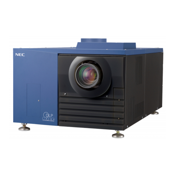
- Page 2 DLP Cinema Projector Installation Manual NEC Viewtechnology, Ltd.
- Page 3 Introduction DLP Cinema Projector Installation and Adjustment NEC Viewtechnology, Ltd. Manual (This document) describes the procedures to install, adjust and maintain the projector and peripheral devices. For safe and correct installation, adjustment and use of the projector, carefully read this document before installation. Refer to the operation manuals of the applicable products for basic operation and remarks of the projector.
- Page 4 DLP Cinema Projector Installation manual NC2500S...
-
Page 5: Important Information
NC2500S Important Information WARNING DOC compliance Notice TO PREVENT FIRE OR SHOCK HAZARDS, This Class A digital apparatus meets DO NOT EXPOSE THIS UNIT TO RAIN all requirements of the Canadian Interference- OR MOISTURE. ALSO DO NOT USE THIS Causing Equipment Regulations. UNIT’S POLARIZED PLUG WITH AN WARNING EXTENSION CORD RECEPTACLE OR... - Page 6 NC2500S Important Information Warning Connect the projector to exhaust Lamp power supply setup equipment. conditions • Use a duct, etc., to connect the projector’s • The location where you setup the air outlet to exhaust equipment that lamp power supply should have plenty can handle flow amounts of at least 16 of space in front of the air inlet and air /min.
- Page 7 NC2500S Important Information 3. Use a blower or lens paper to clean Please consult your dealer for the lens, and be careful not to more information. Do not attempt scratch or mar the lens. to stack projectors on the ceiling. Power Supply Fire and Shock Precautions...
- Page 8 NC2500S Important Information CAUTION CAUTION: High Pressure Lamp May Explode if Improperly Handled. Refer Never unplug the projection head power Servicing to Qualified Service Personnel. plug from the outlet or disconnect the breaker connected to the AC power Lamp Caution: Please cord of the lamp power supply unit under the following conditions.
-
Page 9: Table Of Contents
NC2500S Table of Contents Table of Contents Important Information ..................A-2 Table of Contents ....................A-6 1 1. Before Setting Up Your Projector ..........A-8 Lamp power supply unit installation conditions ....... A-8 Power supply construction specifiCautions ........A-10 Exhaust equipment specifiCautions..........A-12 Selecting Primary/Anamorphic Lenses for Your Projector ..... - Page 10 NC2500S Table of Contents 3.4.1 Display the test pattern ................ A-39 3.4.2 Adjusting the screen ratio ..............A-39 Mounting and adjusting the anamorphic ........A-41 3.5.1 Mounting the anamorphic ..............A-41 3.5.2 Adjusting the anamorphic lens position ........... A-42 3.5.3 Adjusting the anamorphic lens inclination..........
-
Page 11: Before Setting Up Your Projector
Before Setting Up Your Projector Lamp power supply unit installation conditions The location where you install the lamp power supply unit must have a plenty of space in front of the air inlet and air outlet to prevent the inside of that unit from becoming excessively hot. - Page 12 NC2500S 1. Before Setting Up Your Projector Example where the lamp power supply unit is installed to the Pedestal (NC-PD01) Air outlet opening area (duct structure): 48400mm or more Air inlet opening area: 36000mm or more Unit ; mm For installation procedure, refer to “2.2.1 Mounting a lamp power supply unit to the pedestal” (Page A-20).
-
Page 13: Power Supply Construction Specificautions
NC2500S 1. Before Setting Up Your Projector Power supply construction specifications Make sure to observe the contents described in this section. * Entrust a specialist to carry out the power supply work from the power supply equipment of the building to the place of projector installation. 3-phase AC power supply equipment (Star connection) Input voltage... - Page 14 NC2500S 1. Before Setting Up Your Projector Input voltage selection switch - Set the input voltage selection switch for the lamp power supply corresponding to the voltage of the AC power supply used. Set it as follows: AC power supply voltage used Switch setting 200V-230V 200V...
-
Page 15: Exhaust Equipment Specificautions
NC2500S 1. Before Setting Up Your Projector Exhaust equipment specifications It is necessary to connect the air outlet of the projector to the exhaust equipment. accessory protective sheet should also be mounted because the area around the air outlet can become very hot. For Exhaust equipment Installation, see “2.7. Mounting the exhaust equipment”... -
Page 16: Selecting Primary/Anamorphic Lenses For Your Projector
NC2500S 1. Before Setting Up Your Projector Selecting Primary/Anamorphic Lenses for Your Projector This section provides guideline information on how to select a screen size and projector mounting position appropriate for your presentation purposes and about selection of types of lenses as well. -
Page 17: Selection Of Primary Lens
NC2500S 1. Before Setting Up Your Projector Available Anamorphic Lenses Screen mask type Screen Type Anamorphic lens Remarks Horizontal moving SCOPE ×1.25 VISTA - HDTV - Vertical moving SCOPE ×1.25 or None No anamorphic lens should be used if the zooming power of the primary lens is insufficient. - Page 18 NC2500S 1. Before Setting Up Your Projector Projected Images The anamorphic lens works to magnify projected images horizontally when you use a wide screen for projection (SCOPE). How to Calculate the Magnification of Primary Lens SCOPE projection: Primary lens Length of projection (L) magnification = Screen width (W) ÷Anamorphic lens magnification Use 1x for anamorphic lens magnification if this lens is not in use.
-
Page 19: Removing The Projector Covers
NC2500S 1. Before Setting Up Your Projector Removing the projector covers You can remove covers of the projector by opening hexagonal fasteners. As shown below, a projector has 9 covers: Name of the cover B; Top rear cover I; Lamp change door A;... -
Page 20: Top Rear Cover Removal Procedure
NC2500S 1. Before Setting Up Your Projector 1.5.1 Top rear cover removal procedure Remove the top front cover of the projector. Remove the hexagonal fasteners at the top (at 4 places) and remove the front (lens side) cover. Open the top rear cover of the projector and place it on the top of the projector once. -
Page 21: Top Cover Mounting Procedure
NC2500S 1. Before Setting Up Your Projector 1.5.2 Top cover mounting procedure Place the top rear cover of the projector once on the top of the projector. Place it at a position where the cables from rear status indicators can be connected. -
Page 22: Setting Up Your Projector
Setting Up Your Projector Setup procedure Set up the projector according to the procedure below. This chapter describes the installation procedure until turning on of the power. -Step1 Projector installation (See page A-20) -Step2 Connecting the power cord (See page A-22) -STEP3 Mounting the primary lens (See page A-29) - STEP4... -
Page 23: Projector Installation
NC2500S 2. Settifng Up Your Projector Projector installation Move the projector to the projection position and install it corresponding to the screen and projection conditions. By mounting an exclusive pedestal (NC-PD01 separately sold) and tilt feet, you can adjust the tilting angle. For adjustment of the tilting angle, refer to the pedestal (NC-PD01) manual. To correct the inclination to the right or left of the projector, use the level adjusters at 4 positions. - Page 24 NC2500S 2. Settifng Up Your Projector Remove two M10x20 screws fastening the bottom of the back on the pedestal. Put the lamp power supply unit into the back of the pedestal. This work should be executed by two or more workers.
-
Page 25: Connecting The Power Cord
NC2500S 2. Settifng Up Your Projector Connecting the power cord Connect the power cords of the lamp power supply unit and the projector. • Carefully read the contents described in this section before connection and connect the cords according to the proper procedure. Inappropriate handling may cause fatal, serious or other bodily injuries due to fire or electric shock. -
Page 26: Removing The Covers Of The Projector And Lpsu
NC2500S 2. Settifng Up Your Projector 2.3.1 Removing the covers of the projector and LPSU To connect the power cord, remove the covers of the projector and the lamp power supply unit (LPSU). Remove the top front cover of the projector. Remove the hexagonal fasteners at the top (at 4 places) and remove the front (lens side) cover. -
Page 27: Connecting The 3-Phase Ac Power Cord To The Lpsu
NC2500S 2. Settifng Up Your Projector 2.3.2 Connecting the 3-phase AC power cord to the LPSU Entrust a specialist to carry out the AC power supply work from the power supply equipment of the building to the place of projector installation. This document describes the connection procedure for the lamp power supply unit (LPSU) assuming that the AC power supply construction has been completed. - Page 28 NC2500S 2. Settifng Up Your Projector Insert the grounding cable into the connection terminal and fix it with screws. Connect the exclusive interface cable to the projector and the lamp power supply unit. Connect the lamp power supply cord to the LPSU and the projector.
- Page 29 NC2500S 2. Settifng Up Your Projector Check the setting of the input power selection switch. Check that the switch is properly set to the voltage of the AC power supply used. • Make sure to check that the input power supply selection switch of the lamp power supply unit is set properly.
-
Page 30: Connecting The Power Cord Of The Projector
NC2500S 2. Settifng Up Your Projector 2.3.3 Connecting the power cord of the projector Insert the power cord (1φ) of the projector main unit into the power cord inlet. Any power cord (single-phase) for the main unit is not attached as accessory. Use a cord suitable to the user environment. - Page 31 NC2500S 2. Settifng Up Your Projector Mount the top rear cover of the projector. Mount the hexagonal fasteners (2 places) at the top. Before mounting the top rear cover, it is necessary to connect the cables of the rear status indicator. For details, refer to “1.5.2.
-
Page 32: Mounting The Primary Lens
NC2500S 2. Settifng Up Your Projector Mounting the primary lens Mount the attached lens holder (NC-PH01) before mounting the primary lens to the projector. Remove the lens holder mounting screws (4 pieces). The lens holder is separated into two parts. Mount the lower part of the lens holder along the lens insertion guide. - Page 33 NC2500S 2. Settifng Up Your Projector Tighten the fixing screws (2 screws) for the lens holder. The lens is fixed. Connect the control signal cable. Mount the front covers (top and bottom) of the projector. Mount the sponge attached to the lens after screen ratio adjustment.
-
Page 34: Mounting The Anamorphic Lens Motorized Turret
NC2500S 2. Settifng Up Your Projector Mounting the anamorphic lens motorized turret Use an optional anamorphic lens for projection of cinemascope size. Anamorphic lens motorized turret (separately sold: NC-AT01) is required for mounting of the anamorphic lens. 2.5.1 List of accessories attached to turret - Lens carriage 1peice - Slide pole 2pieces - Slide pole fixing screw 4pieces... -
Page 35: Mount The Turret
NC2500S 2. Settifng Up Your Projector 2.5.3 Mount the turret Remove the anamorphic lens mounting covers (2 places) of the projector. You will find fixing holes on the right and left of the front cover (bottom). On the opposite side of the lens, you will see a socket for the control 」... -
Page 36: Installation Of Small Iris (Information For Service Personnel
NC2500S 2. Settifng Up Your Projector Installation of Small Iris (Information for Service Personnel) If it is requested by the customer to reduce the projector's lamp luminance because it is too bright even when set to the minimum level, you may reduce it as follows. This operation will also improve the contrast ratio. - Page 37 NC2500S 2. Settifng Up Your Projector Remount the iris plate now attached with the small iris to the engine block. Use 4 screws you have removed at Step 2 to mount the iris plate. Mount the lens side cover to the projector. A-34...
-
Page 38: Mounting The Exhaust Equipment
NC2500S 2. Settifng Up Your Projector Mounting the exhaust equipment It is necessary to connect the air outlet of the projector to the exhaust equipment. The accessory protective sheet should also be mounted because the area around the air outlet can become very hot. -
Page 39: Projector Adjustment And Connecting
Projector Adjustment and Connecting Flow of Adjustment and Connecting Adjustment and Connecting of the projector accord to the procedure below. - STEP1 Turning your projector on. (See page A-37) - STEP2 Setting the projector projection method (See page A-38) - STEP3 Adjusting the primary lens (See page A-39) Display the test pattern to adjust the screen size, screen ratio and focus. -
Page 40: Turning Your Projector On
NC2500S 3. Projector Adjustment and Connection Turning your projector on The power to this projector is separated to the power to the projector head and power to the lamp. To project an image, it is necessary for both power supplies to be on. •... -
Page 41: Setting The Projector Projection Method
NC2500S 3. Projector Adjustment and Connection Setting the projector projection method When the projector is shipped from the factory, the projection method is set to the front mode (projection from the front of the screen with the projector installed on the pedestal). It is necessary to use the remote controller for change of the projection method. -
Page 42: Adjusting The Primary Lens
NC2500S 3. Projector Adjustment and Connection Adjusting the primary lens Display the test pattern and adjust the screen size, focus and screen position with the primary lens. 3.4.1 Display the test pattern Press the MENU button of the remote controller. "TITLE SELECT"... - Page 43 NC2500S 3. Projector Adjustment and Connection Press the “ZOOM+-” buttons on the remote control panel or of the projector to roughly adjust the screen size so that the screen height and the image height are the same. Press the “FOCUS+-” buttons of the remote control or the projector to roughly adjust the focus.
-
Page 44: Mounting And Adjusting The Anamorphic
NC2500S 3. Projector Adjustment and Connection Mounting and adjusting the anamorphic Mount the anamorphic lens to the anamorphic lens, adjust the anamorphic lens position. 3.5.1 Mounting the anamorphic Mount the anamorphic lens to the anamorphic lens motorized turret mounted in 2-5. Loosen the lens clamps (2 Lens clamps places) and slide the lens... -
Page 45: Adjusting The Anamorphic Lens Position
NC2500S 3. Projector Adjustment and Connection 3.5.2 Adjusting the anamorphic lens position Adjust the anamorphic lens position so that it becomes parallel with the primary lens in horizontal and vertical directions. In addition, rotate the lens to adjust it so that the enlarged projection screen becomes horizontal. -
Page 46: Adjusting The Anamorphic Lens Inclination
NC2500S 3. Projector Adjustment and Connection 3.5.3 Adjusting the anamorphic lens inclination Rotate the lens to set the projection screen horizontally and vertically. Loosen the lens clamp and rotate the lens in the lens holder so that the vertical and horizontal lines at the center of the projection screen become horizontal and vertical respectively. -
Page 47: Connecting The Image Input
NC2500S 3. Projector Adjustment and Connection Connecting the image input Your projector has four image input terminals, namely, the HDSDI A input terminal, the HDSDI B input terminal, the DVI-D A input terminal, and the DVI-D B input terminal. HDSDI A/B input terminal Inputs serial digital images from a Video Server or Video (SDI A/SDI B) source. -
Page 48: Connecting The Various Control Terminal
NC2500S 3. Projector Adjustment and Connection Connecting the various control terminal For control, your projector comes with such ports as the PC control terminal and the Ethernet port (RJ-45). PC control terminal Use this terminal when controlling the projector in serial (PC CONTROL) connection from a PC. -
Page 49: Controlling Your Projector Using A Wireless Lan Card
NC2500S 3. Projector Adjustment and Connection Controlling Your Projector Using a Wireless LAN Card When using a wireless LAN to control the projector, please insert a wireless LAN card (available separately) into the Connection terminal PC Card slot located at the projector side. •... -
Page 50: Lcd Menu
LCD Menu This chapter describes the menus displayed in the LCD screen on the projector’s control panel and their functions. For basic operations of menus, refer to the operation manual. List of menu Menus in parentheses are menus for our service personnel. Normally, these menus cannot be used. -
Page 51: When You Use The Service Personnel Menu
NC2500S 4. LCD Menu Bulb Warning Sets the lamp bulb warning time (only when the projector is in standby mode). New Lamp House Resets the lamp house usage time, and makes settings or selects modes (only when the projector is in standby mode). Bulb Alignment Sets the lamp bulb alignment. -
Page 52: Title Select
NC2500S 4. LCD Menu Title Select 4.2.1 Title select (Title Memory) Select the title of the signal to be projected. You can register up to 99 titles. You can also assign registered titles to the macro keys 1 to 8 on the projector's control panel and call them up directly using those buttons. -
Page 53: Configuration
NC2500S 4. LCD Menu Configuration 4.3.1 Lamp Setup Adjust Adjusts the lamp output (brightness). Control the current at 0.1A increments. ← Displays the lamp output (%) with regard to the setting. ← Adjusts the lamp brightness. • Lamp output below 70% will cause an error. Arrange the setting so that the lamp output Note becomes 70% at least. - Page 54 NC2500S 4. LCD Menu Turret Controls the turret on which the anamorphic lens is mounted. ← Displays the control item ← Displays the currently selected item with asterisk (*). ← Displays the setting Manual Manually control the turret. - Without Anomo: Disables anamorphic lens. - With Anamo: Enables anamorphic lens.
-
Page 55: Installation
NC2500S 4. LCD Menu • Even if the buttons on the projector’s control panel are locked, remote controller buttons Note are available. • When the buttons on the projector’s control panel are locked, press the CANCEL button on the projector for about 10 sec. to unlock them (The key lock setting on the projector becomes Unlock). - Page 56 NC2500S 4. LCD Menu Consult with your dealer/distributor for setup of this projector. Never carry out the setup by yourself. A fall or other accidents may occur Warning and cause injury. ← Displays the currently selected item with asterisk (*). ←...
- Page 57 NC2500S 4. LCD Menu ← Displays the currently selected item with asterisk (*). ← Displays the setting Date/Time Use this to set the date and time on the projector. ←Select the item to be set ←Input numeric values Use the remote controller to input numeric values. For the procedure to input alphanumeric characters, refer to “Users Manual”.
- Page 58 NC2500S 4. LCD Menu New Lamp house When the lamp house is replaced, reset the lamp house time and select the lamp house. This menu is active in standby mode only. ← Displays the currently selected item with asterisk (*). ←...
-
Page 59: Memory
NC2500S 4. LCD Menu 4.3.4 Memory This menu is the service personnel menu. For the using service personnel menu, refer to “4.1.1. When you use the service personnel menu” (Page A-48). Save the current status of lamp and lens to the memory in the projector (lens memory function and lamp memory function). -
Page 60: Title Setup
NC2500S 4. LCD Menu Title Setup This menu is the service personnel menu. For the using service personnel menu, refer to “4.1.1. When you use the service personnel menu” (Page A-48). 4.4.1 Macro Key Use this key to set the titles to be assigned to the macro keys. You cannot assign the same title to several macro keys. -
Page 61: Information
NC2500S 4. LCD Menu Information Displays the hours of lamp bulb use, the version information and error codes. 4.5.1 Lamp Displays information relating to the lamp. (Such as lamp output and the type of lamp bulb.) Output Displays the lamp brightness (output) setting. ←... -
Page 62: Macro Key
NC2500S 4. LCD Menu 4.5.2 Macro Key Displays the titles assigned to the macro keys of 1 to 8 on the projector’s control panel. ←Selects the macro key whose contents you want to display. ←Displays the assigned title numbers. ←Displays the registered names of the assigned titles. 4.5.3 Usage Displays the hours of projector head, lamp, and lamp house usage, and warning display time... -
Page 63: Version
NC2500S 4. LCD Menu 4.5.5 Version Displays the versions of the projector head, and the multi-media switcher (MMS) (optional).。 System Displays the version information of the projector head. ←Selects the item to display. ←Displays the version information. BIOS Displays the BIOS version of the projector head. Firmware Displays the firmware version of the projector head. -
Page 64: Ip Address
NC2500S 4. LCD Menu 4.5.6 IP Address Displays the IP address set in the projector head. ←Selects the item to display the IP address. ←Displays the IP address. System Displays the IP address set for the projector head (System). Cinema Displays the IP address set for the projector head (Cinema). -
Page 65: Appendix
Appendix Trouble shooting [T.B.D] 5.1.1 List of Error code [T.B.D] List of registered titles (when shipped from the factory) The data listed below have been cataloged in your projector before shipping from our factory. When projecting an image source covered by these data, you do not need to change the settings of your projector. -
Page 66: Index
NC2500S 5. Appendix Index Lens carriage ......... A-31 Lens Center ........... A-53 List of default Titles ........ A-62 Adjust ........... A-50 Macro Key ........A-57, 59 Memory..........A-56 Baudrate ..........A-53 MMS Select ..........A-53 Breaker ..........A-10 MMS Status ........... A-61 Bulb Alignment........ - Page 67 © NEC Viewtechnology, Ltd. 2006 Ver.1 1/06...
-
Page 68: Touch Panel
DLP Cinema Projector Installation manual Touch Panel... - Page 69 Touch Panel Important Infomation Precautions RF Interference Please read this manual carefully before using your NC-TP6401 Touch panel Controller and keep the manual handy for future WARNING reference. This is a Class A product. In a domestic environment this product may cause radio interference in which case the user may be required to take adequate measures.
- Page 70 Touch Panel Important Infomation CAUTION Fire and Shock Precautions • Do not have the liquid crystal panel touched with a sharp-pointed tool 1. Prevent foreign objects such as paper clips and bits of paper from such as a mechanical pencil or a screwdriver. Do not press firmly the falling into your Touch panel.
- Page 71 Touch Panel Table of Contents Table of Contents Important Information ..................B-2 Table of Contents ....................B-4 1. Before Setting Up Your Projector... B-6 What's in the Box? ................B-6 Description of the Touch Panel Sections........... B-7 Checking Mounting Position ............. B-8 2.
- Page 72 Touch Panel Table of Contents LENS Screen ................... B-48 LAMP Screen .................. B-50 4.6.1 LAMP Screen (Adjust) ................B-50 4.6.2 LAMP Screen(Information) ..............B-51 STATUS Screen ................B-52 TITLE Screen .................. B-53 4.8.1 Title Advanced Screen ................B-54 4.8.2 PCF Setting Screen................B-55 4.8.3 3D Controls Screen ................
- Page 73 Before Setting Up Your Projector What's in the Box? To install the touch panel (NC-TP6401) to the projector, you need a holder arm (optional: NC-TH6401). This section describes how to install the touch panel to your projector using the holder arm. Before installing NC-TH6401 holder arm, be sure the shipping box includes the following items.
-
Page 74: Before Setting Up Your Projector
Touch Panel 1. Before Setting Up Your Projector Description of the Touch Panel Sections Front of Touch Panel Rear of Touch Panel (down ward) RS-485 POWER LCD panel A touch panel screen. Shield button Button that temporarily disables operations from the touch panel screen, Press again to enable operations. -
Page 75: Checking Mounting Position
Touch Panel 1. Before Setting Up Your Projector Checking Mounting Position There are three possible mounting positions for the touch panel on the top of the projector. Select the desired location for the touch panel. - On the rear of the projector/lens - On the front of the projector/lens - On the projector's front control panel... -
Page 76: Setting Up & Connections
Setting Up & Connections This section describes how to set up the touch panel and how to connect it to the DLP Cinema Projector. Installing the Holder Arm to the Projector Head Remove the top front cover from the projector head. Remove four hexagonal fasteners from the top to remove the front cover (lens side). - Page 77 Touch Panel 2. Setting Up & Connections Remove the touch panel mounting bracket from the projector head. Remove the two Phillips head screws securing the touch panel to the bracket using a Phillips-head screwdriver. These screws will be used to install the holder arm.
-
Page 78: Connecting The Power Cord And Lan Cable
Touch Panel 2. Setting Up & Connections Connecting the Power Cord and LAN Cable Connect the power cord and LAN cable to the projector head. Outline It is an example for the installation on the front of the projector/lens. Clamp (2places) LAN cable (LAN port)... - Page 79 Touch Panel 2. Setting Up & Connections Connect the cord. Connect the power cord to the DC IN jack RS-485 POWER on the back of the touch panel and connect the LAN cable to the LAN jack on the back of the touch panel. LAN port DC IN terminal Attach the cable.
- Page 80 Touch Panel 2. Setting Up & Connections Connect the Power cord to the projector. Attach the power cord connector to the power port (POPSS2) on the projector. DC Power port (POPSS2) Connect the LAN cable to the projector. Plug the LAN cable into one of the four LAN ports on the projector.
-
Page 81: Setting Up Your Projector
Setting Up Your Projector This chapter describes how to initialize the projector using the Digital Cinema Communicator (DCC) for the touch panel. See "4.1. List of Menu Items“(Page.42) Using the menu (Menu Descriptions & Functions)" MEMO for information about the various functions. Starting/Exiting the Software The touch panel power works together with the projector. -
Page 82: Adjusting Colors
Touch Panel 3. Setting Up Your Projector Adjusting Colors This corrects the chromaticity of the colors of the image projected on the screen by means of a color meter and performs the setting of target colors (TCGD) during test pattern projections. -
Page 83: Creating "Mcgd" Data
Touch Panel 3. Setting Up Your Projector Press the "Installation” button. This section describes the steps for performing color adjustments in the Installation mode. You can also perform color adjustments in the Service mode. Enter your passcode and press the “OK” button. The “MODE”... - Page 84 Touch Panel 3. Setting Up Your Projector Press the “Create” button in the “MCGD Setup”. The "Red", "Green", "Blue", and "White" buttons within MCGD Setup will become valid. Press “Red” button. There will be projection to the screen in the native color (red) of the projector. Measure the chromaticity [x, y] of the screen center, then enter the measured value...
- Page 85 Touch Panel 3. Setting Up Your Projector Measure the chromaticity [x, y] of the screen center, then enter the measured value into the [x] section and the [y] section located under [Green]. Press “Blue” button. There will be projection to the screen in the native color (Blue) of the projector.
-
Page 86: Projecting Red, Green, Blue, And White Colors
Touch Panel 3. Setting Up Your Projector [11] Measure the chromaticity [x, y] of the screen center, then enter the measured value into the [x] section and the [y] section located under [White]. [12] Save the settings. Press the "Save" button to display the file name entry screen. -
Page 87: Adjusting The Lens Setup And Lamp Brightness
Touch Panel 3. Setting Up Your Projector Adjusting the Lens Setup and Lamp Brightness You can register adjusted lens settings (lens memory function) or adjusted brightness of the lamp (lamp memory function). Assign registered settings to titles to call them up later. For information on the lens and lamp memory functions, refer to the NC-TP6401 Touch Panel Controller User's Guide. -
Page 88: Adjusting The Brightness Of The Lamp
Touch Panel 3. Setting Up Your Projector 3.4.2 Adjusting the Brightness of the Lamp The brightness of the lamp is adjusted using the LAMP screen. For information on how to adjust it, refer to the NC-TP6401 Touch Panel Controller User's Guide. Setting FeedBack to “Enable”... -
Page 89: Registering Titles
Touch Panel 3. Setting Up Your Projector Registering Titles 3.5.1 Information on Default Titles The data listed below have been cataloged in your projector before shipping from our factory. When projecting an image source covered by these data, you do not need to change the settings of your projector.When projecting an image source other than those mentioned above (data listed below), follow the procedures given in Section, “3.5.4. -
Page 90: Overview Of Titles
Touch Panel 3. Setting Up Your Projector PCF FILE NAME source LUT-DG TCGD active aspect [gamma] VV-FLAT 1920x1024 Post.PCF 1920x1024 1.85 Gamma 2.6 YCbCr 240M P7v2 telecine VV-FLAT 1920x1024.PCF 1920x1024 1.85 Gamma 2.6 YCbCr 240M P7v2 theatre VV-FLAT 1920x1080 Post.PCF 1920x1080 1.85 Gamma 2.6... -
Page 91: Displaying Title Screen
Touch Panel 3. Setting Up Your Projector 3.5.3 Displaying TITLE Screen To create or edit a title, you need to change the Control Mode to Installation (or Service) mode. Titles cannot be created or edited in the User mode. Press “MODE”button on the menu bar. -
Page 92: Creating New Titles
Touch Panel 3. Setting Up Your Projector 3.5.4 Creating New Titles This section describes how to create a new title that is associated with a video signal input. For the steps for registering a test pattern for a title, see 3-5-6, Registering a Test Pattern for a Title (Page B-32). - Page 93 Touch Panel 3. Setting Up Your Projector Select the type of input signal and then press the “OK” button. The selected icon is displayed as a blue cursor. Press the “OK” button to return to the “TITLE” screen. Select the Format, Path. From the pull-down list, selects the format of the input signal and the path (Cinema/Non-Cinema).
- Page 94 Touch Panel 3. Setting Up Your Projector Press the “MCGD File Select” button. The “MCGD File Select” screen appears. Select an MCGD file that is associated with the signal and press the “Open” button. Press the “Open” button to return to the “TITLE”...
- Page 95 Touch Panel 3. Setting Up Your Projector [12] Press the "Advanced” button. “Title Advanced” screen will appears. [13] Configure the advanced settings depending on the input signal and press the "Exit" button. For details of the settings, see "List of Settings Items on Title Advanced"(page.
-
Page 96: Editing A Title
Touch Panel 3. Setting Up Your Projector 3.5.5 Editing a Title Preparation: Open the "TITLE" screen. For details, see 3-5-3, Displaying TITLE Screen (Page B-25). From the pull-down menu, select a desired title. Press the pull-down menu, select a title from the list that appears. -
Page 97: Deleting A Title
Touch Panel 3. Setting Up Your Projector 3.5.6 Deleting a Title From the pull-down menu, select a desired title. Press the pull-down menu, select a title from the list that appears. Press the "Delete" button. When a confirmation message appears, press the "Yes"... - Page 98 Touch Panel 3. Setting Up Your Projector Select the "Test Pattern" icon and press the "OK" button. The selected icon is displayed as a blue cursor. Press the "OK" button to return to the "TITLE" screen. Press the "TGA File" button to select the test pattern you want to register.
-
Page 99: Creating A Pcf File
Touch Panel 3. Setting Up Your Projector Creating a PCF File 3.6.1 Overview of PCF File The PCF file (Projector Configuration File) includes the items mentioned below, which are the setting information of the projector. - Input signal information (Resolution, aspect ratio, etc.) - Color Space information - Gamma information - Native color information (MCGD) - Page 100 Touch Panel 3. Setting Up Your Projector Press the “Setting” button in the SOURCE File. The "SOURCE Setting " screen appears. Enter the Aspect Ratio and Input Size, then press "EXIT" button. The "PCF File Setup" screen reappears For Detail of SOURCE Setting Screen, See “SOURCE Setting”...
- Page 101 Touch Panel 3. Setting Up Your Projector Press the "Import" button and select a color space file that corresponds to the input signal. Since the required CSC file is already contained in the projector, you do not need to enter numerical values. When you have selected the file, press the "Exit"...
- Page 102 Touch Panel 3. Setting Up Your Projector Press the "Import" button in "LUT-CLUT File" to select the LUT-CLUT file. (Usually, you do not need to select it.) When you have selected the file, press the "Exit" button to return to the "PCF File Setup"...
- Page 103 Touch Panel 3. Setting Up Your Projector [12] Press the "Save" button. Save the settings. Press the "Save" button to display the "PCF File Select" screen appears. To overwrite an existing file, check that the file being edited is selected before pressing the "OK"...
-
Page 104: Creating A Screen File
Touch Panel 3. Setting Up Your Projector Creating a SCREEN File 3.7.1 Overview of SCREEN files SCREEN files includes the items mentioned below, which are the setting information of the projector. - display area information - Anamorphic Lens information - Crop information To create a SCREEN file, use the "Setting"... - Page 105 Touch Panel 3. Setting Up Your Projector Input the magnification of Anamorphic Lens in the “Anamorphic factor” When the anamorphic lens is not used, "1" is input. Enter information on the pixel you use in "Screen Presentation". Normally leave it at the default. Enter X and Y values of the display area.
- Page 106 Touch Panel 3. Setting Up Your Projector "Cropping" is used when the projected image is too large to be displayed in the screen. Items in "Cropping" Select the item you want to adjust to adjust the amount of cropping (x- and y-coordinate) or the amount of curvature.
- Page 107 Touch Panel 3. Setting Up Your Projector Press the "Save" button. Save the settings. Press the "Save" button to display the "SCREEN File Select" screen appears. To overwrite an existing file, check that the file being edited is selected before pressing the "OK"...
-
Page 108: Menu Descriptions&Functions
Menu Descriptions & Functions This chapter describes functions of the menu items available on the touch panel. For information on the basic operations of the touch panel, refer to the NC-TP6401 Touch Panel Controller User's Guide. B-41... -
Page 109: List Of Menu Items
Touch Panel 4. Menu Descriptions & Functions List of Menu Items Menus in parentheses are menus for our service personnel. Noemally, these menus cannot be used. Main menu Submenu Description Ref. page START This screen is displayed when the controller is started. B-45 POWER To turn on and off the projector. -
Page 110: Description Of The Sections In The Menu Screen
Touch Panel 4. Menu Descriptions & Functions Description of the Sections in the Menu Screen The menu screen of this controller consists of three sections below. The selected (active) button is displayed in blue. Menu bar Main Window Status bar Menu bar Menu buttons are displayed here. - Page 111 Touch Panel 4. Menu Descriptions & Functions (2) Cinema Mode icon (6) Anamorphic Lens icon Shows the status of the Cinema mode Shows the status of the anamorphic lens (ON/OFF). (ON/OFF). When Cinema anamorphic lens ON mode is turned on When Cinema anamorphic...
-
Page 112: Start Screen
Touch Panel 4. Menu Descriptions & Functions START Screen When the touch panel is activated or when you press the [START] button from the menu bar, the START screen is displayed. From the START screen, you can turn on and off (standby status) the projector. B-45... -
Page 113: Main Screen
Touch Panel 4. Menu Descriptions & Functions MAIN Screen Press the [MAIN] button from the menu bar to display the MAIN screen. From the MAIN screen, you can select title and control anamorphic lens and douser. Anamorphic OFF button Used to select Anamorphic ON/OFF. Anamorphic ON button Douser OFF button The following buttons control the douser. - Page 114 Touch Panel 4. Menu Descriptions & Functions Input icon Shows the input signal terminal. Input for DVI-A Input for SDI-A Input for the terminals terminals multi-media switcher (MMS) terminal Input for DVI-B Input for SDI-B TWIN Input for the terminals terminals multi-media switcher (MMS) terminal...
-
Page 115: Lens Screen
Touch Panel 4. Menu Descriptions & Functions LENS Screen Press the [LENS] button from the menu bar to display the LENS screen. From the LENS screen, you can perform lens controls such as lens shifting, zoom adjustment, and focus adjustment. [Fine-adjust Mode] button Press the [Fine-adjust Mode] button for fine adjustment. - Page 116 Touch Panel 4. Menu Descriptions & Functions Lens Memory Screen Press the [Memory List] on the LENS window to display the Lens Memory window. “Entry” button Saves the current adjustment value to the memory. “Delete” button Deletes the memory selected in the list from the Lens Memory.
-
Page 117: Lamp Screen
Touch Panel 4. Menu Descriptions & Functions LAMP Screen Press the “LAMP” button from the menu bar to go to the LAMP screen. From the LAMP screen, you can adjust the lamp output and display the lamp information. - Adjust :To adjust the lamp brightness. -
Page 118: Lamp Screen(Information
Touch Panel 4. Menu Descriptions & Functions Lamp Memory Screen Press the [Memory List] on the LAMP window (Adjust) to display the Lamp Memory window. “Entry” button Saves the current adjustment value to the memory. “Delete” button Deletes the memory selected in the list from the Lens Memory. -
Page 119: Status Screen
Touch Panel 4. Menu Descriptions & Functions STATUS Screen Press the “STATUS” button from the menu bar to go to the LAMP screen. From the LAMP screen, you can adjust the lamp output and display the lamp information. Input Signal Port Displays the terminal of input signal. -
Page 120: Title Screen
Touch Panel 4. Menu Descriptions & Functions TITLE Screen This menu is only available in the Installation or Service mode. Press the "TITLE" button on the menu bar to display the "TITLE" screen. On the TITLE screen you can register or edit titles. For details on how to register or edit titles, see “3.5. -
Page 121: Title Advanced Screen
Touch Panel 4. Menu Descriptions & Functions 4.8.1 Title Advanced Screen Press the "Advanced" button on the "TITLE" screen to display the "Title Advanced" screen. On the "Title Advanced" screen you set the details of signal type. List of Setting Items on Title Advanced Memory Displays the title (number and name) selected. -
Page 122: Pcf Setting Screen
Touch Panel 4. Menu Descriptions & Functions Image Scaler Controls the scaling circuit. Keep Enable in normal operations. Image Filter Controls the scaling circuit filter. Keep Enable in normal operations. (Click Disable for signals that do not require scaling such as PC input signals.) Pull Down Seq. -
Page 123: Controls Screen
Touch Panel 4. Menu Descriptions & Functions 4.8.3 3D Controls Screen Press the “3D Controls” button on the Advanced screen to display the 3D Controls Screen. B-56... -
Page 124: Info Screen
Touch Panel 4. Menu Descriptions & Functions INFO Screen Press the "INFO" button on the menu bar to display the "INFO" screen. On the "INFO" screen, you can verify the information on the projector version or various types of log information. System Dsiplays the system status of the projector head. - Page 125 Touch Panel 4. Menu Descriptions & Functions Error Log Screen System Log Screen B-58...
-
Page 126: Setup Screen
Touch Panel 4. Menu Descriptions & Functions 4.10 SETUP Screen This menu is only available in the Installation or Service mode. Press the " SETUP" button on the menu bar to display the "SETUP" screen. The "SETUP" screen consists of three windows below. - Page1 : Use this window to configure various settings for the projector. - Page 127 Touch Panel 4. Menu Descriptions & Functions • Even if the buttons on the projector’s control panel are locked, remote controller buttons NOTE are available. • When the buttons on the projector’s control panel are locked, press the CANCEL button on the projector for about 10 sec.
-
Page 128: Setup Screen(Page2
Touch Panel 4. Menu Descriptions & Functions 4.10.2 SETUP Screen (Page2) Press the "Page2" button on the "SETUP" screen to display the "SETUP (Page2)" window. Image Orient Make a selection according to the setup position of your projector and screen. Normal-F Projection is made from front of the screen. -
Page 129: Setup Screen(Color Setting
Touch Panel 4. Menu Descriptions & Functions Date/Time Use this to set the date and time on the projector. Date Set the date here (Year, month, day). Time Set the time here (Hour, minute, second). Apply Updates it in the changed Date/Time. Passcode Use to changed pass code of the projector head. -
Page 130: Lan Screen
Touch Panel 4. Menu Descriptions & Functions 4.11 LAN Screen This menu is only available in the Installation or Service mode. Press the “LAN” on the menu bar to display the LAN Screen. The "LAN" screen consists of five windows below. - IP Address : Used when making LAN settings of SYSTEM and CINEMA. - Page 131 Touch Panel 4. Menu Descriptions & Functions Cinema Name Enter the Cinema name in a maximum string of 16 characters comprised of alphanumeric characters and symbols.This entry permits your PC to identify the Cinema when a multiple number of projectors are connected to the same LAN. Gateway Select when you need to enter the default gateway (in 12 numerals) of the network to which your projector is connected.
-
Page 132: Appendix
Touch Panel 5. Appendix Appendix Trouble Shooting [T.B.D] B-65... -
Page 133: Index
Touch Panel 5. Appendix Index Baudrate ..........B-61 MMS Select ..........B-61 Cinema Reset .........B-60 Panel Key Lock ........B-59 Passcode ..........B-62 PCF Setting Screen ......... B-55 Date/Time ..........B-62 Douser Mode..........B-59 SETUP Screen ........B-59 SETUP Screen(Color Setting) ....B-62 SETUP Screen(Page1) ...... - Page 134 © NEC Viewtechnology, Ltd. 2006 Ver.1 1/06...
Need help?
Do you have a question about the NC2500S DLP CInema and is the answer not in the manual?
Questions and answers