Table of Contents
Advertisement
Quick Links
Advertisement
Table of Contents

Related Manuals for Super Circuits PC335GDVR


Summary of Contents for Super Circuits PC335GDVR
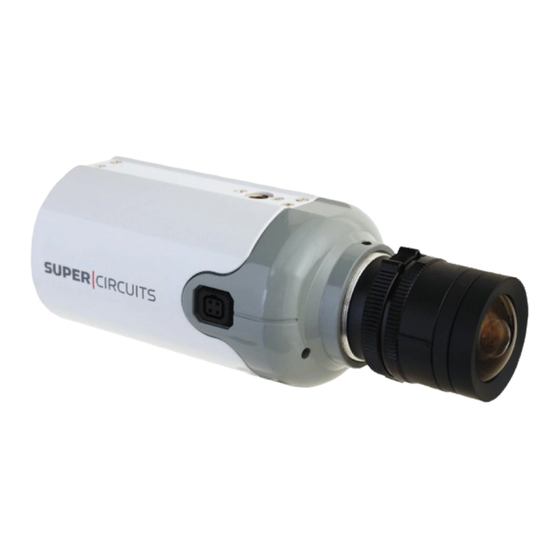
- Page 1 Hi-Resolution Color DVR Box Camera User Manual Products: PC335GDVR Camera With Optional Lens Please read this manual before installing and using this camera and always follow instructions for proper use. Save this manual away for future reference. PC335GDVR_CM...
- Page 2 LEGAL NOTICE Supercircuits products are designed to meet safety and performance standards with the use of specific Supercircuits authorized accessories. Supercircuits disclaims liability associated with the use of non-Supercircuits authorized accessories. The recording, transmission, or broadcast of any person’s voice without their consent or a court order is strictly prohibited by law.
- Page 3 PRECAUTIONS Precautions Do not install the camera in temperature condition or humidity that is • outside the specified operating range. Do not install the camera under unstable lighting. • Do not touch the CCD element. If it is necessary to clean the element, use •...
-
Page 4: Table Of Contents
TABLE OF CONTENTS Table of Contents SECTION 1 Features ..........1 1.1 System options. -
Page 5: Section 1 Features
SECTION 1: FEATURES Features SECTION 1 High resolution 1/3” Sony® CCD image sensor • C/CS lens mount (lens not included) • Digital Noise Reduction (DNR) • Wide Dynamic Range (WDR) • Motion detection • Auto white balance • True Day & Night function •... - Page 6 SECTION 1: FEATURES Auto-Iris Jack Auto-Iris Jack Pin Assignments DC Driver - Control + Control - Drive + Drive www.supercircuits.com...
-
Page 7: Back View
SECTION 1: FEATURES Back View Audio Function setup joystick UTP Gain 12 VDC Video RS485 and UTP terminations SD Card * The camera will accept SD, MMC, and SDHC memory cards up to 32GB. Hi-Resolution Color DVR Box Camera User Manual... -
Page 8: System Options
SECTION 1: FEATURES Remote Control Delete Press to delete the file in the recordings list. ESC / MODE Press to return to the previous menu and quick playback. Left / REW Press to move left in the mask area and 4 levels of fast backward playback. - Page 9 SECTION 1: FEATURES Connect Multiple camera system with DVR and monitor Multiple camera system with DVR and monitor Hi-Resolution Color DVR Box Camera User Manual...
-
Page 10: Section 2 Installation
SECTION 2: INSTALLATION Installation SECTION 2 2.1 What’s in the box The camera package contains: Camera assembly • Hex wrench • Remote control • Instruction manual • 2.2 What you need To install the camera, you will need: C/CS type lens •... - Page 11 SECTION 2: INSTALLATION 1. Using the bracket mounting plate as a template, mark the location of the mounting screw holes on the mounting surface. Camera attachment Mounting screw screw locations Directional adjustment screw Use the mounting bracket to mark holes for mounting screws 2.
- Page 12 SECTION 2: INSTALLATION 7. Attach the camera to the mounting bracket by tightening the camera attachment screw into the mounting bracket connector. 8. Tighten the directional adjustment screw to hold the camera in position. 9. Attach video, audio, and power extension cables to the connectors on the back of the camera.
-
Page 13: Aiming The Camera
SECTION 2: INSTALLATION 2.4 Aiming the Camera 1. While observing video from the camera, hold the camera in place and loosen the directional adjustment screw until the camera can move freely. 2. Point the camera at the center of your surveillance target. Correct the horizontal alignment of the picture, and then tighten directional adjustment screw. -
Page 14: Section 3 Setup Menu (Osd) Usage
SECTION 3: SETUP MENU USAGE SETUP Menu (OSD) Usage SECTION 3 The SETUP menu can be accessed and configured using the function setup joystick on the back of the camera, or through an RS-485 interface. It appears as an OSD over the video image from the camera. -
Page 15: Setup Menu Options
SECTION 3: SETUP MENU USAGE To access the SETUP menu: 1. Connect a video monitor to the video connector on the back of the camera. 2. While observing video from the camera, press the joystick in (toward the camera backplate) to open the SETUP menu. 3. - Page 16 SECTION 3: SETUP MENU USAGE EXPOSURE SHUTTER: Select either auto or manual shutter. • AUTO: Select for auto shutter. Default: 1/60 sec — FLK: Select for Flicker shutter. Select from 1/250 ~ 1/100000 sec shutter time. — BRIGHTNESS: Adjust as needed. Range: 0 ~ 255 steps. •...
- Page 17 SECTION 3: SETUP MENU USAGE AWC g SET: To find the optimal setting for the current luminance environment in • this mode, point the camera towards a sheet of white paper then press SET. NOTE When the environment changes, repeat this procedure. MANUAL: Select this mode to manually set the white balance.
- Page 18 SECTION 3: SETUP MENU USAGE BACKLIGHT OFF: Deactivate the BACKLIGHT Function. • BLC: Enable to select an area of a picture to view more clearly. • AREA SEL: AREA 1 / AREA 2 — AREA STATE: ON /OFF — GAIN: Adjust the value between. Range: 0 ~ 255 steps —...
- Page 19 SECTION 3: SETUP MENU USAGE DAY / NIGHT AUTO: This mode is set for color in a normal environment, but switches to B / W • mode when ambient illumination is low. To set up the switching time or speed for AUTO mode.
- Page 20 SECTION 3: SETUP MENU USAGE - When using a video auto-iris lens, automatic switching between Color and B/W may not occur if the level is set too low. NOTE - The AGC in the EXPOSURE menu is “OFF” when DAY / NIGHT menu is “AUTO”. - If using IR illumination, install an Extra-low Dispersion Lens to improve camera focus.
- Page 21 SECTION 3: SETUP MENU USAGE If you move the cursor to CLR and press SET, all the letters are deleted. To edit a single letter, move the cursor to the joystick left arrow, then press SET. Move the cursor to the NOTE letter being removed, then press SET.
- Page 22 SECTION 3: SETUP MENU USAGE PARK. LINE: The Park Line feature can be useful when the camera is installed in • vehicles as a backup camera. Adjust as necessary. Parameters set the position of the parking lines. See the diagram to the right. LT: 0 ~ 194 —...
- Page 23 SECTION 3: SETUP MENU USAGE NEG. IMAGE: ON / OFF. Set a negative image effect. • NOTE In the LENS SHAD menu, IR models provide only the OFF option. COMM ADJ (communication adjustment): Use function to set up the communication •...
-
Page 24: Section 4 Dvr Usage
SECTION 4: DVR USAGE DVR Usage SECTION 4 The remote control provided with your camera is used to control embedded DVR. The DVR control interface appears as an OSD with a SET UP menu that includes: Image Setting • Record Setting •... -
Page 25: Initial Dvr Setup For Recording
SECTION 4: DVR USAGE 4.1 Initial DVR setup for recording To setup and your camera DVR for recording video, configure the system settings, image settings, record settings and then choose a record mode. System Setting 1. Insert an SD, MMC, or SDHC card (up to 32GB) into the card slot on the back of the camera. -
Page 26: Image Setting
SECTION 4: DVR USAGE 7. To format your memory card, use the UP or DOWN button to highlight Format, then press ENTER. Press the UP button to select YES, then press ENTER again. Allow the format operation to complete before continuing. Image Setting 1. - Page 27 SECTION 4: DVR USAGE start time is displayed at the top in the format YYYY/MM/DD HH:MM, and the end time is displayed below. Use the UP and DOWN buttons to change the value of the year, if necessary, the press the Right button to move to the next field. Adjust the value of each field until the desired start time and end time is displayed, then press ENTER to confirm the setting and return to the REC.
- Page 28 SECTION 4: DVR USAGE the image where motion should be sensed. When finished, press ESC to return to the Motion Detection screen. b. In the Motion Detection screen, press DOWN to highlight Sensitivity, then press ENTER. In the Sensitivity submenu, select H (high), M (medium), or L (low), then press ENTER to return to close the submenu.
-
Page 29: Playing Back Recorded Video
SECTION 4: DVR USAGE 4.2 Playing back recorded video Video recorded by your camera can be played back either by the camera or by an external device such as a computer. Playback with the camera 1. From the live camera view screen, press the MENU button to open the SET UP menu. 2. - Page 30 SECTION 4: DVR USAGE 3. In the file list screen, use the UP and DOWN buttons to select a file to play, press ENTER to confirm your selection, then press PLAY to watch the file. You can control playback as follows: Press the Left/REW button to rewind the file.
-
Page 31: Section 5 Cleaning
SECTION 5: CLEANING Cleaning SECTION 5 Clean the camera lens and IR lamp shield with an approved glass cleaning solution and a lint free cloth. Remove all foreign particles, such as plastic or rubber materials, attached to the • camera housing. These may cause damage to the surface over time. Dust can be removed from the unit by wiping it with a soft damp cloth. -
Page 32: Section 6 Specifications
SECTION 6: SPECIFICATIONS Specifications SECTION 6 Model PC335GDVR Image Sensor 1/3” Sony® CCD and Nextchip DSP Total Pixels 768(H) x 494(V) Resolution Color: 600 TV Lines; B/W: 700 TV Lines S/N (Y Signal) ≥ 52dB (AGC OFF, Weight ON) Min Illumination 0.1 LUX F 1.2... - Page 33 SECTION 6: SPECIFICATIONS Model PC335GDVR Power Supply 12 VDC Power Consumption 400mA (max) @ DC12V Operating Temperature 14°F ~ 113°F (-10°C ~ 45°C) Storage Temperature 44°F ~ 140°F (-20°C ~ 60°C) Dimensions (L x W x H) 4.43” x 2.04” x 2.38” (112.5mm x 60.33mm x 51.93mm) Weight 7.05 oz ±...
-
Page 34: Appendix A Troubleshooting
APPENDIX A: TROUBLESHOOTING Troubleshooting APPENDIX A Before sending the camera for repair, please follow the suggestions listed below and make sure that the camera is installed correctly. If it still does not perform adequately, please consult your supplier or contact Supercircuits Support at 1.800.335.9777. 1. - Page 35 APPENDIX A: TROUBLESHOOTING c. The video cables are not connected properly. This camera is a precision instrument and when treated with care, will provide years of satisfactory performance. If a problem does occur, do not open the camera to make repairs. Servicing should always be referred to CAUTION your supplier.
-
Page 36: Appendix B Dimensions
APPENDIX B: DIMENSIONS Dimensions APPENDIX B 4.43” 2.38” 2.04” www.supercircuits.com...
Need help?
Do you have a question about the PC335GDVR and is the answer not in the manual?
Questions and answers