Table of Contents
Advertisement
Quick Links
Advertisement
Table of Contents

Related Manuals for VIA Technologies EPIA-NL


Summary of Contents for VIA Technologies EPIA-NL
- Page 1 User’s Manual EPIA-NL Version 1.11 September 23, 2008...
- Page 2 However, VIA Technologies assumes no responsibility for the use or misuse of the information in this document and for any patent infringements that may arise from the use of this document.
- Page 3 FCC-B Radio Frequency Interference Statement This equipment has been tested and found to comply with the limits for a class B digital device, pursuant to part 15 of the FCC rules. These limits are designed to provide reasonable protection against harmful interference when the equipment is operated in a commercial environment.
-
Page 4: Safety Instructions
Safety Instructions Always read the safety instructions carefully. Keep this User's Manual for future reference. Keep this equipment away from humidity. Lay this equipment on a reliable flat surface before setting it up. The openings on the enclosure are for air convection hence protects the equipment from overheating. - Page 5 ONTENTS One VIA Nano-ITX mainboard One Quick Installation Guide One ATA-66/100/133 IDE ribbon cable One USB 2.0 4-port cable One PS2 cable for KB/MS One ATX power cable adapter One driver and utilities CD One 100/10 LAN cable One VGA cable...
-
Page 6: Table Of Contents
ABLE OF ONTENTS Box Contents ..................i Table of Contents................ii Specifications ..................1 Mainboard Specifications ..............2 Mainboard Layout ................4 Slots....................5 Onboard Connectors............... 5 Onboard Jumpers................5 Installation ..................6 CPU....................7 Memory Module Installation ............9 Connecting the Power Supply ............10 Connectors ...................11 Jumpers ..................19 Slots.....................20... - Page 7 PNP/PCI Configurations ..............49 IRQ Resources ................51 PC Health Status ................52 Frequency/Voltage Control ............53 Load Fail-Safe Defaults..............56 Load Optimized Defaults..............57 Set Supervisor/User Password............58 Save & Exit Setup .................59 Exit Without Saving ...............60 Driver Installation ................61 Driver Utilities ................62 CD Content ...................64 Smart 5.1 ..................65 Enabling Smart 5.1................66...
- Page 8 This page left intentionally blank.
-
Page 9: Specifications
HAPTER Specifications The ultra-compact and highly integrated VIA EPIA-NL Nano-ITX mainboard is the smallest form-factor available today. Through a high level of integration, the Nano-ITX measures at only 50% of the size of a Mini-ITX mainboard. The mainboard comes with an embedded VIA Luke CoreFusion™... -
Page 10: Mainboard Specifications
Chapter 1 AINBOARD PECIFICATIONS • VIA Luke CoreFusion™ Processor South Bridge • VIA VT8237R-series South Bridge Graphics • Integrated UniChrome™ Pro AGP • MPEG-2 decoding and MPEG-4 acceleration Audio • VIA VT1617A 6-channel AC'97 codec Memory • 1 x DDR 266/333/400 SODIMM socket (up to 1 GB) Expansion Slot •... - Page 11 Specifications Onboard I/O Connectors • 1 x USB pin header for 8 additional USB 2.0/1.1 ports • 1 x SIO pin header (including COM port, SIR and LPC support) • 1 x KB/MS pin header (switchable for KB/MS connector) • 2 x Fan connectors (CPU Fan and System Fan) •...
-
Page 12: Mainboard Layout
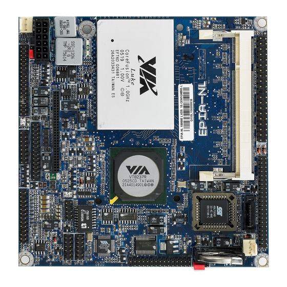
Chapter 1 AINBOARD AYOUT SODIMM IDE1 JCRT_ CAPTURE LUKE CoreFusion Processor JLVDS/DVI JUSB IDE2 VT8237R-series JAUDIO South Bridge SATA JKBMS BIOS Socket JFPANL JSIO CMOS Battery JLAN Mini-PCI on Bottom-side of Board CLEAR_CMOS SYS FAN... -
Page 13: Slots
Specifications LOTS Port Description Page Mini PCI Expansion card slot SODIMM Memory module slot NBOARD ONNECTORS Connector Description Page Audio Audio Jacks connector (Line-In, Line-Out, Microphone) / CD-In / SPDIF CPU FAN CPU fan connector VGA port / SMBUS / CAP0 connector F_PANEL Case connectors IDE 1-2... -
Page 14: Installation
HAPTER Installation This chapter provides you with information about hardware installation procedures. It is recommended to use a grounded wrist strap before handling computer components. Static electricity may damage some components. -
Page 15: Cpu
Installation The VIA EPIA-NL Nano-ITX mainboard includes an embedded VIA Luke CoreFusion™ Processor. The VIA Luke CoreFusion™ Processor provides ultra- low power consumption and advanced thermal dissipation properties and features a fanless design. The VIA Luke CoreFusion™ Processor requires only... - Page 16 Chapter 2 CPU Fan and System Fan: CPUFAN and SYSFAN The CPUFAN (CPU fan) and SYSFAN (system fan) run on +12V and maintain system cooling. When connecting the wire to the connectors, always be aware that the red wire is the Positive and should be connected to the +12V. The black wire is Ground and should always be connected to GND.
-
Page 17: Memory Module Installation
Installation EMORY ODULE NSTALLATION The VIA EPIA-NL Nano-ITX mainboard provides one 200-pin SODIMM slot for DDR266/333/400 SDRAM memory modules. DDR SDRAM Module Installation Procedures • Make sure the notch is on the proper side. • Insert the memory module into the slot at a 30 degree angle (30 degrees from the board). -
Page 18: Connecting The Power Supply
ONNECTING THE OWER UPPLY The VIA EPIA-NL Nano-ITX mainboard requires a special power cable adapter to connect to a conventional ATX power supply. Before inserting the power supply connector, always make sure that all components are installed correctly to ensure that no damage will be caused. -
Page 19: Connectors
Installation ONNECTORS Hard Disk Connectors: IDE1 & IDE2 The mainboard has a 32-bit Enhanced IDE and Ultra DMA 66/100/133 controller that provides PIO mode 0~4, Bus Master, and Ultra DMA 66/100/133 functions. Up to four IDE devices can be connected to the system. - Page 20 Chapter 2 Audio Jacks Connector: JAUDIO This pin header is for the CDROM, SPDIF and Audio connector. The Line-Out jack signals are for connecting to external speakers or headphones. The Line-In jack signals are for connecting to an external audio device such as a CD player, tape player, etc.
- Page 21 Installation CRT Connector: JCRT_CAPTURE This pin header can be used to attach additional port for VGA monitor, SMBUS and CAP0. JCRT_CAPTURE Signal Signal AR_IN DDC_DA AG_IN DDC_CK AB_IN HSYNC_IN VSYNC_IN CPA1D1 CAP1CLK CPA1D3 CPA1D0 CPA1D4 CPA1D2 CPA1D5 CPA1D6 CPA1D7 SMBDT SMBCK +3.3V...
- Page 22 Chapter 2 Case Connectors: FPNL The F_PANEL pin header block allows you to connect to the power switch, reset switch, power LED, HDD LED and the case speaker. FPNL Signal Signal +5V Dual +5V Dual HD_LED -PLED PW_BN Reset_SW SPEAKER Power Switch (PW_BN) Connect to a 2-pin push button switch.
- Page 23 Installation KBMS Connector: JKBMS The mainboard provides a PS2 header to attach a PS2 keyboard and mouse. JKBMS Signal Signal +5V Dual +5V Dual Keyboard_DATA Mouse_DATA Keyboard_CLK Mouse_CLK USB Connector: JUSB This pin header is used to connect up to 8-port USB2.0/1.1 cable. JUSB Signal Signal...
- Page 24 Chapter 2 LPC / SIR Connector: JSIO This pin header is for LPC / SIR / COM1 devices. JSIO Signal Signal LAD1 LPCCLK1 -PCIRSTX LAD0 SIO_OSC LAD2 -LFRAME SERIRQ LAD3 -LDRQ1 -EXTSMI +3.3V +3.3V IRTX IRRX DCD1 -SIN1 -SOUT1 DTR1 RTS1 DSR1 -XRI1...
- Page 25 Installation LVDS / DVI Connector: JLVDS/DVI This connector works as the interface to multiple display devices. An additional daughter card is required for LVDS or DVI supports respectively. The LVDS daughter card, LVDS-07, is currently available. Signal Signal JLVDS/DVI +12V +12V +3.3V ENPVEE...
- Page 26 Chapter 2 LAN Connector: JLAN This pin header allows you to connect a network card with the LAN function. JLAN Signal Signal +3.3VLANPH -LAN_SP100 P4/P5 P7/P8 -LAN_ACT TV Out Connector: JTV This pin header allows you to use different types of TV signal interfaces, including S-Video, RCA and Component (YPbPr / Scart / D-Terminal) outputs.
-
Page 27: Jumpers
Installation UMPERS The mainboard provides jumpers for setting some mainboard functions. This section will explain how to change the settings of the mainboard functions using the jumpers. Clear CMOS: CLEAR_CMOS The onboard CMOS RAM stores system configuration data and has an onboard battery power supply. -
Page 28: Slots
Chapter 2 LOTS Peripheral Component Interconnect: Mini PCI The Mini PCI slot allows you to insert Mini PCI expansion cards. When adding or removing expansion cards, first unplug the power supply. Read the documentation for the expansion card if any changes to the system are necessary. -
Page 29: Bios Setup
HAPTER BIOS Setup This chapter gives a detailed explanation of the BIOS setup functions. -
Page 30: Entering Setup
Chapter 3 NTERING ETUP Power on the computer and press <Delete> during the beginning of the boot sequence to enter the BIOS setup menu. If you missed the BIOS setup entry point, you may restart the system and try again. -
Page 31: Control Keys
BIOS Setup ONTROL Keys Description Up Arrow Move to the previous item Down Arrow Move to the next item Left Arrow Move to the item in the left side Right Arrow Move to the item in the right side Enter Select the item Escape Jumps to the Exit menu or returns to the main menu from a... -
Page 32: Navigating The Bios Menus
Chapter 3 BIOS M AVIGATING THE ENUS The main menu displays all the BIOS setup categories. Use the control keys Up/Down arrow keys to select any item/sub-menu. Description of the selected/highlighted category is displayed at the bottom of the screen. An arrow symbol next to a field indicates that a sub-menu is available (see figure below). -
Page 33: Getting Help
BIOS Setup ETTING The BIOS setup program provides a “General Help” screen. You can display this screen from any menu/sub-menu by pressing <F1>. The help screen displays the keys for using and navigating the BIOS setup. Press <Esc> to exit the help screen. -
Page 34: Main Menu
Chapter 3 Phoenix - AwardBIOS CMOS Setup Utility Standard CMOS Features Frequency / Voltage Control Advanced BIOS Features Load Fail-Safe Defaults Advanced Chipset Features Load Optimized Defaults Integrated Peripherals Set Supervisor Password Power Management Setup Set User Password PnP / PCI Configurations Save &... - Page 35 BIOS Setup Load Fail-Safe Defaults Use this menu option to load the BIOS default settings for minimal and stable system operations. Load Optimized Defaults Use this menu option to load BIOS default settings for optimal and high performance system operations. Set Supervisor Password Use this menu option to set the BIOS supervisor password.
-
Page 36: Standard Cmos Features
Chapter 3 CMOS F TANDARD EATURES Phoenix - AwardBIOS CMOS Setup Utility Standard CMOS Features Date (mm:dd:yy) Tue, Jan 7 2003 Item Help Time (hh:mm:ss) 20 : 21 : 31 Menu Level IDE Channel 0 Master [None] Change the day, month, year IDE Channel 0 Slave [QUANTUM FIREBALLP AS] and century... -
Page 37: Ide Drives
BIOS Setup IDE D RIVES Phoenix - AwardBIOS CMOS Setup Utility IDE Channel 0 Master IDE HDD Auto-Detection [Press Enter] Item Help Menu Level IDE Channel 0 Master [Auto] Access Mode [Auto] To auto-detect the HDD's size, head... channel Capacity 0 MB Cylinder Head... -
Page 38: Advanced Bios Features
Chapter 3 BIOS F DVANCED EATURES Phoenix - AwardBIOS CMOS Setup Utility Advanced BIOS Features Hard Disk Boot Priority [Press Enter] Item Help Virus Warning [Disabled] Menu Level CPU Internal Cache [Enabled] Quick Power On Self Test [Enabled] Select Hard Disk Boot Priority First Boot Device [USB-FDD] Second Boot Device... - Page 39 BIOS Setup First/Second/Third Boot Device Set the boot device sequence as BIOS attempts to load the disk operating system. Setting Description LS120 Boot from LS-120 drive Hard Disk Boot from the HDD CD-ROM Boot from CD-ROM ZIP100 Boot from ATAPI ZIP drive USB-FDD Boot from USB floppy drive USB-ZIP...
- Page 40 Chapter 3 Typematic Delay (Msec) This item sets the delay between when the key was first pressed and when the system begins to repeat the signal from the depressed key. Settings: [250, 500, 750, 1000] Security Option Selects whether the password is required every time the System boots, or only when you enter Setup.
-
Page 41: Hard Disk Boot Priority
BIOS Setup RIORITY Phoenix - AwardBIOS CMOS Setup Utility Hard Disk Boot Priority 1. Bootable Add-in Cards Item Help Menu Level Use < > or < > to Select a device then press < + > to move it up, or < - > to move it down the list. -
Page 42: Advanced Chipset Features
Chapter 3 DVANCED HIPSET EATURES Phoenix - AwardBIOS CMOS Setup Utility Advanced Chipset Features Display Card Priority [PCI Slot] Item Help AGP & P2P Bridge Control [Press Enter] Menu Level CPU & PCI Bus Control [Press Enter] Select Display Device [CRT] If there are display cards on Panel Type... - Page 43 BIOS Setup 800x480:1:On, 1024x768:2:On, 1024x768:1:Off, 1280x768:2:Off, 1280x768:1:Off, 1280x1024:2:Off, 1400x1050:2:Off, 1600x1200:2:Off]...
- Page 44 Chapter 3 TV H/W Layout Settings: [Default, COMPOSITE + S-Video, COMP. + R/G/B, COMP. + Y/Cb/Cr, COMP. + SDTV-R.G.B, COMP. + SDTV-Y.Pb.Pr, COMPOSITE, S-Video, R.G.B, Y.Cb.Cr, SDTV – R.G.B, SDTV – Y.Pb.Pr, S-Video + R.G.B, S-Video + Y.b.Cr] TV Type This setting refers to the native resolution of the display being used with the system.
-
Page 45: Agp & P2P Bridge Control
BIOS Setup AGP & P2P B RIDGE ONTROL Phoenix - AwardBIOS CMOS Setup Utility AGP & P2P Bridge Control AGP Aperture Size [128] Item Help AGP 3.0 Mode Menu Level VGA Share Memory Size [64] Direct Frame Buffer Size [Enabled] : Move Enter: Select +/-/PU/PD: Value... -
Page 46: Cpu & Pci Bus Control
Chapter 3 CPU & PCI B ONTROL Phoenix - AwardBIOS CMOS Setup Utility CPU & PCI Bus Control VLink mode selection [Mode 1] Item Help Menu Level : Move Enter: Select +/-/PU/PD: Value F10: Save ESC: Exit F1: General Help F5: Previous Values F6: Fail-Safe Defaults F7: Optimized Defaults... -
Page 47: Tv Output Connector
BIOS Setup TV O UTPUT ONNECTOR Phoenix - AwardBIOS CMOS Setup Utility TV Output Connector CVBS (Composite) [Enabled] Item Help S-Video 0 (Y/C) [Enabled] Menu Level R/G/B [Disabled] Cr/Y/Cb [Disabled] SDTV-R/G/B [Disabled] SDTV-Pr/Y/Pb [Disabled] : Move Enter: Select +/-/PU/PD: Value F10: Save ESC: Exit F1: General... -
Page 48: Integrated Peripherals
Chapter 3 NTEGRATED ERIPHERALS Phoenix - AwardBIOS CMOS Setup Utility Integrated Peripherals SuperIO Device [Press Enter] Item Help Menu Level Onboard IDE Channel 1 [Enabled] Onboard IDE Channel 2 [Enabled] IDE Prefetch Mode [Enabled] OnChip SATA [Enabled] SATA Mode [RAID] AC97 Audio [Auto] VIA OnChip LAN... - Page 49 BIOS Setup AC’97 Audio Auto allows the mainboard to detect whether an audio device is used. If the device is detected, the onboard VIA AC'97 (Audio Codec'97) controller will be enabled; otherwise, it is disabled. Disable the controller if another controller card is being used to connect to an audio device.
-
Page 50: Super Io Device
Chapter 3 IO D UPER EVICE Phoenix - AwardBIOS CMOS Setup Utility SuperIO Device Onboard Serial Port 1 [3F8/IRQ4] Item Help Onboard Serial Port 2 [Disabled] Menu Level UART Mode Select IrDA RxD, TxD Active [Hi, Hi] IR Transmission Delay [Disabled] UR2 Duplex Mode [Half]... -
Page 51: Power Management Setup
BIOS Setup OWER ANAGEMENT ETUP Phoenix - AwardBIOS CMOS Setup Utility Power Management Setup ACPI Suspend Type [S1(POS)] Item Help HDD Power Down [Disable] Menu Level Power Management Timer [Disable] Video Off Option [Suspend -> Off] This item allows you to select how the BIOS put the system Power Off by PWRBTN [Instant-Off]... - Page 52 Chapter 3 Video Off Option Select whether or not to turn off the screen when system enters power saving mode, ACPI OS such as Windows XP will override this option. Setting Description Always On Screen is always on even when system enters power saving mode Suspend ->...
-
Page 53: Peripheral Activities
BIOS Setup ERIPHERAL CTIVITIES Phoenix - AwardBIOS CMOS Setup Utility Peripherals Activities VGA Event [OFF] Item Help COM Event [COM] Menu Level HDD Event [ON] PCI Master Event [OFF] Decide whether or not the power management unit PS2KB Wakeup Select [Hot Key] PS2MS Wakeup from S3/S4/S5 [Disabled]... - Page 54 Chapter 3 PS2KB Wakeup Select When selecting “Password”, press <Page Up> or <Page Down> to change password. The maximum number of characters is eight. “PS2MS Wakeup from S3/S4/S5” and “PS2KB Wakeup from S3/S4/S5” will be disabled while changing the password. Settings: [Hot Key, Password] PS2MS Wakeup from S3/S4/S5 Enables any mouse activity to restore the system from the power saving...
- Page 55 BIOS Setup RTC Alarm Resume Sets a scheduled time and/or date to automatically power on the system. Settings: [Disabled, Enabled] Date (of Month) The field specifies the date for “RTC Alarm Resume”. Resume Time (hh:mm:ss) The field specifies the time for “RTC Alarm Resume”.
-
Page 56: Irqs Activities
Chapter 3 CTIVITIES Phoenix - AwardBIOS CMOS Setup Utility IRQs Activities Primary INTR [ON] Item Help IRQ3 (Reserved) [Disabled] Menu Level IRQ4 (COM 1) [Enabled] IRQ5 (Reserved) [Disabled] If you choose Disabled, the IRQ6 (Floppy Disk) [Enabled] power management unit will IRQ7 (Reserved) [Disabled] IRQ8 (RTC Alarm) -
Page 57: Pnp/Pci Configurations
BIOS Setup PNP/PCI C ONFIGURATIONS Phoenix - AwardBIOS CMOS Setup Utility PnP / PCI Configurations PNP OS Installed [No] Item Help Reset Configuration Data [Disabled] Menu Level Resources Controlled by [Auto(ESCD)] Select Yes if you are using a IRQ Resources Press Enter Plug and Play capable Assign IRQ for VGA... - Page 58 Chapter 3 Resource Controlled By Enables the BIOS to automatically configure all the Plug-and-Play compatible devices. When set to “Auto(ESCD)”, the BIOS will automatically assign IRQ, DMA and memory base address fields. When set to “Manual”, all of the “IRQ Resources”...
-
Page 59: Irq Resources
BIOS Setup IRQ R ESOURCES Phoenix - AwardBIOS CMOS Setup Utility IRQ Resources IRQ-3 assigned to [PCI Device] Item Help IRQ-4 assigned to [PCI Device] Menu Level IRQ-5 assigned to [PCI Device] IRQ-7 assigned to [PCI Device] Legacy ISA for devices IRQ-9 assigned to [PCI Device] compliant with the original PC... -
Page 60: Pc Health Status
Chapter 3 PC H EALTH TATUS Phoenix - AwardBIOS CMOS Setup Utility PC Health Status Item Help Menu Level CPU FAN Speed Vcore (V) 3.3Vin (V) + 5V +12V VBAT (V) 5VSB (V) : Move Enter: Select +/-/PU/PD: Value F10: Save ESC: Exit F1: General Help... -
Page 61: Frequency/Voltage Control
BIOS Setup REQUENCY OLTAGE ONTROL Phoenix - AwardBIOS CMOS Setup Utility Frequency / Voltage Control DRAM Clock [By SPD] Item Help DRAM Timing [Auto By SPD] Menu Level SDRAM CAS Latency Bank Interleave Disabled Precharge to Active(Trp) Active to Precharge(Tras) Active to CMD(Trcd) REF to ACT/REF to REF(Trfc) ACT(0) to ACT(1) (TRRD) - Page 62 Chapter 3 Bank Interleave This item is for setting the interleave mode of the SDRAM interface. Interleaving allows banks of SDRAM to alternate their refresh and access cycles. One bank will undergo its refresh cycle while another is being accessed. This improves performance of the SDRAM by masking the refresh time of each bank.
- Page 63 BIOS Setup DRAM Command Rate This field is for setting how fast the memory controller sends out commands. Lower setting equals faster command rate. Note: Some memory modules may not be able to handle lower settings. Settings: [2T Command, 1T Command] Spread Spectrum Range Settings: [+/-0.1%, +/-0.2%, +/-0.3%, +/-0.6%] Spread Spectrum...
-
Page 64: Load Fail-Safe Defaults
Chapter 3 EFAULTS Phoenix - AwardBIOS CMOS Setup Utility Standard CMOS Features Frequency / Voltage Control Advanced BIOS Features Load Fail-Safe Defaults Advanced Chipset Features Load Optimized Defaults Integrated Peripherals Set Supervisor Password Power Management Setup Set User Password PnP / PCI Configurations Load Fail-Safe Defaults (Y/N)? Save &... -
Page 65: Load Optimized Defaults
BIOS Setup PTIMIZED EFAULTS Phoenix - AwardBIOS CMOS Setup Utility Standard CMOS Features Frequency / Voltage Control Advanced BIOS Features Load Fail-Safe Defaults Advanced Chipset Features Load Optimized Defaults Integrated Peripherals Set Supervisor Password Power Management Setup Set User Password PnP / PCI Configurations Load Optimized Defaults (Y/N)? Save &... -
Page 66: Set Supervisor/User Password
Chapter 3 UPERVISOR ASSWORD Phoenix - AwardBIOS CMOS Setup Utility Standard CMOS Features Frequency / Voltage Control Advanced BIOS Features Load Fail-Safe Defaults Advanced Chipset Features Load Optimized Defaults Integrated Peripherals Set Supervisor Password Power Management Setup Set User Password PnP / PCI Configurations Enter Password: Save &... -
Page 67: Save & Exit Setup
BIOS Setup & E ETUP Phoenix - AwardBIOS CMOS Setup Utility Standard CMOS Features Frequency / Voltage Control Advanced BIOS Features Load Fail-Safe Defaults Advanced Chipset Features Load Optimized Defaults Integrated Peripherals Set Supervisor Password Power Management Setup Set User Password PnP / PCI Configurations SAVE to CMOS &... -
Page 68: Exit Without Saving
Chapter 3 ITHOUT AVING Phoenix - AwardBIOS CMOS Setup Utility Standard CMOS Features Frequency / Voltage Control Advanced BIOS Features Load Fail-Safe Defaults Advanced Chipset Features Load Optimized Defaults Integrated Peripherals Set Supervisor Password Power Management Setup Set User Password PnP / PCI Configurations Quit Without Saving (Y/N)? Save &... -
Page 69: Driver Installation
HAPTER Driver Installation This chapter gives you brief descriptions of each mainboard driver and application. You must install the VIA chipset drivers first before installing other drivers such as audio or VGA drivers. The applications will only function correctly if the necessary drivers are already installed. -
Page 70: Driver Utilities
Chapter 4 RIVER TILITIES Getting Started The mainboard includes a Driver Utilities CD that contains the driver utilities and software for enhancing the performance of the mainboard. If the CD is missing from the retail box, please contact the local dealer for the CD. Note: The driver utilities and software are updated from time to time. - Page 71 Driver Installation Running the Driver Utilities CD To start using the CD, insert the CD into the CD-ROM or DVD-ROM drive. The CD should run automatically after closing the CD-ROM or DVD-ROM drive. The driver utilities and software menu screen should then appear on the screen.
-
Page 72: Cd Content
Chapter 4 CD C ONTENT VIA 4in1 Drivers: Contains VIA ATAPI Vendor Support Driver (enables the performance enhancing bus mastering functions on ATA-capable Hard Disk Drives and ensures IDE device compatibility), AGP VxD Driver (provides service routines to your VGA driver and interface directly to hardware, providing fast graphical access), IRQ Routing Miniport Driver (sets the system's PCI IRQ routing sequence) and VIA INF Driver (enables the VIA Power Management function). -
Page 73: Smart 5.1
PPENDIX Smart 5.1 This chapter gives you brief description of how Smart 5.1 is enabled if your board is equipped with the VT1617A 6-channel AC'97 codec. -
Page 74: Enabling Smart 5.1
Appendix A NABLING MART Smart5.1 allows the system to output 6-channel audio directly from the audio jacks on the mainboard, using the traditional line-in, line-out and microphone jacks as output jacks. Windows® XP/2000 supports 6-channel. Windows® 98 only supports 4-channel. The examples in this section are based on Windows®... - Page 75 Smart 5.1 Example A 1. Double-click “Sounds and Audio Devices” icon in the control panel. 2. Select the “Audio” tab. Then press “Advanced” as shown in the picture.
- Page 76 Appendix A 3. Choose “5.1 surround sound speakers” to support the 6-channel function.
- Page 77 Smart 5.1 Example B 1. Double-click “Sounds and Audio Devices” icon in the control panel and then select the “Audio” tab on the panel as shown below. Press the “Volume” button in the “Sound playback” area 2. Select “Options” from the “Front Speaker” panel and select the item “Advanced Controls”.
- Page 78 Appendix A 3. Click on the “Advanced” button. 4. Check the “Smart5.1 Enable” item as shown in the panel below.
- Page 79 Smart 5.1 After completing the previous settings, connect the speakers to the 3-jack connectors. Shown below are the corresponding connections to setup the 6-channel system. Jack 2-channel 6-channel Line-out Line-out Front (Left/Right) Line-in Line-in Rear (Left/Right) Microphone Microphone Center/Sub-woofer...
Need help?
Do you have a question about the EPIA-NL and is the answer not in the manual?
Questions and answers