Table of Contents
Advertisement
This chapter describes the ServerIron 4G Series.
Overview
The ServerIron 4G Series includes three stackable switches: ServerIron 4G, ServerIron 4G-SSL, and FIPs 140-2
level 2 certified ServerIron 4G-SSL-FIPS.
NOTE: ServerIron 4G-SSL-FIPS requires software release 10.2.01 or later.
Targeting small and mid-sized enterprise, eCommerce, and service provider sites, ServerIron 4G Series highlights
include:
•
ASIC-Based Application Processors
•
Choice of non-SSL and SSL-Integrated switches
•
Hardware SSL Acceleration (ServerIron 4G-SSL and 4G-SSL-FIPS)
•
FIPS 140-2 level 2 certification (ServerIron 4G-SSL-FIPS only)
NOTE: The fundamental difference between the SSL and non-SSL ServerIron switches is internal. There is an
embedded hardware ASIC for SSL acceleration in the ServerIron 4G-SSL and 4G-SSL-FIPS switches.
Figure 4.1 on page 4-1 shows the ServerIron 4G.
Figure 4.1 ServerIron 4G
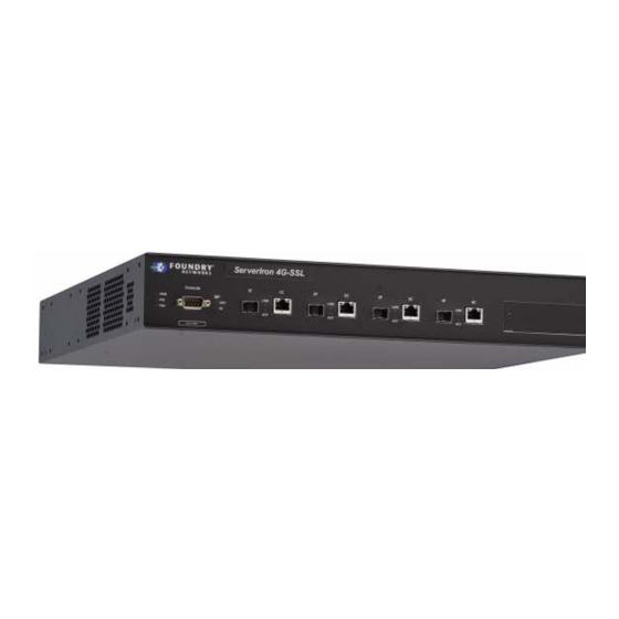
Figure 4.2 shows the ServerIron 4G-SSL.
October 2008
© 2008 Foundry Networks, Inc.
Chapter 4
ServerIron 4G Series
4 - 1
Advertisement
Table of Contents

Related Manuals for Foundry Networks ServerIron 4G-SSL


Summary of Contents for Foundry Networks ServerIron 4G-SSL
- Page 1 ServerIron 4G Series This chapter describes the ServerIron 4G Series. Overview The ServerIron 4G Series includes three stackable switches: ServerIron 4G, ServerIron 4G-SSL, and FIPs 140-2 level 2 certified ServerIron 4G-SSL-FIPS. NOTE: ServerIron 4G-SSL-FIPS requires software release 10.2.01 or later.
-
Page 2: Common Features
Front Panel Figure 4.4 on page 4-3 shows the ServerIron 4G Series front panel. NOTE: The ServerIron 4G-SSL front panel shown below is identical to the ServerIron 4G front panel. Only the name (4G-SSL) on the front panel is different. - Page 3 • Indicates BP is receiving packets. • OFF Indicates BP is not receiving packets. Fiber Ports (4 Sets) Link Green • Indicates port connectivity. • OFF Indicates no port connectivity. October 2008 © 2008 Foundry Networks, Inc. 4 - 3...
- Page 4 The supported power supplies can be swapped in or out of the device while the device is running. You can remove and insert a power supply without opening the chassis. If the device contains redundant power supplies, 4 - 4 © 2008 Foundry Networks, Inc. October 2008...
-
Page 5: Site Preparation
The ServerIron 4G Series systems ship with the following items. Review the list below and verify the contents. If any items are missing, contact the place of purchase. • Foundry Networks ServerIron 4G or ServerIron 4G-SSL device • 115V AC power cable (for AC sourced devices) October 2008 ©... -
Page 6: General Requirements
• A straight-through EIA/TIA DB-9 serial cable (F/F). You can separately order the serial cable from Foundry Networks. If you prefer to build your own cable, see the pinout information in “Attaching a PC or Terminal” on page 4-12. You can use the serial connection to perform basic configuration tasks such as assigning an IP address and network mask to the system. - Page 7 The minimum current draw for the system is one AC power supply. WARNING: Power supplies are hot swappable. However, Foundry Networks recommends that you disconnect the power supply from AC power before installing or removing the supply. The device can be running while a power supply is being installed or removed, but the power supply itself should not be connected to a power source.
-
Page 8: Installing A Redundant Power Supply
Installing a DC Power Supply Use the following procedures for DC power supplies in ServerIron 4G devices. WARNING: Before beginning the installation, see the precautions in “Power Precautions” on page 4-7. 4 - 8 © 2008 Foundry Networks, Inc. October 2008... - Page 9 Set the device on a flat desktop, table, or shelf. Make sure that adequate ventilation is provided for the system. A 3-inch clearance is recommended on each side. Go to “Powering On the System” on page 4-10. October 2008 © 2008 Foundry Networks, Inc. 4 - 9...
-
Page 10: Powering On The System
Insert the power cable plug into a 115V/120V outlet. NOTE: To turn the system off, simply unplug the power cord(s). NOTE: The socket should be installed near the equipment and should be easily accessible. 4 - 10 © 2008 Foundry Networks, Inc. October 2008... -
Page 11: Verifying Proper Operation
Power supply 1 is located in the right-hand bay (when you are facing the rear of the device). Power supply 1 is not installed or is not providing power. October 2008 © 2008 Foundry Networks, Inc. 4 - 11... -
Page 12: Attaching A Pc Or Terminal
The EIA/TIA 232 serial communication port serves as a connection point for management by a PC or SNMP workstation. Foundry switches and Layer 3 Switches come with a standard male DB-9 connector, shown in Figure 4.8 on page 4-13. 4 - 12 © 2008 Foundry Networks, Inc. October 2008... -
Page 13: Assigning Permanent Passwords
The CLI contains the following access levels: • User EXEC – The level you enter when you first start a CLI session. At this level, you can view some system October 2008 © 2008 Foundry Networks, Inc. 4 - 13... -
Page 14: Recovering A Lost Password
Start a CLI session over the serial interface to the Foundry device. Reboot the device. While the system is booting, before the initial system prompt appears, enter b to enter the boot monitor mode. 4 - 14 © 2008 Foundry Networks, Inc. October 2008... -
Page 15: Configuring An Ip Address
NOTE: The 802.3ab standard (automatic MDI/MDIX detection) calls for automatic negotiation of the connection between two 1000Base-T ports. Therefore, a crossover cable may not be required; a straight-through cable may work as well. October 2008 © 2008 Foundry Networks, Inc. 4 - 15... - Page 16 For direct attachment from the Foundry device to a Gigabit NIC, switch, or router, fiber cabling with an LC connector is required. To connect the Foundry device to another network device using a fiber port, you must do the following: 4 - 16 © 2008 Foundry Networks, Inc. October 2008...
-
Page 17: Testing Connectivity
CLI on the Foundry device: FastIron> ping 192.33.4.7 Syntax: ping <ip addr> | <hostname> [source <ip addr>] [count <num>] [timeout <msec>] [ttl <num>] [size <byte>] [quiet] [numeric] [no-fragment] [verify] [data <1-to-4 byte hex>] [brief] October 2008 © 2008 Foundry Networks, Inc. 4 - 17... - Page 18 CLI. If you have configured an IP address on the device, you also can use the Web management interface or IronView. If a problem persists after taking these actions, contact Foundry Technical Support. 4 - 18 © 2008 Foundry Networks, Inc. October 2008...
-
Page 19: Troubleshooting Network Connections
You can use the CLI to do the following: • Display the temperature of the device • Change the warning and shutdown temperature levels • Change the chassis poll time October 2008 © 2008 Foundry Networks, Inc. 4 - 19... - Page 20 The default warning temperature is 45o C degrees. You can change the warning temperature using the following command. ServerIron# temperature warning 47 Syntax: temperature warning <value> The <value> can be 0 – 125oC. 4 - 20 © 2008 Foundry Networks, Inc. October 2008...
-
Page 21: Displaying Management Module Cpu Usage
Storage Temperature: -25 ºC to 70 ºC (-13 ºF to 158 ºF) • Storage Humidity: 95% maximum relative humidity, non-condensing • Storage Altitude: 15,000 ft (4,500 m) maximum • EU 2002/95/EC RoHS Directive October 2008 © 2008 Foundry Networks, Inc. 4 - 21... -
Page 22: Safety Agency Approvals
EN 61000-4-11, Power Frequency Magnetic Field Physical Design • ETSI ETS 300 119-4, Engineering Requirements for Subracks in misc Racks and Cabinets • ANSI/EIA-310-D, Cabinets, Racks, Panels, and Associated Equipment 4 - 22 © 2008 Foundry Networks, Inc. October 2008... -
Page 23: Physical Dimensions
C14 type: UL/CSA 15A/250V, VDE 10A/250V Orientation: Ground pin down RPS5DC 3-position Phoenix Contact The power supply is connected to Earth Ground using wire attached to the ground stud on the power supply rear panel. October 2008 © 2008 Foundry Networks, Inc. 4 - 23... -
Page 24: Regulatory Compliance
WARNING: This Class A Device is registered for EMC requirements for industrial use. The seller or buyer should be aware of this. If this type was sold or purchased by mistake for residential use, it should be replaced with a res- idential-use type. For Korea: 4 - 24 © 2008 Foundry Networks, Inc. October 2008... - Page 25 Partes adentro no reparables por el operador. Refiera reparo a personal autorizado. ATTENTION: Entretien et répartions internes ne sont autorisés qu’au personnel technique qualifié. ACHTUNG: Zugang zur Bedienung nicht erförderlich. Wartung nur durch qualifiziertes Personal. October 2008 © 2008 Foundry Networks, Inc. 4 - 25...
- Page 26 < 3.5 Amps < 9 Amps Inrush current < 4.2 Amps peak maximum <10 Amps peak maximum < 150 ms (0.15 seconds) Output Specifications Output power 220 watts of total output power 4 - 26 © 2008 Foundry Networks, Inc. October 2008...
Need help?
Do you have a question about the ServerIron 4G-SSL and is the answer not in the manual?
Questions and answers