Table of Contents

Related Manuals for Foundry Networks FES


Summary of Contents for Foundry Networks FES
- Page 1 Foundry FastIron Stackable Hardware Installation Guide FastIron Edge Switch FastIron Edge Switch X-Series FastIron Workgroup Switch X-Series ™ 4980 Great America Parkway Santa Clara, CA 95054 Tel 408.207.1700 www.foundrynet.com June 2006...
- Page 2 You are not permitted to use these Marks without the prior written consent of Foundry or such appropriate third party. Foundry Networks, BigIron, FastIron, IronView, JetCore, NetIron, ServerIron, TurboIron, IronWare, EdgeIron, IronPoint, the Iron family of marks and the Foundry Logo are trademarks or registered trademarks of Foundry Networks, Inc. in the United States and other countries.
-
Page 3: Table Of Contents
..........................2-3 IRELESS PPLICATIONS ..........................2-4 ARDWARE EATURES FES2402, FES4802, FES9604 ......................2-4 FES12GCF ............................2-5 FES2402-POE FES4802-POE ....................2-5 FESX424, FESX624, FWSX424 ....................2-6 FESX424HF ............................2-6 FESX424-POE ...........................2-7 FESX448, FESX648, FWSX448 ....................2-7 ..........................2-8 ONTROL EATURES ........................2-15 IBER PTIC ODULES June 2006 © Foundry Networks, Inc. - Page 4 Foundry Hardware Installation Guide for the FES, FESX, and FWSX ..........................2-17 OWER UPPLIES ......................2-20 OOLING YSTEM AND HAPTER ..........3-1 NSTALLING A TACKABLE WITCH ..........................3-1 NPACKING A YSTEM ...........................3-2 ACKAGE ONTENTS ........................3-2 ENERAL EQUIREMENTS ......................3-3 UMMARY OF NSTALLATION ASKS ........................3-4...
- Page 5 ODULE ......................6-9 ABLING A IBER PTIC ODULE ....................6-9 LEANING THE IBER PTIC ONNECTORS HAPTER ............... 7-1 ARDWARE PECIFICATIONS ...........................7-2 HASSIS PECIFICATIONS .........................7-2 HYSICAL IMENSIONS ......................7-2 NVIRONMENTAL ONSIDERATIONS .............................7-3 OOLING ........................7-3 EGULATORY OMPLIANCE ............................7-3 ARRANTY June 2006 © Foundry Networks, Inc.
- Page 6 Foundry Hardware Installation Guide for the FES, FESX, and FWSX ........................7-3 INOUTS AND IGNALING ........................7-5 ABLE PECIFICATIONS ............................7-6 OWER ORDS ........................7-6 OWER UPPLY PECIFICATIONS ............................7-6 VERVIEW .............................7-7 EY FEATURES ....................7-7 HYSICAL IMENSIONS AND EIGHT ..........................7-8 NPUT ONNECTOR ........................7-8 EGULATORY OMPLIANCE ....................7-10...
-
Page 7: About This Guide
Chapter 1 About This Guide Introduction This guide describes the following product families from Foundry Networks: • FastIron Edge Switch (FES) Layer 2/Layer 3 Switch • FastIron Edge Switch X-Series (FESX) Layer 2/Layer 3 Switch • FastIron Workgroup Switch X-Series (FWSX) Layer 2 Switch This guide includes procedures for installing the hardware and configuring essential, basic parameters such as permanent passwords and IP addresses. -
Page 8: Included In This Edition
The same is true of the FES4802 and FES4802-POE. NOTE: This guide contains the terms FastIron Edge Switch (FES), FastIron Edge Switch X-Series (FESX), and FastIron WorkGroup Switch X-Series (FWSX). Each term refers to a specific set of devices, as shown in Table 1.1. -
Page 9: Audience
Foundry Security Guide – provides procedures for securing management access to Foundry devices and for protecting against Denial of Service (DoS) attacks. • Foundry Switch and Router Command Line Interface Reference – for FES devices, provides a list and syntax information for all CLI commands on Foundry devices. •... -
Page 10: How To Get Help
Foundry devices, due to the FastIron Workgroup Switch X-Series’ hardware architecture. How to Get Help Foundry Networks technical support will ensure that the fast and easy access that you have come to expect from your Foundry Networks products will be maintained. Web Access •... -
Page 11: Product Overview
Voice over IP (VoIP). The FES, FESX, and FWSX come in a variety of models, providing an integral range of network connectivity within the entire enterprise network. These switches provide high 10/100 port density and Gigabit Ethernet uplinks in a compact, stackable form factor. -
Page 12: Supported Configurations
Premium (PREM) – Premium devices support full Layer 2 Switching and full Layer 3 multiprotocol routing. All FES and FESX devices can be upgraded to full Layer 3 multiprotocol routing, at which time they are considered to be premium devices. -
Page 13: Software Features
Ethernet cable, power is continuous, even in the event of a power failure. For more information about POE and how to configure it on FES devices, see the Foundry Switch and Router Installation and Basic Configuration Guide. For information about POE and how to configure it on FESX devices, see the Foundry FastIron X-Series Configuration Guide. -
Page 14: Hardware Features
• FastIron Edge Switch 4802-POE-WLAN Hardware Features This section describes the physical characteristics of the Foundry FES, FESX, and FWSX. For details about physical dimensions, power supply specifications, and pinouts, see the chapter “Hardware Specifications” on page 7-1. FES2402, FES4802, FES9604 The FastIron Edge Switch (FES) family provides high 10/100 port density and 10/100/1000 Gigabit Ethernet uplinks in a compact form factor. -
Page 15: Fes12Gcf
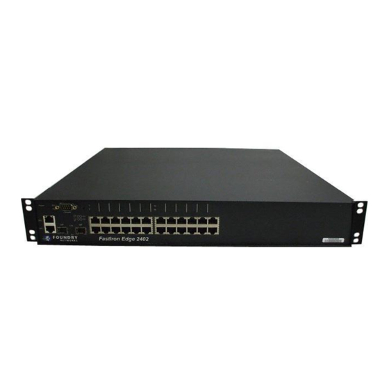
The following figures show the front panels of these FastIron Edge Switches. Figure 2.5 FastIron Edge Switch 2402-POE FastIron Edge 2402 POE Link/Act POWER Power 2 3 4 7 8 9 10 14 15 16 19 20 21 22 CONSOLE LINK June 2006 © 2006 Foundry Networks, Inc. 2 - 5... -
Page 16: Fesx424, Fesx624, And Fwsx424
Optionally, one or two 10-Gigabit Ethernet uplink ports for 10-Gigabit Small Form Factor Pluggable (XFP) MSA-compliant optical transceivers Note that one port out of the first four Copper ports or the four Fiber ports can be active at a time (see “FES 10/ 100/1000 Mbps Ports” on page 2-9). -
Page 17: Fesx424-Poe
48 Copper ports that support 10/100/1000Base-T RJ-45 connectors • Four Gigabit Fiber uplink ports (1F – 4F) for mini-GBIC optical transceivers (also called Small Form Factor Pluggable (SFP) Multisource Agreement (MSA)-compliant optical transceivers) June 2006 © 2006 Foundry Networks, Inc. 2 - 7... -
Page 18: Control Features
MSA-compliant optical transceivers Note that one port out of the first four Copper ports or the four Fiber ports can be active at a time (see “FES 10/ 100/1000 Mbps Ports” on page 2-9). For example, you can use ports 1 –4 of the Gigabit Copper ports or ports 1F –... - Page 19 Copper port 10 or Fiber port 10, but not both at the same time. You can use a combination of fiber and copper ports or all copper or all fiber ports, as needed. On the FES, if you attach both the copper and fiber connectors for a port to the network, the fiber connector takes precedence over the copper connector and will be the active connector for the port.
- Page 20 Foundry Hardware Installation Guide for the FES, FESX, and FWSX LEDs for FES Ports The 10/100 Mbps and 10/100/1000 Mbps ports on FES devices provide status information using the LEDs listed in Table 2.3. Table 2.3: LEDs for FES Ports...
- Page 21 Optionally, one or two 10GBase-LR, SR, or ER Gigabit uplink ports The FES X-Series product family supports auto MDI/MDIX detection for 10/100 ports and Gigabit Copper ports. For more information about this feature, see "Configuring MDI/MDIX" in the FastIron Edge Switch and FastIron Edge Switch X-Series Installation and Basic Configuration Guide.
- Page 22 Foundry Hardware Installation Guide for the FES, FESX, and FWSX LEDs for FESX and FWSX Ports The 10/100/1000 Mbps copper and fiber ports, and the 10 Gbps fiber ports on the FESX and FWSX provide status information using the LEDs listed in Table 2.4.
- Page 23 The port is enabled, a power-consuming port device has been detected, and the module is supplying power to the device. Right for lower port The port is not providing in-line power. June 2006 © 2006 Foundry Networks, Inc. 2 - 13...
- Page 24 Port Regions Except for the FES12GCF, ports on the FES, FESX, and FWSX are grouped into regions. For a few features, including trunk group configuration and port monitoring, you will need to know the region to which a port belongs.
-
Page 25: Fiber Optic Modules
Support for EFM-D optics was added in release 02.2.00 for the FESX and FWSX. • 1000BaseLH • 1000BaseLX – 1000BaseLX uses long wavelength (LX) laser over multimode and single-mode fiber. June 2006 © 2006 Foundry Networks, Inc. 2 - 15... -
Page 26: June 2006
Foundry Hardware Installation Guide for the FES, FESX, and FWSX • 1000BaseSX – 1000BaseSX uses short wavelength (SX) laser over multimode fiber. • 1000BaseSX 2 – Whereas previous releases of 1000BaseSX support a maximum distance of 550 meters, the 1000BaseSX 2 supports a maximum distance of 2000 meters (2 kilometers). -
Page 27: Power Supplies
The following sections provide further details about the power supplies for the FastIron family of switches. For hardware specifications for the power supplies, see the chapter “Hardware Specifications” on page 7-1. June 2006 © 2006 Foundry Networks, Inc. 2 - 17... - Page 28 Foundry Hardware Installation Guide for the FES, FESX, and FWSX RPS5-AC and RPS5-DC Power Supplies The RPS5-AC and RPS5-DC power supplies are supported in the following devices: • FES2402 • FES4802 • FES9604 • FES12GCF The RPS5-AC and RPS5-DC power supplies are 100VAC @ 3.5A, 240 VAC @ 1.5A, 50-60Hz, and are auto- sensing and auto-switching.
- Page 29 Figure 2.15 shows a rear view of a FastIron Stackable device containing one AC power supply. Figure 2.15 RPS8-AC and RPSX-448-AC power supplies AC Power Power Supply locking screw Power Switch Connector Plastic Latch Power Supply (POE) June 2006 © 2006 Foundry Networks, Inc. 2 - 19...
-
Page 30: Cooling System And Fans
The fans in the FES operate at a steady speed, and do not support multiple fan speeds as do the fans in the FESX and FWSX. -
Page 31: T Hresholds
If desired, you can change the settings of the temperature thresholds associated with fan speed switches. For more information, see “Managing the FESX and FWSX Fan Settings and Temperature Sensors” on page 5-3. June 2006 © 2006 Foundry Networks, Inc. 2 - 21... - Page 32 Foundry Hardware Installation Guide for the FES, FESX, and FWSX 2 - 22 © 2006 Foundry Networks, Inc. June 2006...
-
Page 33: Unpacking A System
Chapter 3 Installing a FastIron Stackable Switch WARNING: The procedures in this manual are for qualified service personnel. This chapter describes how to physically install the FES, FESX, and FWSX devices. This chapter contains the following topics: Table 3.1: Chapter Contents... -
Page 34: Package Contents
Foundry Hardware Installation Guide for the FES, FESX, and FWSX Package Contents • Foundry Networks FastIron Edge Switch, FastIron Edge Switch X-Series, or FastIron Workgroup Switch X- Series • 115V AC power cable (for AC sourced devices) • Rack mount brackets and mounting screws •... -
Page 35: Summary Of Installation Tasks
Installing a FastIron Stackable Switch Summary of Installation Tasks Follow the steps listed below to install your FES, FESX, or FWSX device. Details for each of the steps highlighted below are provided in this chapter and in the following chapter. -
Page 36: Installation Precautions
Foundry Hardware Installation Guide for the FES, FESX, and FWSX Table 3.2: Summary of Installation Tasks Task Task Where to Find More Information Number Continue configuring the device using the CLI or the Foundry FastIron X-Series Configuration Web management interface. You also can use IronView Guide or Foundry Switch and Router Network Manager to manage the device. - Page 37 CAUTION: For the DC input circuit to a FES, FESX, or FWSX (DC power supply part number RPS5DC and RPS-X424-DC), make sure there is a 10-amp listed circuit breaker, minimum -48VDC, double pole, on the input to the terminal block.
-
Page 38: Preparing The Installations
Foundry Hardware Installation Guide for the FES, FESX, and FWSX Preparing the Installation Site Cabling Infrastructure Ensure that the proper cabling is installed in the site. See “Hardware Specifications” on page 7-1 or www.foundrynetworks.com for a summary of supported cabling types and their specifications. -
Page 39: Installing A Dc Power Supply
The power supply is right-side up when the power connector is on the left and the fan vent is on the right. June 2006 © 2006 Foundry Networks, Inc. 3 - 7... -
Page 40: Installing The Device
Foundry Hardware Installation Guide for the FES, FESX, and FWSX 10. Press the two latches near the edges of the supply outward to lock the supply in place. 11. If necessary, replace the power supply locking screw. 12. After the power supply is properly inserted, connect the power source to the wires to activate the circuit. -
Page 41: Wall Mount Installation
If the links on these cables are good and the connected device is powered on, the link LEDs will light. For more details on specific LED conditions after system start-up, see the section below, “Observing the June 2006 © 2006 Foundry Networks, Inc. 3 - 9... -
Page 42: Observing The Power Status Leds
Foundry Hardware Installation Guide for the FES, FESX, and FWSX Power Status LEDs” on page 3-10 and “Hardware Specifications” on page 7-1. Observing the Power Status LEDs Table 3.3 lists the LEDs that show power status. The power supplies themselves do not have LEDs. - Page 43 NOTE: As indicated in Figure 3.2 and Figure 3.3, some of the wires should not be connected. If you do connect the wires that are labeled “Reserved”, you might get unexpected results with some terminals. June 2006 © 2006 Foundry Networks, Inc. 3 - 11...
- Page 44 Foundry Hardware Installation Guide for the FES, FESX, and FWSX Figure 3.3 Serial port pin assignments showing cable connection options to a terminal or PC DB-9 to DB-9 DB-9 to DB-25 Female Switch Terminal or PC Female Switch Terminal or PC...
-
Page 45: Connecting Network
User EXEC – The level you enter when you first start a CLI session. At this level, you can view some system information but you cannot configure system or port parameters. June 2006 © 2006 Foundry Networks, Inc. 4 - 1... -
Page 46: Recovering From A Lost Password
Foundry Hardware Installation Guide for the FES, FESX, and FWSX • Privileged EXEC – This level is also called the Enable level and can be secured by a password. You can perform tasks such as manage files on the flash module, save the system configuration to flash, and clear caches at this level. -
Page 47: Configuring Ip Addresses
Privileged EXEC Level FESX Router# configure terminal Global CONFIG Level FESX Router(config)# Configure the IP addresses and mask addresses for the interfaces on the router. FESX Router(config)# int e 2 June 2006 © 2006 Foundry Networks, Inc. 4 - 3... -
Page 48: Devices Running Layer 2 Software
Foundry Hardware Installation Guide for the FES, FESX, and FWSX FESX Router(config-if-e1000-2)# ip address 192.22.3.44 255.255.255.0 NOTE: You can use the syntax ip address <ip-addr>/<mask-bits> if you know the subnet mask length. In the above example, you could enter ip address 192.22.3.44/24. -
Page 49: Connecting Network Devices
For more information about this feature, see the Foundry FastIron X-Series Configuration Guide or the Foundry Switch and Router Installation and Basic Configuration Guide. Figure 4.1 UTP crossover cable UTP Crossover Cable 10/100BaseTX unused unused unused unused unused unused unused unused June 2006 © 2006 Foundry Networks, Inc. 4 - 5... -
Page 50: Connecting To Workstations
Foundry Hardware Installation Guide for the FES, FESX, and FWSX Figure 4.2 Cat-5 crossover cable for 1000BaseT Cat-5 Crossover Cable 1000BaseT NOTE: The 802.3ab standard calls for automatic negotiation of the connection between two 1000BaseT ports. Consequently, a crossover cable may not be required; a straight-through cable may work as well. -
Page 51: Testing Connectivity
See the Foundry Switch and Router Command Line Interface Reference for information about the parameters. NOTE: If you address the ping to the IP broadcast address, the device lists the first four responses to the ping. June 2006 © 2006 Foundry Networks, Inc. 4 - 7... -
Page 52: Observing Leds
Foundry Hardware Installation Guide for the FES, FESX, and FWSX Observing LEDs After you install the network cables, you can observe certain LEDs to determine if the network connections are functioning properly. Table 4.2 outlines the LEDs related to the network connections, the desired state of each LED, possible abnormal states of each LED, and what to do if an LED indicates an abnormal state. -
Page 53: Tracing A Route
To determine the path through which a Foundry device can reach another device, enter a command such as the following at any level of the CLI on the Foundry device: FESX Switch> traceroute 192.33.4.7 June 2006 © 2006 Foundry Networks, Inc. 4 - 9... -
Page 54: Troubleshooting Network Connections
Foundry Hardware Installation Guide for the FES, FESX, and FWSX Syntax: traceroute <host-ip-addr> [maxttl <value>] [minttl <value>] [numeric] [timeout <value>] [source-ip <ip addr>] The CLI displays trace route information for each hop as soon as the information is received. Traceroute requests display all responses to a given TTL. - Page 55 • Shorted: A short is detected in the cable. • Open: An opening is detected in the cable. • ImpedMis: The impedance is mismatched. • Failed: The TDR test failed. June 2006 © 2006 Foundry Networks, Inc. 4 - 11...
- Page 56 Foundry Hardware Installation Guide for the FES, FESX, and FWSX 4 - 12 © 2006 Foundry Networks, Inc. June 2006...
- Page 57 Displaying management module CPU usage Removing MAC address entries Managing FES Temperature Settings This section describes how to display temperature settings on the FES chassis and how to change the temperature warning and shutdown levels. Using the Temperature Sensor on the FES The FES chassis comes with a built-in temperature sensor.
- Page 58 Foundry Hardware Installation Guide for the FES, FESX, and FWSX Displaying the Temperature on the FES By default, the software polls the temperature sensor every 60 seconds to get the current temperature. This poll rate is controlled by the chassis poll time, which also controls how often the software polls other system components.
-
Page 59: Managing The Fesx And Fwsx F
The <value> can be 0 – 125. To change the shutdown temperature, enter a command such as the following at Privileged EXEC level of the CLI: FES Switch# temperature shutdown 57 Syntax: temperature shutdown <value> The <value> can be 0 – 125. -
Page 60: Changing The Chassisp
Foundry Hardware Installation Guide for the FES, FESX, and FWSX Changing the Chassis Polling Interval The procedure for changing the chassis polling interval on the FESX and FWSX is the same as that on the FES device. See “Changing the Chassis Temperature Polling Interval” on page 5-3. -
Page 61: Viewing Fan Speeds
All MAC address entries. • All MAC address entries for a specified Ethernet port. • All MAC address entries for a specified VLAN. • A specified MAC address entry in all VLANs. June 2006 © 2006 Foundry Networks, Inc. 5 - 5... - Page 62 Foundry Hardware Installation Guide for the FES, FESX, and FWSX For example, to remove entries for the MAC address 000d.cb80.00d in all VLANs, enter the following command at the Privileged EXEC level of the CLI: FESX Switch# clear mac-address 000d.cb80.00d0 Syntax: clear mac-address <mac-address>...
-
Page 63: Hardware Maintenance Schedule
Otherwise, you can replace the following hardware components as needed: • Copper and fiber optic modules (SFPs (mini-GBICs) and XFP transceivers) • Power supplies • 10-Gigabit Ethernet module June 2006 © 2006 Foundry Networks, Inc. 6 - 1... -
Page 64: Replacing A Power Supply
• Replacing an power supply. WARNING: Power supplies are hot swappable. However, Foundry Networks recommends that you disconnect the power supply from AC power before installing or removing the supply. The device can be running while a power supply is being installed or removed, but the power supply itself should not be connected to a power source. -
Page 65: Dc Power Supplies
2-17 for a list of which power supplies are supported in which devices, and for illustrations of power supply placement in the Foundry devices. WARNING: Before beginning the installation, see the precautions in “Power Precautions” on page 3-4. June 2006 © 2006 Foundry Networks, Inc. 6 - 3... - Page 66 Foundry Hardware Installation Guide for the FES, FESX, and FWSX Removing a DC Power Supply Turn off the DC power source or disconnect it from the power supply. Loosen the three screws used to hold the wires in the connector, then pull out the wires.
-
Page 67: Verifying Proper Operation
OK – The power supply is functioning properly and supplying power to the chassis and installed modules. • Failed – The power supply is not functioning and is not supplying power to the chassis and installed modules. June 2006 © 2006 Foundry Networks, Inc. 6 - 5... -
Page 68: Disassembling The Chassis
Foundry Hardware Installation Guide for the FES, FESX, and FWSX Installing or Replacing a 10-Gigabit Ethernet Module NOTE: This section applies to the FESX and FWSX devices only. The 1-port and 2-port 10-Gigabit Ethernet modules are optional. You can order the FESX and FWSX with a 10- Gigabit module installed at the factory, or you can later upgrade your device. -
Page 69: Installing A 10-Gigabit Ethernet Module
This section provides information about the following tasks: • Removing a fiber optic module • Installing a new fiber optic module • Cabling a fiber optic module June 2006 © 2006 Foundry Networks, Inc. 6 - 7... -
Page 70: Removing A Fiber Optic Module
Foundry Hardware Installation Guide for the FES, FESX, and FWSX Removing a Fiber Optic Module You can remove a fiber SFP (also called a mini-GBIC) or an XFP from a port while the FastIron Stackable device is powered on and running. -
Page 71: Cabling A Fiber Optic Module
FastIron chassis. You can also purchase this type of cleaner from the following Website: http://www.fisfiber.com/Home_Page.asp When not using an SFP or XFP connector, make sure to keep the protective covering on. June 2006 © 2006 Foundry Networks, Inc. 6 - 9... - Page 72 Foundry Hardware Installation Guide for the FES, FESX, and FWSX 6 - 10 © 2006 Foundry Networks, Inc. June 2006...
-
Page 73: Hardware Specifications
Chapter 7 Hardware Specifications This chapter contains hardware specifications for the Foundry Networks FastIron Stackable devices. This chapter contains the following information: Table 7.1: Chapter Contents Description See Page Chassis specifications Physical dimensions and weight Environmental considerations Cooling system Regulatory compliance... -
Page 74: Chassis Specifications
The following sections present the hardware specifications for the FastIron Stackable devices. Physical Dimensions Table 7.2 lists the physical dimensions and weight for the FastIron family of switches. Table 7.2: Physical Dimensions and Weight of the FES, FESX, and FWSX Platform Height... -
Page 75: Warranty
This section lists the pinouts for the DB-9 connector and RJ-45 port jacks. Serial (Console) Port Pinouts The Console port is a standard male DB-9 connector, as shown in Figure 7.1. June 2006 © 2006 Foundry Networks, Inc. 7 - 3... - Page 76 Foundry Hardware Installation Guide for the FES, FESX, and FWSX Figure 7.1 Serial port pin and signalling details Pin Assignment Pin Number Switch Signal DB-9 male Reserved TXD (output) RXD (input) Reserved Reserved CTS (input) RTS (output) Reserved Most PC serial ports require a cable with a female DB-9 connector. However, terminal connections will vary, requiring a cable with either a DB-9 or DB-25 connector, male or female.
-
Page 77: Cable Specifications
2 – 550 2 – 5000 1000Base-SX 62.5 2 – 200 62.5 2 – 275 2 – 500 2 – 550 1000Base-T 10GBase-ZR 1550 nm up to 80000 (80 km) June 2006 © 2006 Foundry Networks, Inc. 7 - 5... -
Page 78: Power Cords
Foundry Hardware Installation Guide for the FES, FESX, and FWSX Table 7.6: Cable length summary table (Continued) Fiber Type Core Modal Range Diameter Bandwidth (meters) (microns) (MHz*km) or Wavelength (nm) 10GBase-ZRD 1500 nm up to 80000 (80 km) 10GBase-LR 2 – 10000... -
Page 79: Key Features
All power supplies are auto-sensing and auto-switching. Key features See “Power Supplies” on page 2-17 for the key features of the FES, FESX, and FWSX power supplies. Physical Dimensions and Weight Table 7.7: Physical Dimensions and Weight of Power Supplies... -
Page 80: Input Connector
Foundry Hardware Installation Guide for the FES, FESX, and FWSX Table 7.7: Physical Dimensions and Weight of Power Supplies Power Supply Dimensions Weight RPS8-AC 2.46 in (H) x 8.67 in (W) x 7.6 in (D) 6 lbs (2.72 kg) RPSDC-X424-POE 6.25 cm (H) x 22.03 cm (W) x 19.30 cm (D) - Page 81 EN55022 Class A Harmonic Current Emissions (Class A) - EN61000-3-2, with Amendment 14 (1999) Voltage Fluctuations and Flicker - EN61000-3-3 Safety Agency Approvals and Certifications The FES, FESX, and FWSX power supplies comply with the following safety standards: • CSA/cUL • •...
-
Page 82: Environmental Considerations
Foundry Hardware Installation Guide for the FES, FESX, and FWSX Safety Warnings The power supplies are marked with an electrical hazard label and with the safety warnings shown in Table 7.10. Table 7.10: Safety Warning Labels on Power Supplies CAUTION: No operator serviceable parts inside. Refer servicing to qualified personnel. -
Page 83: Electrical Specifications
Output power 220 watts of total output power 600 watts of total output power, including +12VDC @ 10A to the system and -48VDC @ 10 A for Power over Ethernet applications June 2006 © 2006 Foundry Networks, Inc. 7 - 11... - Page 84 Foundry Hardware Installation Guide for the FES, FESX, and FWSX 7 - 12 © 2006 Foundry Networks, Inc. June 2006...
-
Page 85: Appendix 8 Cautions And Warnings
802.3af. Si se instala el suministro de corriente en un dispositivo que no sea el FES2402-POE o el FES4802-POE, se producirán daños de consideración al equipo. June 2006 © 2006 Foundry Networks, Inc. A - 1... -
Page 86: 2006 Foundry Networks, Inc
Foundry Hardware Installation Guide for the FES, FESX, and FWSX CAUTION: Remove the power cord from a power supply before you install it in or remove it from the device. Otherwise, the power supply or the device could be damaged as a result. (The device can be running while a power supply is being installed or removed, but the power supply itself should not be connected to a power source.) - Page 87 CAUTION: For the DC input circuit to an FES, FESX, or FWSX (DC power supply part number RPS5DC and RPS-X424-DC), make sure there is a 10-amp listed circuit breaker, minimum -48VDC, double pole, on the input to the terminal block. The input wiring for connection to the product should be Listed copper wire, 14 AWG, marked VW-1, and rated 90 degrees Celsius.
- Page 88 Kupferdraht (14 AWG gekennzeichnet mit VW-1), der für mindestens 90° C ausgelegt ist, handeln. MISE EN GARDE: Pour le circuit d’alimentation C.C. d’un FES ou FESX (références du bloc d’alimentation C.C. RPS5DC et RPS-X424-DC), assurez-vous de la présence d’un disjoncteur de 10 ampères, minimum –48 V C.C., double coupure, sur l’entrée vers le bloc d’alimentation.
- Page 89 Never leave tools inside the chassis. VORSICHT: Lassen Sie keine Werkzeuge im Chassis zurück. MISE EN GARDE: Ne laissez jamais d'outils à l'intérieur du châssis. PRECAUCIÓN: No deje nunca herramientas en el interior del chasis. June 2006 © 2006 Foundry Networks, Inc. A - 5...
- Page 90 Foundry Hardware Installation Guide for the FES, FESX, and FWSX CAUTION: If you do not install a module in a slot, you must keep the slot panel in place. If you run the chassis with an uncovered slot, the system will overheat.
-
Page 91: Warnings
Monte los instrumentos que instale en un bastidor o armario lo más bajos posible. Ponga el instrumento más pesado en la parte inferior y los instrumentos progresivamente más livianos más arriba. June 2006 © 2006 Foundry Networks, Inc. A - 7... - Page 92 Foundry Hardware Installation Guide for the FES, FESX, and FWSX WARNING: Disconnect the power cord from all power sources to completely remove power from the device. ACHTUNG: Ziehen Sie das Stromkabel aus allen Stromquellen, um sicherzustellen, dass dem Gerät kein Strom zugeführt wird.
- Page 93 Netzteils laufen. Nur das Netzteil sollte nicht an eine Stromquelle angeschlossen sein. Ansonsten können Sie verletzt oder das Netzteil bzw. andere Geräteteile beschädigt werden. AVERTISSEMENT: Les blocs d'alimentation peuvent être changés à chaud. Cependant, Foundry Networks vous conseille de débrancher le bloc d'alimentation de l'alimentation C.A. avant d'installer ou d'enlever le bloc d'alimentation.
- Page 94 Foundry Hardware Installation Guide for the FES, FESX, and FWSX WARNING: Be careful not to accidently insert your fingers into the fan tray while removing it from the chassis. The fan may still be spinning at a high speed. ACHTUNG: Die Finger dürfen nicht versehentlich in das Ventilatorblech gesteckt werden, wenn dieses...
Need help?
Do you have a question about the FES and is the answer not in the manual?
Questions and answers