
Related Manuals for Foundry Networks FES2402


Summary of Contents for Foundry Networks FES2402
- Page 1 Foundry® FastIron Compact Switch Hardware Installation Guide FastIron Edge Switch FastIro Edge Switch X Series FastIron Workgroup Switch X Series FES 04.1.00 FSX 05.0.00 Release Date: December 16, 2008 Publish Date: December 15, 2008...
- Page 2 You are not permitted to use these Marks without the prior written consent of Foundry or such appropriate third party. Foundry Networks, BigIron, Terathon, FastIron, IronView, JetCore, NetIron, ServerIron, TurboIron, IronWare, EdgeIron, IronPoint, SecureIton, the Iron family of marks and the Foundry Logo are trademarks or registered trademarks of Foundry Networks, Inc.
-
Page 3: Table Of Contents
EATURES POE A ............................2-3 PPLICATIONS ..........................2-3 IRELESS PPLICATIONS ............................2-4 UPPORT ..........................2-4 ARDWARE EATURES FES2402, FES4802, FES9604 ......................2-4 FES12GCF ............................2-5 FES2402-POE FES4802-POE ....................2-5 FESX424, FESX624, FESX624E-PREM6 FWSX424 ...............2-6 FESX424HF, FESX624HF, FESX624HFE-PREM6 ..............2-7 FESX424-POE ...........................2-8 FESX448, FESX648, FESX648E-PREM6 FWSX448 ..............2-8 ..........................2-9 ONTROL... - Page 4 THERNET OR THERNET ..............4-8 ONNECTING TO ORKSTATIONS ERVERS OUTERS ................4-8 ONNECTING A ETWORK EVICE TO A IBER CX4 T .........................4-9 SING A RANSCEIVER ..........................4-10 ESTING ONNECTIVITY IP A ........................4-10 INGING AN DDRESS ..........................4-10 BSERVING © 2008 Foundry Networks, Inc. December 2008...
- Page 5 ......................6-6 ISASSEMBLING THE HASSIS 10-G ..................6-6 EMOVING A IGABIT THERNET ODULE 10-G ..................6-7 NSTALLING A IGABIT THERNET ODULE ......................6-7 ASSEMBLING THE HASSIS CPU DIMM ..........................6-8 EPLACING A ......................6-8 EPLACING A IBER PTIC ODULE December 2008 © 2008 Foundry Networks, Inc.
- Page 6 ETAILED ROCEDURES ........................A-8 ARDWARE NSTALLATION ........................A-9 OFTWARE NSTALLATION PPENDIX ................B-1 EGULATORY TATEMENTS U.S.A............................... B-1 ......................... B-1 NDUSTRY ANADA TATEMENT ........................... B-1 UROPE AND USTRALIA ............................... B-1 APAN ..............................B-2 OREA © 2008 Foundry Networks, Inc. December 2008...
- Page 7 Contents PPENDIX ................C-1 AUTIONS AND ARNINGS ..............................C-1 AUTIONS .............................. C-10 ARNINGS December 2008 © 2008 Foundry Networks, Inc.
- Page 8 Foundry Hardware Installation Guide for the FES, FESX, and FWSX viii © 2008 Foundry Networks, Inc. December 2008...
-
Page 9: About This Guide
Chapter 1 About This Guide Introduction This guide describes the following product families from Foundry Networks: • FastIron Edge Switch (FES) Layer 2/Layer 3 Switch • FastIron Edge Switch X Series (FESX) Layer 2/Layer 3 Switch • FastIron Workgroup Switch X Series (FWSX) Layer 2 Switch This guide includes procedures for installing the hardware and configuring essential, basic parameters such as permanent passwords and IP addresses. -
Page 10: Audience
How to Get Help or Report Errors Foundry Networks is committed to ensuring that your investment in our products remains cost-effective. If you need assistance or find errors in the manuals, contact Foundry Networks using one of the following options. 1 - 2 ©... -
Page 11: Web Access
Telephone Access 1.877.TURBOCALL (887.2622) – United States 1.408.207.1600 – Outside the United States Warranty Coverage Contact Foundry Networks using any of the methods listed above for information about the standard and extended warranties. December 2008 © 2008 Foundry Networks, Inc. - Page 12 Foundry Hardware Installation Guide for the FES, FESX, and FWSX 1 - 4 © 2008 Foundry Networks, Inc. December 2008...
-
Page 13: Chapter 2 Product Overview
Chapter 2 Product Overview This chapter contains an overview of the following Foundry Networks FastIron family of compact switches: • FastIron Edge Switch® (FES) Layer 2 / Layer 3 Switch • FastIron Edge Switch X Series® (FESX) Layer 2 / Layer 3 Switch •... -
Page 14: Supported Configurations
Switching only. Premium (PREM) devices support full Layer 2 Switching and full Layer 3 multiprotocol routing. All FES and FESX devices can be upgraded to premium models, meaning all models can support full Layer 3 2 - 2 © 2008 Foundry Networks, Inc. December 2008... -
Page 15: Poe Applications
POE technology eliminates the need for an electrical outlet and dedicated UPS near IP powered devices. With power sourcing devices, such as Foundry’s FES2402-POE and FES4802-POE, power is consolidated and centralized in the wiring closets, improving the reliability and resiliency of the network. Because POE can provide power over Ethernet cable, power is continuous, even in the event of a power failure. -
Page 16: Ipv6 Support
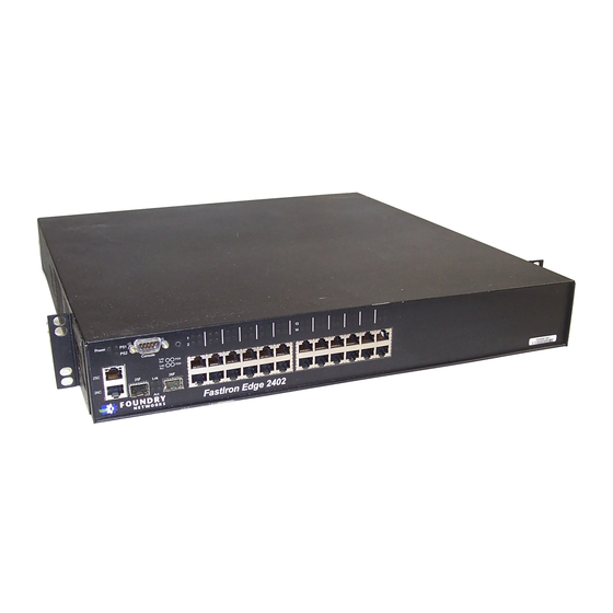
The FastIron Edge Switch (FES) family provides high 10/100 port density and 10/100/1000 Gigabit Ethernet uplinks in a compact form factor. • The FES2402 has 24 10/100 ports and two Gigabit uplink ports. • The FES4802 has 48 10/100 ports and two Gigabit uplink ports. -
Page 17: Fes12Gcf
LINK FES2402-POE and FES4802-POE • The FES2402-POE has 24 10/100 ports and two Gigabit uplink ports. • The FES4802-POE has 48 10/100 ports and two Gigabit uplink ports. The following figures show the front panels of these FastIron Edge Switches. -
Page 18: Fesx424, Fesx624, Fesx624E-Prem6 And Fwsx424
The following figure shows the front panel of the FESX424. The FWSX424 front panel looks similar to the FESX424, except for the model number on the front of the device. 2 - 6 © 2008 Foundry Networks, Inc. December 2008... -
Page 19: Fesx424Hf, Fesx624Hf, And Fesx624Hfe-Prem6
Console Power The following figure shows the front panel of the FESX624HF. The FESX624HFE-PREM6 front panel looks similar to the FESX624HF, except for the model number on the front panel. December 2008 © 2008 Foundry Networks, Inc. 2 - 7... -
Page 20: Fesx424-Poe
IPv4 (FESX4 and FWSX) devices optionally support one or two 10-Gigabit Ethernet uplink ports for 10- Gigabit Small Form Factor Pluggable (XFP) MSA-compliant optical transceivers • IPv6 (FESX6) devices optionally support two 10-Gigabit Ethernet uplink ports for 10-Gigabit Small Form 2 - 8 © 2008 Foundry Networks, Inc. December 2008... -
Page 21: Control Features
PC. A straight-through EIA/TIA DB-9 serial cable (M/F) ships with the device. The serial management interface (the port labeled Console) is located in the left corner of the front panel. December 2008 © 2008 Foundry Networks, Inc. 2 - 9... - Page 22 Web management interface. The button is located to the right of the serial management interface and is recessed to prevent it from being pushed accidentally. FES Network Interfaces The FES2402, 4802, and 9604 provide the following interfaces: • 10Base-T/100Base-T (10/100) copper ports •...
-
Page 23: December 2008 © 2008 Foundry Networks, Inc
Green Copper port is connected on upper copper connector for connector. upper copper connector Amber Traffic is being transmitted and received on upper copper connector. December 2008 © 2008 Foundry Networks, Inc. 2 - 11... - Page 24 XFP MSA-compliant 10GBase-LR, 10GBase-SR, or 10GBase-ER – fiber cabling. If your device does not include a 10-GbE module, you can optionally install one. See “Installing or Replacing a 10-Gigabit Ethernet Module” on page 6-6. 2 - 12 © 2008 Foundry Networks, Inc. December 2008...
- Page 25 The POE ports (1 – 24) use the round LEDs located beneath the copper ports. The first (left-most) LED is for port 1, the second LED is for port 2, the third LED is for port 3, etc.. December 2008 © 2008 Foundry Networks, Inc. 2 - 13...
- Page 26 The port is enabled, a power-consuming port device has been detected, and the module is supplying power to the device. Right for lower port The port is not providing in-line power. 2 - 14 © 2008 Foundry Networks, Inc. December 2008...
- Page 27 Ports 65 – 72 • Ports 73 – 80 • Ports 81 – 88 • Ports 89 – 96 • Port 97 • Port 98 • Port 99 • Port 100 December 2008 © 2008 Foundry Networks, Inc. 2 - 15...
-
Page 28: Network Interfaces
The output of the show media command displays the type of media installed in the ports. NOTE: The show media output on FES devices display fiber media only. These devices do not display the copper media installed in the ports. 2 - 16 © 2008 Foundry Networks, Inc. December 2008... -
Page 29: Power Supplies
AC and DC supplies in the same device. The following table lists the power supplies that may be installed in a FastIron compact switch. Table 2.5 and Table 2.6 show which Foundry power supply can be installed on each Foundry FastIron compact product. December 2008 © 2008 Foundry Networks, Inc. 2 - 17... - Page 30 The remaining supply provides enough power for all the ports. The following sections provide further details about the power supplies for the FastIron family of switches: 2 - 18 © 2008 Foundry Networks, Inc. December 2008...
- Page 31 POE ports are enabled based on their priority settings. Keep in mind that the system will reserve the maximum configured power per POE-enabled port, even if the POE power-consuming device is drawing less power. December 2008 © 2008 Foundry Networks, Inc. 2 - 19...
- Page 32 A FastIron POE compact switch with dual power supplies may not provide redundancy, depending on how much power the POE ports are consuming. In a POE device with redundant power supplies, power consumption is 2 - 20 © 2008 Foundry Networks, Inc. December 2008...
-
Page 33: Cooling System And Fans
For more information, see “Managing Temperature Settings and Fan Speed on FastIron X Series Compact Switches” on page 5-3. December 2008 © 2008 Foundry Networks, Inc. 2 - 21... - Page 34 Foundry Hardware Installation Guide for the FES, FESX, and FWSX 2 - 22 © 2008 Foundry Networks, Inc. December 2008...
-
Page 35: Installing A Fast Iron
The Foundry systems ship with all of the following items. Please review the list below and verify the contents. If any items are missing, please contact the place of purchase. Package Contents • Foundry Networks FastIron compact switch • 115V AC power cable (for AC sourced devices) •... -
Page 36: Summary Of Installation Tasks
“Connecting Network Devices” on page 4-6 addresses, the system is ready to accept network equipment. Test IP connectivity to other devices by pinging them “Testing Connectivity” on page 4-10 and tracing routes. 3 - 2 © 2008 Foundry Networks, Inc. December 2008... -
Page 37: Installation Precautions
Power Precautions CAUTION: Use a separate branch circuit for each AC power cord, which provides redundancy in case one of the circuits fails. December 2008 © 2008 Foundry Networks, Inc. 3 - 3... - Page 38 The RPS8-AC power supply is designed exclusively for use with the FES2402-POE and FES4802- POE devices. The power supply produces extensive power to support 802.3af applications. Installing the power supply in a device other than the FES2402-POE or FES4802-POE will cause extensive damage to your equip- ment.
-
Page 39: Preparing The Installations
With one hand, hold the bar on the front panel of the power supply. With the other hand, support the underside of the power supply, and insert the power supply into the empty power supply slot. Press until the December 2008 © 2008 Foundry Networks, Inc. 3 - 5... -
Page 40: Installing A Dc Power Supply
Press until the supply is completely in the slot, so that the connectors on the back of the supply are fully engaged with the pins on the power backplane. 3 - 6 © 2008 Foundry Networks, Inc. December 2008... -
Page 41: Installing The Device
(19 inches), which you can order separately from Foundry Networks (part number 70166-000). Use the long mounting brackets to prevent the Foundry device from sagging when installed in a non-compliant (non-Telco) equipment rack. - Page 42 Mount the device in the rack as illustrated in Figure 3.3. NOTE: Although Figure 3.3 shows a device with short mounting brackets, the procedure for securing a device with long mounting brackets is the same. 3 - 8 © 2008 Foundry Networks, Inc. December 2008...
-
Page 43: Powering O N The System
If your device has more than one power supply installed, repeat this procedure for each power supply. Connect the power cord supplied with the device to the power connector on the power supply on the rear of the device. December 2008 © 2008 Foundry Networks, Inc. 3 - 9... -
Page 44: Observing The Power Status Leds
Foundry Hardware Installation Guide for the FES, FESX, and FWSX Insert the other end into a properly grounded electrical outlet. For the FES2402-POE and FES4802-POE with power supply model RPS8, turn the power switch to the ON position. NOTE: The non-POE devices use power supply model RPS5, which do not have power switches. They power on when you connect a power cord to the device and to a power source. -
Page 45: Attaching Apc Or Terminal
The EIA/TIA 232 serial communication port serves as a connection point for management by a PC or SNMP workstation. Foundry switches and Layer 3 Switches come with a standard male DB-9 connector, shown in Figure 3.4. December 2008 © 2008 Foundry Networks, Inc. 3 - 11... - Page 46 Serial port pin assignments showing cable connection options to a terminal or PC DB-9 to DB-9 DB-9 to DB-25 Female Switch Terminal or PC Female Switch Terminal or PC Reserved Reserved Reserved Reserved Reserved Reserved Reserved Reserved 3 - 12 © 2008 Foundry Networks, Inc. December 2008...
-
Page 47: Connecting Network
Privileged EXEC – This level is also called the Enable level and can be secured by a password. You can perform tasks such as manage files on the flash module, save the system configuration to flash, and clear caches at this level. December 2008 © 2008 Foundry Networks, Inc. 4 - 1... -
Page 48: Recovering From A Lost Password
Enter no password at the prompt. (You cannot abbreviate this command.) Enter boot system flash primary at the prompt. This command causes the device to bypass the system password check. After the console prompt reappears, assign a new password. 4 - 2 © 2008 Foundry Networks, Inc. December 2008... -
Page 49: Configuring Ip Addresses
FastIron(config-if-e1000-5)# ip address 192.22.3.44 255.255.255.0 NOTE: You can use the syntax ip address <ip-addr>/<mask-bits> if you know the subnet mask length. In the above example, you could enter ip address 192.22.3.44/24. December 2008 © 2008 Foundry Networks, Inc. 4 - 3... -
Page 50: Ipv6 Devices
Foundry IPv6 devices support the 128-bit addressing format, composed of 8 fields of 16-bit hexadecimal values separated by colons (:). For example, 2001:0000:0000:0200:002D:D0FF:FE48:4672 is an IPv6 address, which can also be expressed as 2001:0:0:200:2D:D0FF:FE48:4672 after ommitting the leading zeros. 4 - 4 © 2008 Foundry Networks, Inc. December 2008... - Page 51 <prefix-length> parameter. IPv6 Devices Running Layer 2 Software To configure an IPv6 address to a device running Layer 2 software: At the opening CLI prompt, enter enable. December 2008 © 2008 Foundry Networks, Inc. 4 - 5...
-
Page 52: Connecting Network Devices
For copper connections to Ethernet hubs, a 10/100BaseTX or 1000BaseT switch, or another Foundry device, a crossover cable is required (Figure 4.1 and Figure 4.2). If the hub is equipped with an uplink port, it will require a straight-through cable instead of a crossover cable. 4 - 6 © 2008 Foundry Networks, Inc. December 2008... - Page 53 “Enabling and Disabling Support for 100Base-TX” in the Foundry FastIron Configuration Guide. NOTE: This module requires a Cat5 cable and uses an RJ45 connector. Hotswap is supported for this module when it is configured in 100M mode. December 2008 © 2008 Foundry Networks, Inc. 4 - 7...
-
Page 54: Connecting To Workstations
Remove the protective covering from the fiber-optic port connectors and store the covering for future use. Before cabling a fiber optic module, Foundry strongly recommends cleaning the cable connectors and the port connectors. For more information, see “Cleaning the Fiber-Optic Connectors” on page 4-9. 4 - 8 © 2008 Foundry Networks, Inc. December 2008... -
Page 55: Using Acx4 Transceiver
CX4 transceivers. The CX4 transceiver requires a 15 meter CX4-grade cable with 24 or 26 American Wire Gauge (AWG). This cable can be purchased from Foundry Networks. Refer to part number CAB-CX4-0050 when ordering. NOTE: The CX4 transceiver is not hot-swappable. -
Page 56: Pinging An Ip Address
Table 4.2 outlines the LEDs related to the network connections, the desired state of each LED, possible abnormal states of each LED, and what to do if an LED indicates an abnormal state. 4 - 10 © 2008 Foundry Networks, Inc. December 2008... -
Page 57: Port
To determine the path through which a Foundry device can reach another device, enter a command such as the following at any level of the CLI on the Foundry device: FastIron> traceroute 192.33.4.7 December 2008 © 2008 Foundry Networks, Inc. 4 - 11... -
Page 58: Troubleshooting Network Connections
XFP or SFP manufacturer’s recommended thresholds. For details about this feature and how to configure it, see the section “Digital Optical Monitoring” in the Foundry FastIron Configuration Guide. 4 - 12 © 2008 Foundry Networks, Inc. December 2008... -
Page 59: Viewing The Chassis Type
Boot Prom MAC: 000c.dbda.79a0 Managing FES Temperature Settings This section describes how to display temperature settings on the FES switch and how to change the temperature warning and shutdown levels. December 2008 © 2008 Foundry Networks, Inc. 5 - 1... -
Page 60: Displaying The Temperature On A
The following methods describe how to view the system log on the device. If you have configured the device to use a Syslog server or SNMP trap receiver, see the documentation for the server or receiver. 5 - 2 © 2008 Foundry Networks, Inc. December 2008... - Page 61 To change the chassis poll time, enter a command such as the following at the global CONFIG level of the CLI: FastIron(config)#chassis poll-time 200 Syntax: chassis poll-time <value> The <value> can be 0 – 65535. Managing Temperature Settings and Fan Speed December 2008 © 2008 Foundry Networks, Inc. 5 - 3...
-
Page 62: Temperature Sensors
NOTE: This section applies to FastIron X Series compact switches with 48 ports. It does not apply to switches with 24 ports, since the fans in the 24-port switches operate at single speed. 5 - 4 © 2008 Foundry Networks, Inc. December 2008... - Page 63 Default Warning Temperature Default Shutdown Temperature FESX424 64° C 80° C FESX448 80° C 90° C FESX424HF 85° C 90° C FESX424-POE 85° C 90° C FESX624 64° C 80° C December 2008 © 2008 Foundry Networks, Inc. 5 - 5...
-
Page 64: Changing The Temperature
3, enter that fan speed. For the <low-temperature-mark> and <high-temperature-mark> parameters, you can specify any temperature in Centigrade. However, when changing low and high temperature thresholds for a fan speed, remember that the 5 - 6 © 2008 Foundry Networks, Inc. December 2008... - Page 65 Exhaust Side Temperature Readings: Current temperature : 29.5 deg-C Warning level..: 85.0 deg-C Shutdown level..: 125.0 deg-C Intake Side Temperature Readings: Current temperature : 19.0 deg-C Boot Prom MAC: 0000.789a.654c December 2008 © 2008 Foundry Networks, Inc. 5 - 7...
- Page 66 Current temperature : 35.5 degrees Celsius Warning level..: 64.0 degrees Celsius Shutdown level..: 80.0 degrees Celsius Intake Side Temperature Readings: Current temperature : 29.0 degrees Celsius Boot Prom MAC: 00e0.5200.0100 5 - 8 © 2008 Foundry Networks, Inc. December 2008...
-
Page 67: Displaying Management Module Cpu Usage
HHHH.HHHH.HHHH. Use the ethernet <port-num> parameter to remove all MAC addresses for a specified Ethernet port. Use the vlan <number> parameter to remove all MAC addresses for a specified VLAN. December 2008 © 2008 Foundry Networks, Inc. 5 - 9... - Page 68 Foundry Hardware Installation Guide for the FES, FESX, and FWSX 5 - 10 © 2008 Foundry Networks, Inc. December 2008...
-
Page 69: Installation Precautions And Determining Which Power
• Replacing a power supply. WARNING: Power supplies are hot swappable. However, Foundry Networks recommends that you disconnect the power supply from AC power before installing or removing the supply. The device can be running while a power supply is being installed or removed, but the power supply itself should not be connected to a power source. -
Page 70: Switch
If necessary, replace the power supply locking screw. Installing an AC Power Supply To install an AC power supply, do the following: 6 - 2 © 2008 Foundry Networks, Inc. December 2008... -
Page 71: Dc Power Supplies
Insert a new supply, or place the cover plate over the empty power supply bay and press the two latches near the edges of the supply outward to lock the plate into place. If necessary, replace the power supply locking screw. December 2008 © 2008 Foundry Networks, Inc. 6 - 3... - Page 72 After the FastIron device powers on, you can observe the LEDs on the front of the device to verify that it initialized successfully. Table 6.1 outlines the LEDs, the desired state of each LED, possible abnormal states of each LED, and what to do if an LED indicates an abnormal state. 6 - 4 © 2008 Foundry Networks, Inc. December 2008...
- Page 73 OK – The power supply is functioning properly and supplying power to the chassis and installed modules. • Failed – The power supply is not functioning and is not supplying power to the chassis and installed modules. December 2008 © 2008 Foundry Networks, Inc. 6 - 5...
-
Page 74: Disassembling The Chassis
Remove the 10-Gigabit module: • Unplug the power cable from the rear of the 10-Gigabit module. • Use a #2 Phillips-head screwdriver to loosen and remove the three screws on the 10-Gigabit module. 6 - 6 © 2008 Foundry Networks, Inc. December 2008... - Page 75 Once the cover and power supplies are properly positioned, re-fasten the screws on each side of the cover. If the device is rack-mounted, replace the mounting brackets. Replace the screw that secures the power supplies in place. December 2008 © 2008 Foundry Networks, Inc. 6 - 7...
-
Page 76: Removing A Fiber Optic Module
Put on the ESD wrist strap and ground yourself by attaching the clip end to a metal surface (such as an equipment rack). Disconnect the fiber cable connector from the port connector. Insert the protective covering into the port connectors. 6 - 8 © 2008 Foundry Networks, Inc. December 2008... -
Page 77: Installing A New Fiber Optic Module
Observe the link and active LEDs to determine if the network connections are functioning properly. For more information about the LED indicators, see Table 4.2 on page 4-11. December 2008 © 2008 Foundry Networks, Inc. 6 - 9... -
Page 78: Cleaning The Fiber-Optic Connectors
Upgrading the Device to Run Layer 3 Software You can upgrade the FastIron X Series chassis to run Layer 3 code. To do so, follow the instructions In “Layer 3 Upgrade Procedures” on page A-1. 6 - 10 © 2008 Foundry Networks, Inc. December 2008... -
Page 79: Hardware Specifications
Chapter 7 Hardware Specifications This chapter contains chassis and power supply specifications for the Foundry Networks FastIron compact switches. Chassis Specifications The following sections present the hardware specifications for the FastIron Stackable devices. Physical Dimensions Table 7.1 lists the physical dimensions and weight for the FastIron family of switches. -
Page 80: Environmental Considerations
Table 7.2: Environmental Conditions for the Chassis Description Range Operating Environment ° ° ° ° Operating temperature – 104 F (0 – 40 Operating altitude 0 – 6,600 ft. (0 – 2000 meters) 7 - 2 © 2008 Foundry Networks, Inc. December 2008... -
Page 81: British Thermal Units (Btus)
The following are the maximum BTUs for the following devices: • FES and FESX non-POE devices: 340 BTU/Hr (100 watts) per power supply • FES2402-POE: 316 BTU/Hr (580 watts) per power supply • FES4802-POE: 462 BTU/Hr (580 watts) per power supply Cooling The cooling fans cool the CPU, main memory, and voltage regulators. -
Page 82: Regulatory Compliance
Table 7.5 lists the Mean Time Between Failure (MTBF) for the FastIron compact switches. The MTBF is the average estimated time, in units of hours, before a hardware failure may occur. 7 - 4 © 2008 Foundry Networks, Inc. December 2008... - Page 83 FES12GCF + 12 optics + two power supplies 121,959 ° FES2402 + one DC power supply 135,260 ° FES2402-POE + two optics + one power supply 118,888 ° FES2402-POE + two optics + two power supplies 181,061 ° FES4802 + one DC power supply 119,588 °...
- Page 84 FESX448 + one 10 GbE uplink + one XFP + four 115,875 SFPs + two RPS5 power supplies ° FESX448 + one 10 GbE uplink + two XFPs + four 92,601 SFPs + one RPS5 power supply 7 - 6 © 2008 Foundry Networks, Inc. December 2008...
- Page 85 + one XFP + four SFPs + two RPS5 power supplies ° FESX628E-PREM6 or FESX648 + one 10 GbE 86,242 uplink + two XFPs + four SFPs + one RPS5 power supply December 2008 © 2008 Foundry Networks, Inc. 7 - 7...
-
Page 86: Pinouts And Signaling
NOTE: As indicated in Figure 7.1 and Figure 7.2, some of the wires should not be connected. If you do connect the wires that are labeled “Reserved”, you might get unexpected results with some terminals. 7 - 8 © 2008 Foundry Networks, Inc. December 2008... -
Page 87: Cable Specifications
NOTE: Cable installation and network configuration will affect overall transmission capability. The numbers provided below represent the accepted recommendations of the various standards. For network-specific recommendations, consult your local Foundry reseller or system engineer. December 2008 © 2008 Foundry Networks, Inc. 7 - 9... - Page 88 2000 (2 SFP module 100Base-FX IR LC connector for 1310nm up to 15000 SFP module (15km) 100Base-FX LR LC connector for 1310nm up to 40000 SFP module (40km) 7 - 10 © 2008 Foundry Networks, Inc. December 2008...
-
Page 89: Power Cords
All of the FastIron devices ship with US-compatible power cords unless otherwise specified at the time of order. United Kingdom- and European-compatible power cords are also available. See also “Input Connector and Plug” on page 7-14 December 2008 © 2008 Foundry Networks, Inc. 7 - 11... -
Page 90: Power Supply Specifications
“Environmental Considerations” on page 7-13 • “Electrical Specifications” on page 7-13 • “Input Connector and Plug” on page 7-14 • “Regulatory Compliance” on page 7-15 • “Safety Warnings” on page 7-16 7 - 12 © 2008 Foundry Networks, Inc. December 2008... -
Page 91: Physical Dimensions And Weight
+85 Storage altitude up to 15,000 feet above sea level up to 15,000 feet above sea level Electrical Specifications Table 7.9 lists the electrical specifications for the power supplies. December 2008 © 2008 Foundry Networks, Inc. 7 - 13... -
Page 92: Input Connector And Plug
Orientation: Ground pin down All DC Power 3-position Phoenix Contact Supplies The power supply is connected to Earth Ground using wire attached to the ground stud on the power supply rear panel. 7 - 14 © 2008 Foundry Networks, Inc. December 2008... -
Page 93: Regulatory Compliance
This section contains regulatory standards for the power supplies, including the following: • Electromagnetic Compatibility (EMC) compliance • Immunity regulations • Safety certifications • Safety warning labels • Environmental standards December 2008 © 2008 Foundry Networks, Inc. 7 - 15... -
Page 94: Safety Warnings
Partes adentro no reparables por el operador. Refiera reparo a personal autorizado. ATTENTION: Entretien et répartions internes ne sont autorisés qu’au personnel technique qualifié. ACHTUNG: Zugang zur Bedienung nicht erförderlich. Wartung nur durch qualifiziertes Personal. 7 - 16 © 2008 Foundry Networks, Inc. December 2008... -
Page 95: Layer 3 Upgrade Procedures
Upgrade instructions (this document) • Dual Inline Package (DIP) key (also called a PROM) that has eight pins. You should have one of the part numbers listed in Table A.1. December 2008 © 2008 Foundry Networks, Inc. A - 1... - Page 96 FastIron stackable switches do not support the Layer 3 upgrade kits designed for the FastIron chassis switches. Likewise, FastIron chassis devices do not support the Layer 3 upgrade kits designed for the FastIron stackable switches. A - 2 © 2008 Foundry Networks, Inc. December 2008...
- Page 97 Rear Front Side Note: If rack mount ears are installed, remove the four screws from each ear. The following illustrations show the DIP key insertion and settings. December 2008 © 2008 Foundry Networks, Inc. A - 3...
- Page 98 Pin 1 DIP key for upgrade Port Connectors Figure A.3 DIP Key Insertion for FES2402 and FES2402-POE Rear CAUTION: PIN 1 MUST GO HERE! If you accidentally insert the upgrade DIP backwards, Memory...
- Page 99 If you accidentally insert the upgrade DIP backwards, the device will not work and U1005 may be damaged when you power it on. Pin 1 DIP key for upgrade Port Connectors December 2008 © 2008 Foundry Networks, Inc. A - 5...
- Page 100 If you accidentally insert the upgrade DIP backwards, the device will not work and may be damaged when you power it on. Pin 1 DIP key for upgrade Port Connectors A - 6 © 2008 Foundry Networks, Inc. December 2008...
-
Page 101: Installation Overview
Layer 3 software image. Otherwise, go to Step 10. 10. Install the full Layer 3 software. Note the precautions in “Before Installing the Software” on page A-9. 11. Reboot the device. December 2008 © 2008 Foundry Networks, Inc. A - 7... -
Page 102: Detailed Procedures
Pin 1 Semicircular indentation Align the semicircular indentation on the DIP key with the semicircular cut-out on the DIP socket. See the appropriate illustration: • “DIP Key Insertion for FES12GCF” on page A-4 A - 8 © 2008 Foundry Networks, Inc. December 2008... -
Page 103: Software Installation
Layer 3 Upgrade Procedures • “DIP Key Insertion for FES2402 and FES2402-POE” on page A-4 • “DIP Key Insertion for FES4802, FES4802-POE, and FES9604” on page A-5 • “DIP Key Insertion for FESX424, FESX424-POE, and FESX624” on page A-5 •... - Page 104 If you normally boot the device from a TFTP or BootP server, enter the following command at the Privileged EXEC level of the CLI to reboot the device using the new software: boot system tftp | bootp A - 10 © 2008 Foundry Networks, Inc. December 2008...
- Page 105 Verify that the device booted using the Layer 3 software by observing the boot messages. The “SW” area lists the software running on the device. You also can display this information by entering the show version command. December 2008 © 2008 Foundry Networks, Inc. A - 11...
- Page 106 Foundry Hardware Installation Guide for the FES, FESX, and FWSX A - 12 © 2008 Foundry Networks, Inc. December 2008...
-
Page 107: Appendix B Regulatory Statements
Europe and Australia This is a Class A product. In a domestic environment this product may cause radio interference in which case the user may be required to take adequate measures. Japan December 2008 © 2008 Foundry Networks, Inc. B - 1... -
Page 108: Korea
This apparatus has radio wave acceptability registration as a Class A device, so sellers or users should be aware of this. If it is sold or purchased incorrectly, it should be exchanged with a home apparatus (Class B). B - 2 © 2008 Foundry Networks, Inc. December 2008... -
Page 109: Cautions And Warnings
“Vorsicht” weist auf die Gefahr einer möglichen Beschädigung des Gerätes in. Une mise en garde attire votre attention sur un risque possible d'endommagement de l'équipement. Ci-dessous, vous trouverez les mises en garde utilisées dans ce manuel. December 2008 © 2008 Foundry Networks, Inc. C - 1... - Page 110 FES2402-POE y FES4802- POE. El suministro de corriente produce suficiente energía para abastecer a las aplicaciones 802.3af. Si se instala el suministro de corriente en un dispositivo que no sea el FES2402-POE o el FES4802- POE, se producirán daños de consideración al equipo.
- Page 111 Cautions and Warnings PRECAUCIÓN: No instale el instrumento en un entorno en el que la temperatura ambiente de operación pueda exceder los 40°C (104°F). December 2008 © 2008 Foundry Networks, Inc. C - 3...
- Page 112 Compare esta suma con el límite nominal para el circuito. Las capacidades nominales de corriente máximas están generalmente impresas en los instrumentos, cerca de los conectores de corriente de entrada. C - 4 © 2008 Foundry Networks, Inc. December 2008...
- Page 113 For a DC system (DC power supply part number RPSDC-X424-POE), use a grounding wire of at least 10 American Wire Gauge (AWG). The 10 AWG wire should be attached to an agency-approved crimp connector, crimped with the proper tool. December 2008 © 2008 Foundry Networks, Inc. C - 5...
- Page 114 RPSDC-X424-POE), utilice un cable de conexión a tierra de calibre de cable norteamericano (AWG) número 10. El cable 10 AWG deberá acoplarse a un conector engarzado aprobado, y engarzado con la herramienta apropiada. C - 6 © 2008 Foundry Networks, Inc. December 2008...
- Page 115 If you accidentally do erase the configuration on a configured system, enter the write memory command to save the running configuration to the startup- config file. December 2008 © 2008 Foundry Networks, Inc. C - 7...
- Page 116 Si usted borra accidentalmente la configuración en un sistema ya configurado, introduzca el comando write memory (escribir memoria) para guardar la configuración en ejecución en el archivo startup- config. C - 8 © 2008 Foundry Networks, Inc. December 2008...
- Page 117 Si se realizan cambios o modificaciones en este dispositivo sin la autorización expresa de la parte responsable del cumplimiento de las normas, la licencia del usuario para operar este equipo puede quedar anulada. December 2008 © 2008 Foundry Networks, Inc. C - 9...
- Page 118 "Achtung" weist auf eine mögliche Gefährdung hin, die zu Verletzungen oder Tod führen können. Sie finden die folgenden Warnhinweise in diesem Handbuch: Un avertissement attire votre attention sur un risque possible de blessure ou de décès. Ci-dessous, vous trouverez les avertissements utilisés dans ce manuel. C - 10 © 2008 Foundry Networks, Inc. December 2008...
- Page 119 Monte los instrumentos que instale en un bastidor o armario lo más bajos posible. Ponga el instrumento más pesado en la parte inferior y los instrumentos progresivamente más livianos más arriba. December 2008 © 2008 Foundry Networks, Inc. C - 11...
- Page 120 Siegel einer Sicherheitsbehörde verwenden, die für die Zertifizierung von Stromkabeln in Ihrem Land zuständig ist. Das Siegel ist Ihre Garantie, dass das Stromkabel sicher mit Ihrem Gerät verwendet werden kann. C - 12 © 2008 Foundry Networks, Inc. December 2008...
- Page 121 Esta marca será su garantía de que el cordón de corriente puede ser utilizado con seguridad con el instrumento. December 2008 © 2008 Foundry Networks, Inc. C - 13...
- Page 122 ACHTUNG: Netzteile können unter Strom stehend ausgetauscht werden. Allerdings empfiehlt Foundry Networks, dass Sie das Netzteil vom Netzstrom abtrennen, bevor Sie das Netzteil anschließen oder abtrennen. Das Gerät kann während des Anschließens oder Abnehmens des Netzteils laufen. Nur das Netzteil sollte nicht an eine Stromquelle angeschlossen sein.
- Page 123 Il est possible que le ventilateur tourne encore à grande vitesse. ADVERTENCIA: Procure no insertar los dedos accidentalmente en la bandeja del ventilador cuando esté desmontando el chasis. El ventilador podría estar girando a gran velocidad. December 2008 © 2008 Foundry Networks, Inc. C - 15...
- Page 124 Foundry Hardware Installation Guide for the FES, FESX, and FWSX C - 16 © 2008 Foundry Networks, Inc. December 2008...
Need help?
Do you have a question about the FES2402 and is the answer not in the manual?
Questions and answers