
Related Manuals for Fedders GWH18MC-D3DNA3A


Summary of Contents for Fedders GWH18MC-D3DNA3A
-
Page 1: Service Manual
Service Manual MODEL : GWH18MC-D3DNA3A GWH24MD-D3DNA3A (Refrigerant R-410A) BEFORE SERVICING THE UNIT, READ THE SAFETY PRECAUTIONS IN THIS MANUAL. ONLY FOR AUTHORIZED SERVICE PERSONNEL. -
Page 2: Table Of Contents
2.1 Unit Specifications........................3 2.2 Operation Characteristic Curve....................7 2.3 Capacity Variation Ratio According to Temperature..............8 2.4 Operation Date..........................8 2.5 Noise criteria curve tables for both models................9 3.1 Indoor Unit..........................10 3.2 Outdo or Unit..........................11 Part 4 Refrigerant System Diagram................33 Part 4 Refrigerant System Diagram................33 5.1 Electrical wiring...........................14 5.2 Printed Circuit Board........................15... -
Page 3: Summary And Features
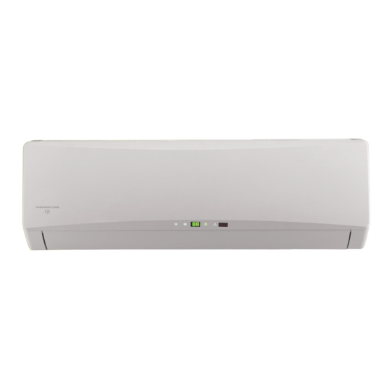
Summary and features Summary and features Indoor Unit GWH18MC-D3DNA3A GWH24MD-D3DNA3A Outdoor Unit GWH18MC-D3DNA1A/O GWH24MD-D3DNA1A/O Remote control window YB1FAF... -
Page 4: Safety Precautions
Safety Precautions 1.Safety Precautions Important! or rubbish. The unit should be installed according to the instructions This air conditioning system meets strict safety and in order to minimize the risk of damage from earthquakes, operating standards. As the installer or service person, typhoons or strong winds. -
Page 5: Unit Specifications
Specifications Specifications 2.1 Unit Specifications Model GWH18MC-D3DNA3A Product Code CB171N0040 COOLING HEATING Function Rated Voltage 208-230V~ Frequency(Hz) 60Hz 5275 7325 Total Capacity (W) Standard (Low~High) ( 1750~6550 ) ( 1200~7325 ) 18000 25000 Total Capacity (Btu/h) Standard (Low~High) ( 6000~22350 )... - Page 6 Specifications GWH18MC-D3DNA1A/O Model of Outdoor Unit China Resources (Shenyang) Sanyo Compressor CO.,LTD Manufacturer/trademark Compressor Model C-6RZ146H1A Compressor Type Twin rotary compressor L.R.A. (A) Compressor RLA(A) Compressor Power Input(W) 1640 Overload Protector 1NT11L-3979 Throttling Method Electric expand valve Starting Method Transducer starting Working Temp Range ( ℃...
- Page 7 Specifications HEATING 6300 7618 Total Capacity (W) Standard (Low~High) ( 2812~7325 ) ( 1260~7618 ) 21500 26000 Total Capacity (Btu/h) Standard (Low~High) ( 9600~25000 ) ( 4300~26000 ) 1790 2750 Power Input (W) Standard (Low~High) ( 500~2650 ) ( 400~2750 ) 950/800/700/600 Air Flow Volume (m /h) (SH/H/M/L)
- Page 8 Specifications GWH24MD-D3DNA1A/O Model of Outdoor Unit CB190W0140 Product Code China Resources (Shenyang) Compressor Sanyo CO.,LTD Manufacturer/trademark Compressor Model C-6RZ146H1A Compressor Type Twin rotary compressor L.R.A. (A) Compressor RLA(A) Compressor Power Input(W) 1640 Overload Protector 1NT11L-3979 Electric expand valve Throttling Method Starting Method Transducer starting Working Temp Range ( ℃...
-
Page 9: Operation Characteristic Curve
Specifications 2.2 Operation Characteristic Curve GWC18MC-D3DNA3A GWH18MC-D3DNA3A Cooling Heating 220V 220V • Conditions Indoor : DB26.7˚C/WB19.4˚C Outdoor : DB35˚C/WB23.9˚C Indoor air flow : Turbo Pipe length : 7.6m 230V 230V 240V • Conditions 240V Indoor : DB21.1˚C/WB15.6˚C Outdoor : DB8.33˚C/WB6.11˚C... -
Page 10: Capacity Variation Ratio According To Temperature
Specifications 2.3 Capacity Variation Ratio According to Temperature Cooling Heating • Conditions • Conditions Indoor : DB26.7˚C/WB19.4˚C Indoor : DB21.1˚C/WB15.6˚C Indoor air flow : Turbo Indoor air flow : Turbo Pipe length : 7.6m Pipe length : 7.6m –15 –10 –5 Outdoor temp. -
Page 11: Noise Criteria Curve Tables For Both Models
Specifications 2.5 Noise criteria curve tables for both models Indoor side noise when blowing Outdoor side noise Middle High Super High Indoor fan motor rotating speed Compressor frequency/Hz... -
Page 12: Indoor Unit
Constrction views 3. Construction Views 3.1 Indoor Unit Air inlet Tube exit Ceiling Left Right MODEL W( ) H( ) D( ) 1008... -
Page 13: Outdoor Unit
Constrction views 3.2 Outdoor Unit 1 8 K Bolt Wrench... - Page 14 Constrction views 2 4 K 1000 Bolt Wrench...
-
Page 15: Part 4 Refrigerant System Diagram
Refrigerant System Diagram 4. Refrigerant System Diagram Cooling & Heating Models Heat exchanger 3-Way ( INDOOR ) valve Muffler 2-Way valve 4-Way valve Strainer Expansion valve Heat exchanger Strainer ( OUTDOOR ) Strainer Cooling Heating... -
Page 16: Electrical Wiring
Schematic Diagram 5. Schematic Diagram 5.1 Electrical wiring Models GWH18MC-D3DNA3A GWH24MD-D3DNA3A These circuit diagrams are subject to change without notice, please refer to the one supplied with the unit. -
Page 17: Printed Circuit Board
Schematic Diagram 5.2 Printed Circuit Board TOP VIEW BOTTOM VIEW... - Page 18 Schematic Diagram TOP VIEW BOTTOM VIEW...
-
Page 19: Description Of Each Control Operation
Function and Control 6.3 DESCRIPTION OF EACH CONTROL OPERATION 1.Basic function of system 1 Cooling mode 1.Under this mode, fan motor, swing will work under setting status, the temp. range is 16-30 (61-86 Fahrenheit scale) 2.Outdoor unit malfunction or unit stop running, indoor unit will keep original running status, malfunction displayed. 3.When 0 (Tset- Tamb.), if indoor fan motor is high speed, that the fanmotorist running in middle s peed, the middle speedor low speedwill be maintained;(this condition shouldbeexecuted when compressor sta r t up);... - Page 20 Function and Control 2. Display state of indoor indicators (1) State of indoor display board 1. When the unit is powered on, all patterns will be displayed and then only power indicator is on. When the unit is turned on with a remote controller, the operating indicator is on and operation mode which is set currently is displayed.
- Page 21 Function and Control (4) Sleep function In this mode, the unit will select the suitable sleep curve to run according to the different setting temperature. (5) Timing function The main board integrates general timing and moment timing. Such two timing functions can be selected through a remote controller on which different functions are arranged.
-
Page 22: Outdoor Units
Function and Control (3) Protecting Treatments of Thermo-bulb: 1.When the thermo-bulb is detected to be short-circuited continuously for 30 seconds: It is regarded that the temperature detected by the thermo-bulb is over-high (or unlimited), then the whole machine will exert corresponding safety stops according to the over-high temperature sensed by the thermo-bulb, and display corresponding temperature safety stops and faults of the thermo-bulb simultaneously. -
Page 23: Special Functions
Function and Control (2) Dehumidifying Mode 1. Conditions and processes of dehumidifying operations: Same as the cooling mode; 2. The temperature setting range is: 16~30 ; (3) Air-supplying Mode 1. The compressor, outdoor fans and four-way valves are switched off; 2. - Page 24 Function and Control (3) 4-way valve control 1. The 4-way valve control under the modes of Cooling, dehumidification and supplying air: closing; 2. The status of 4-way valve control under the heating mode: getting power; (1) 4-way valve power control under heating mode a.
- Page 25 Function and Control 5. Power turn-off: If the ≤T , then Cooling overload protects machine stopping; If T Cooling overload power turn-off temperature outer pipe outer and the compressor has been stopped working for 3 minutes, the pipe Cooling overload frequency-limited temperature machine should be allowed to operate.
- Page 26 Function and Control 5. Power turn-off: If the ≤T , you should discharge to protect machine stopping; If T Power turn-off temperature during discharging Discharge and the compressor has been stopped for 3 minutes, the machine Discharge Limited frequency temperature during discharging should be allowed to operate.
- Page 27 Function and Control ≤T , you should frequency reducing temperature at normal speed of module Module frequency reducing temperature at high speed of module adjust the compressor frequency by reducing 8Hz/90s till the lower limit; After it was running 90s at the lower limit, ≤T , you should stop the machine for module overheating frequency reducing temperature at normal speed of module...
- Page 28 Function and Control 1.Over-High Voltage Protection for DC Bus: If it found the DC bus voltage U , turn off PFC and stop the compressor at once, and it DC Jiekuangchun Protection] shall show the DC over-high voltage failure; it should clear out the failure when the voltage dropped to U and the compressor stopped for 3 min.
-
Page 29: Installation Manual
Installation Manual 7. Installation Manual Installation Installation Important Notices 1. The unit installation work must be done by qualified personnel according to the local rules and this manual 2. Before installating, please contact with local authorized maintenance center, if unit is not installed by the authorized maintenance center, the malfunction may not solved due to discommodious contacts 3. - Page 30 Installation Manual Safety Requirements For Electric Appliances 1. The power supply should be used the rated voltage and AC exclusive circuit, the power cable diameter should be satisfied. 2. Don't drag the power cable emphatically. It should be reliably earthed, and it should be connected to the special earth device, the installation work should be operated by the professional.
- Page 31 Installation Manual Install the rear panel 1.Always mount the rear panel horizontally. Due to the water tray of indoor unit has been adopted the both-way drainage design, the outlet of water tray should be adjusted slightly down when installing, that is taking the outlet of the water tray as the center of a circle, the included angle between the evaporator and level should be 0 or more, that is good for condensing water drainage.
- Page 32 Installation Manual NOTE: When connecting the electric wire if the wire length is not enough, please contact with the authorized service shop to buy a exclusive electric wire that is long enough and the joint on the wire are not allowed. The electric wiring must be correctly connected, wrong connection may cause spare parts ●...
-
Page 33: Installation Of Outdoor Unit
Installation Manual Installation of Outdoor Unit Electric wiring Disassemble the handle on the outdoor unit right side plate. Terminal block of outdoor unit Take off cord anchorage. Connect and fix power connect cord (for cooling and heating unit,connect and fix power connect cord and signal control wire)to terminal block. -
Page 34: Exploded Views And Parts List
Exploded Views and Parts list 8. Exploded Views and Parts List 230V 18K R410A Indoor Unit... - Page 35 Exploded Views and Parts list Product Code Description GWH18MC-D3DNA3A/I Product Code CB171N0040 t l i c i l Ambient Temperature Sensor 390000451 The above data are subject to be changed without notice.
- Page 36 Exploded Views and Parts list 230V 24K R410A Indoor Unit...
- Page 37 Exploded Views and Parts list Product Code Description GWH24MD-D3DNA3A/I Product Code CB171N0060 t l i Mesh enclosure (air out c i l 390000451 Ambient Temperature Sensor The above data are subject to be changed without notice.
- Page 38 Exploded Views and Parts list 230V 18K R410A Outdoor Unit...
- Page 39 Exploded Views and Parts list Part Code Description GWH18MC-D3DNA1A/O CB190W0120 Product Code Fan Motor 1501506302 Electric box (fireproofing) 01413148 Terminal Board 42010255 Capacitor CBB61 ( Fan ) 33010010 Electric Box 20113008 Radiator 49010008 Main Board 30138187 Electric Box Cover Sub-Assy 02603217 Electric Box Assy 0260306603...
- Page 40 Exploded Views and Parts list 230V 24K R410A Outdoor Unit...
- Page 41 Exploded Views and Parts list Part Code Description GWH24MD-D3DNA1A/O CB190W0140 Product Code Fan Motor 1501506205 Electric box (fireproofing) 01413426 Capacitor CBB61 33010011 Electric Box 20113008 Radiator 49010008 Main Board 30138189 Electric Box Cover Sub-Assy 02603217 Electric Box Assy 0260306609 Terminal Board Support Sub-Assy 01715016 Terminal Board 42010255...
-
Page 42: Malfunction Analysis
Troubleshooting 9. Troubleshooting Malfunction Analysis Note: When replacing the controller, make sure insert the wire jumper into the new controller, otherwise the unit will display C5 The breaker trips at once when it Measure insulation resistance to ground to see if there is any leakage. - Page 43 Troubleshooting Improper set of temperature Adjust set temperature If cooling (heating) load is Check the forecasted load of cooling (heating) proper heck and fill the leakage, then The refrigerant has leakage or is vacuumize it and supplement the re- insufficient frigerant as required Leakage between the high pres- Replace the compressor...
- Page 44 Troubleshooting The indoor fan motor is burned or breaks or Replace the fan motor or the defective part. has the heat protector malfunction. The built-in heat protector of the motor breaks Replace the fan motor frequently because the motor is The fan does not abnormal.
- Page 45 Troubleshooting Controller malfunction (IC 2003 broken,creepage of parallel Change c ontroller capacitor of relay loop,re lay is broken etc.) In cool, heat mode,the outdoor unit a nd Correctly wire according to the drawing Wire loose or wrong connection compressor will not run. Improper setting of temperature Adjust setting temp.
- Page 46 Troubleshooting Malfunctions NOTE: <Discharging method> Ω...
-
Page 47: Error Code List
Troubleshooting 9.2 Error Code Discharging Position: Confirmation 1 Confirmation of Power Supply Confirm that the power breaker operates(ON) normally; (2)Confirmation of Power Voltage Confirm that power voltage is AC 220–230–240 ±10%. If power voltage is not in this range, the unit may not operate normally. - Page 48 Troubleshooting □ ■ □ □ □ □ ■ □ ■ ■ □ □ ■ □ □ □ □ □ ■ □ ■ ■ □ ■ ■ ■ □ □ □ ■ □...
- Page 49 Troubleshooting Fan motor works. is too high Blink 11 If higher than 265VAC, Heating: all will stop times please cut off the power supply and restart until back to normal 2. If input voltage is normal, testing the voltage of electrolytic capacitor on AP1 after turn on the unit.
- Page 50 Troubleshooting Cooling, dehumidifying; Off 3s Power voltage compressor will stop, DC Bus voltage □ ■ ■ ■ blink dips indoor fan motor works. is not staable 20 times Heating: all will stop 1.Check the Input voltage if the Cooling, dehumidifying; Voltageis lower than 150VAC, restart Low DC Bus voltage Off 3s...
-
Page 51: Troubleshooting
Troubleshooting Troubleshooting (1) Capacitor cha ge fault (Fault with outdoor unit) (AP1 below refers to the out door control panel) Main Check Points: Use AC voltmeter to check if the voltage between terminal L and N on the wiring board is within 210VAC~240VAC. If the reactor (L) is correctly connected? If the connection is loose or fallen? If the reactor (L) is damaged? Fault diagnosis process: Turn on the unit... - Page 52 Troubleshooting Cooling, dehumidifying; Off 3s Power voltage compressor will stop, DC Bus voltage □ ■ ■ ■ blink dips indoor fan motor works. is not staable 20 times Heating: all will stop 1.Check the Input voltage if the Cooling, dehumidifying; Voltageis lower than 150VAC, restart Low DC Bus voltage Off 3s...
- Page 53 Troubleshooting Energize and switch on Use AC voltmeter If the voltage Check the supply to measure the IPM protection between terminal L voltage and voltage between occurs after the and N on wiring machine has run for terminal L and N restore it to board XT is within a period of time?
-
Page 54: Outdoor Unit
Troubleshooting High temperature and overload protection diagnosis (AP1 hereina fter refers outdoor unit) to the control board of the Mainly detect: ● Is outdoor ambient temperature in normal range? ● Are the outdoor and indoor fans operating normally? ● Is the heat dissipation environment inside and outside the unit is good? Overheat and high temperature protection Normal protection, please operate it after the... - Page 55 Troubleshooting (4) Start-up failure (following AP1 for outdoor unit control board) Mainly detect: Whether the compressor wiring is connected correct? Is time for compressor stopping enough? Is compressor broken? Power on the unit Is stop time of the compressor Restart it up after 3 minutes longer than 3 minutes? Does startup fail? Are the wires for the compressor connected...
- Page 56 Troubleshooting (5) Out of step diagnosis for the compressor (AP1 hereinafter refers to the control board of the outdoor unit) Mainly detect: Whether the system pressure is too high? Whether the input voltage is too low? Out of step occurs in Out of step occurs once the operation unit is powered on.
-
Page 57: Unit Control Board
Troubleshooting (6)Overload and air exhaust malfunction diagnosis (following AP1 for outdoor unit unit control board) Mainly detect: Wether the PMV is connected well or not? Is PMV damaged? Is refrigerant leaked? 20 minutes after the complete unit is powered off Is the terminal FA for the Connect the wires correctly... - Page 58 Troubleshooting 7 Power factor correct or (PFC) fault (a fault of outdoor unit) (AP1 hereinafter refers to the control board of the outdoor unit) Mainly detect: Check if the reactor (L) of the outdoor unit and the PFC capacitor are broken The failure diagnosis process is as follows: Start Check wiring of the...
- Page 59 Troubleshooting (8) Communication malfunction: (following AP1 for outdoor unit control board) Mainly detect: Detect the indoor and outdoor units connection wire and indoor and outdoor units inside wiring is connect well or not, if is there any damage? Is there any damage for the indoor unit mainboard communication circuit? Is communication circuit damaged? The flow chart for malfunction detect: Start Did the equipment operate...
- Page 60 Troubleshooting (9) Flow chart for outdoor communitcation circuit detecting: Start Measure voltage at the Test 10 position as shown in the diagram with a voltmeter Value jumping Measure voltage at the Test 15 position as shown in the diagram with a voltmeter Value jumping Fault with outdoor unit...
- Page 61 Troubleshooting Appendix 1: form for indoor/outdoor unit's ambient sensor numerical value of resistance Temp. Resistance Temp. Resistance Temp. Resistance Temp. Resistance...
- Page 62 Troubleshooting Appendix 2: form for indoor/outdoor unit's tube temperature sensor numerical value of resistance Temp. Resistance Temp. Resistance Temp. Resistance Temp. Resistance...
- Page 63 Troubleshooting Appendix 3: form for indoor/outdoor unit's air exhaust temperature sensor numerical value of resistance Temp. Resistance Temp. Resistance Temp. Resistance Temp. Resistance...
-
Page 64: Removal Procedure Of Indoor Unit
Removal Procedure 10. Removal Procedure 10.1 Removal Procedure of Indoor Unit 1 Disassemble Panel Open the panel, pull the panel outward along the groove and then remove the panel. Twist off the screws on the wiring cover plate, separate the terminals and the remove the wiring cover plate. panel wiring cover plate 2. - Page 65 Removal Procedure 4. Disassemble front case Open the screw covers and twist off the screws used for fixing the panel sub-assy, then remove the front case. front case 5. Disassemble electric box cover Twist off the screws on electric box cover, take out the temperature sensor and then remove the electric box.
- Page 66 Removal Procedure 7. Disassemble evaporator Twist off the screws used for fixing the pipe-pressing plate and then remove the pipe-pressing plate. Twist off the screws at the right and left sides of evaporator, take out the evaporator by hand and let the clasps of end plate on evaporator come out of the groove.
- Page 67 8. Disassemble motor Twist off the screws used for fixing the press plate of generator and then remove the motor. screw...
-
Page 68: Removal Procedure Of Outdoor Unit
Removal Procedure 10.2 Removal Procedure of Outdoor Unit 1. Disassemble top cover Twist off the fastening screw used for fixing the handle, pull it downward and then remove the handle. Twist off the screws around the top cover, pull it top cover upward and then remove the top cover. - Page 69 Removal Procedure 4. Disassemble axial flow blade Loosen the tight nut with spanner and remove the nuts, spring washer, plain washer, then remove the axial flow blade forcibly. clamp nut axial flow blade 5. Disassemble motor and motor support motor support Twist off the clamping screws, take out the motor, twist off the screws used for fixing the motor support , pull it upward and then remove the motor support.
- Page 70 Removal Procedure liquid valve 7.Disassemble the gas valve and liquid valve bolt Twist off the screws used for fixing the gas valve and liquid valve, unsolder the spot weld between gas valve and return-air pipe and then remove the gas valve and gas valve liquid valve.
- Page 71 Removal Procedure 10.3 Removal Procedure of Outdoor Unit 1. Disassemble top cover, front side panel Twist off the clamping screws used for fixing the handle with screwdriver, pull it downward forcibly and then remove the handle. Twist off the screws around the top cover, pull it top cover upward and then remove the top cover.
- Page 72 Removal Procedure 4. Disassemble axial flow blade Loosen the clamp nut with spanner, take out nuts, spring washer, plain washer and then remove the axial flow blade forcibly. axial flow blade clamp nut motor support 5. Disassemble motor and motor support Twist off the fixing screws and then take out the motor.
- Page 73 Removal Procedure 7. Disassemble the gas valve and liquid valve gas valve Twist off the screws used for the gas valve and liquid valve, unsolder the spot weld between gas valve and bolt return-air pipe and then remove the gas valve and liquid valve.
Need help?
Do you have a question about the GWH18MC-D3DNA3A and is the answer not in the manual?
Questions and answers