
Related Manuals for SMART M685i6


Summary of Contents for SMART M685i6
- Page 1 SMART Board® M600i6 Interactive whiteboard systems Configuration and user’s guide For models M680i6 and M685i6...
- Page 2 © 2013 SMART Technologies ULC. All rights reserved. No part of this publication may be reproduced, transmitted, transcribed, stored in a retrieval system or translated into any language in any form by any means without the prior written consent of SMART Technologies ULC. Information in this manual is subject to change without notice and does not represent a commitment on the part of SMART.
-
Page 3: Important Information
Failure to follow the installation instructions shipped with your SMART product could result in personal injury and damage to the product. To reduce the risk of fire or electric shock, do not expose the SMART product to rain or moisture. - Page 4 I M P O R T A N T I N F O R M A T I O N Two people are required to mount your SMART product because it may be too heavy for one person to safely maneuver.
-
Page 5: Other Precautions
I M P O R T A N T I N F O R M A T I O N Using your SMART product near a TV or radio could cause interference to the images or sound. If this happens, move the TV or radio away from the projector. -
Page 6: Environmental Requirements
I M P O R T A N T I N F O R M A T I O N Environmental requirements Before you install your SMART Board M600 interactive whiteboard system, review the following environmental requirements. Environmental Parameter requirement Operating temperature 41°F to 95°F (5°C to 35°C) from 0' to 6000' (0 m to 1800 m) -
Page 7: Table Of Contents
Contents Important information Safety warnings, cautions and important information Environmental requirements Chapter 1: About your interactive whiteboard system SMART Board M600i6 interactive whiteboard system features Included accessories Chapter 2: Installing your interactive whiteboard system Choosing a location Choosing a height Securing the projector to the boom... - Page 8 C O N T E N T S Projector programming commands Appendix C: Integrating other devices Video format Connecting peripheral sources and outputs Appendix D: Remote control code definitions Appendix E: Hardware environmental compliance Waste Electrical and Electronic Equipment and Battery regulations (WEEE and Battery Directives) Batteries Mercury...
-
Page 9: Chapter 1: About Your Interactive Whiteboard System
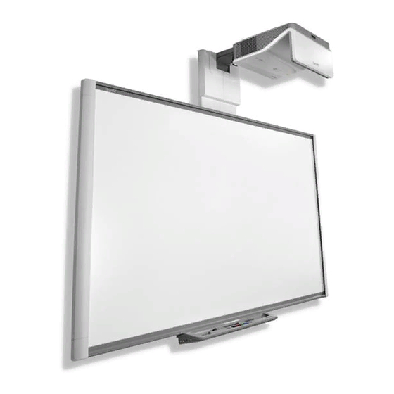
Included accessories Remote control Pens Optional accessories Your SMART Board M600i6 interactive whiteboard system combines the following components: SMART Board M600 series interactive whiteboard Wall-mounted, short-throw SMART UF70 or SMART UF70w projector Accessories and optional equipment This chapter describes the features of your interactive whiteboard and provides information about product parts and accessories. -
Page 10: Smart Board M600I6 Interactive Whiteboard System Features
DVD/Blu-ray™ players, VCRs, document cameras and digital cameras, and can project media from these sources onto the interactive screen. When you use SMART software with your SMART Board M600i6 interactive whiteboard system, you can write or draw over the projected computer image in digital ink using a pen tray pen or your finger, and then save these notes to a .notebook file or directly into any Ink Aware application. - Page 11 WXGA, QVGA, VGA, SVGA, XGA, SXGA, SXGA+ and UXGA video format compatibility Native 1024 × 768 resolution (SMART UF70 projector) Native 1280 × 800 resolution (SMART UF70w projector in 16:10 aspect ratio mode) Remote management via a serial RS-232 interface, web page or SNMP...
-
Page 12: Included Accessories
Optional accessories You can add a variety of accessories to your interactive whiteboard to best meet your specific needs. Purchase these items from your authorized SMART reseller. For more information on accessories, go to smarttech.com/accessories. smarttech.com/kb/170549... -
Page 13: Chapter 2: Installing Your Interactive Whiteboard System
Installing SMART software I M P O R T A N T Use the SMART Board M600i6 interactive whiteboard system installation guide (smarttech.com/kb/170555) to install your interactive whiteboard and projector. This chapter provides additional considerations and details for installing your interactive whiteboard system. -
Page 14: Choosing A Location
You should consider the general height of your user community when you choose a location for your interactive whiteboard. Securing the projector to the boom To learn how to secure the SMART UF70 or SMART UF70w projector to the boom, see the included SMART Board M600i6 interactive whiteboard system installation guide (smarttech.com/kb/170555). smarttech.com/kb/170549... -
Page 15: Routing The Cables
Download SMART software from smarttech.com/software. These web pages list the minimum hardware requirements for each software version. If SMART software is already installed on your computer, take this opportunity to upgrade your software to ensure compatibility. -
Page 17: Chapter 3: Using Your Interactive Whiteboard System
Chapter 3 Using your interactive whiteboard system Using your projector Using your remote control Replacing the remote control battery Using the remote control buttons Adjusting projector settings Focusing the image Adjusting the image Projector connection diagram Using your interactive whiteboard This chapter describes the basic operation of your interactive whiteboard system and explains how to set up your remote control, retrieve system information, access the projector’s image adjustment options and integrate your interactive whiteboard system with peripheral devices. -
Page 18: Replacing The Remote Control Battery
C H A P T E R 3 Using your interactive whiteboard system Replacing the remote control battery Follow this procedure to replace the remote control battery. W A R N I N G Reduce the risk associated with a leaking battery in the projector’s remote control by following these practices: Use only the specified CR2025 coin-cell battery. -
Page 19: Using The Remote Control Buttons
C H A P T E R 3 Using your interactive whiteboard system Using the remote control buttons The projector remote control enables you to access on-screen menus and change projector settings. Use the Power button on the remote control to put the projector into Standby mode or to turn it on. You can also use the Input button on the remote control to switch sources on the projector. -
Page 20: Adjusting Projector Settings
Keep your remote control in a safe place because there is no other way to access menu options. Setting Notes Image Adjustment menu Display Mode Indicates the projector’s display The default is SMART Presentation. output (SMART Presentation, Bright Room, Dark Room, sRGB and User). Brightness Adjusts projector brightness The default is 50. - Page 21 V-Position Moves the vertical position of Don’t adjust this setting unless you’re advised the source video up or down to by SMART Support. from -5 to 5 (relative to the Apply this setting only after you make all boom projected image).
- Page 22 C H A P T E R 3 Using your interactive whiteboard system Setting Notes Projector Functions menu Auto Signal Enables or disables signal The default is off. Detect searching of input connectors. Select On to have the projector continuously switch inputs until it finds an active video source.
- Page 23 Startup Screen, Preview displayed. Startup Screen), or Image SMART displays the default SMART logo on a Alignment Screen. blue background. Capture User Startup Screen closes the on- screen display menu and captures the entire projected image.
- Page 24 C H A P T E R 3 Using your interactive whiteboard system Setting Notes DHCP Displays the status of the The default is on. network’s Dynamic Host On enables a DHCP server on the network to Configuration Protocol (DHCP) automatically assign an IP address to the as On or Off.
- Page 25 C H A P T E R 3 Using your interactive whiteboard system Setting Notes Projector Name Displays the projector’s name You can set the projector’s name using the as set by an administrator remote management features (see Remotely (maximum 12 characters). managing your system through a network interface on page 45 and Remotely managing your system through an RS-232 serial...
-
Page 26: Focusing The Image
C H A P T E R 3 Using your interactive whiteboard system Setting Notes Firmware Displays the projector’s digital Version display processor (DDP) firmware version in x.x.x.x format. MPU Version Displays the projector microprocessor unit (MPU) firmware version in x.x.x.x format. -
Page 27: Adjusting The Image
Using your interactive whiteboard system Adjusting the image Refer to these notes when adjusting the projected image, as described in the included SMART Board M600i6 interactive whiteboard system installation guide (smarttech.com/kb/170555). While adjusting the projected image size, shape and location, use the projector’s default background so that you can see the full projected image clearly. - Page 28 C H A P T E R 3 Using your interactive whiteboard system 11 12 13 14 Connector Connect to: Power Mains power supply 7-pin mini-DIN [Not used] 4-pin power mini-DIN 5V/2A output [Not used] HDMI input High-definition video and audio source (not included) DB15F (DE-15F) RGB video input (VGA 1) Primary computer (not included)
-
Page 29: Using Your Interactive Whiteboard
Refer to the SMART Board M600i6 interactive whiteboard user's guide (smarttech.com/kb/170410) for in-depth information on using your interactive whiteboard and its features. When you connect your SMART Board interactive whiteboard to a computer with SMART software, you can access the full capabilities of your interactive whiteboard. -
Page 31: Chapter 4: Maintaining Your Interactive Whiteboard System
For information on maintaining your interactive whiteboard, see the SMART Board M600 interactive whiteboard installation guide (smarttech.com/kb/170555). With proper care, your SMART Board interactive whiteboard will provide years of trouble-free service. Preventing damage to your interactive whiteboard Although the surface of your interactive whiteboard is very durable, take the following precautions to prevent damage. -
Page 32: Cleaning The Projector
C H A P T E R 4 Maintaining your interactive whiteboard system Don’t use abrasive erasers or harsh chemicals to clean your product. The digital cameras located in the corners of the frame are protected from dust and dirt by windows. -
Page 33: Focusing And Adjusting The Projector Image
C H A P T E R 4 Maintaining your interactive whiteboard system Do not spray cleaners, solvents or compressed air directly on the projector. Do not use spray cleaners or solvents near any part of the projector because they can damage or stain the unit. Spraying the system could spread a chemical mist on some of the projector’s components and lamp, resulting in damage and poor image quality. -
Page 34: Replacing The Projector Lamp
Thoroughly clean the area around the projector, and discard any edible items placed in that area because they could be contaminated. Call your authorized SMART reseller for instructions. Do not attempt to replace the lamp. Replacing the lamp module in a wall-mounted projector can result in a fall or injury. Use caution when climbing a ladder, and consider removing the projector from the wall-mounting bracket to replace the lamp module. - Page 35 Wear protective eyewear while changing the lamp module. Failure to do so can cause injuries including loss of eyesight if the lamp shatters or bursts. Use only replacement lamp modules approved by SMART Technologies. Contact your authorized SMART reseller for replacement parts.
- Page 36 C H A P T E R 4 Maintaining your interactive whiteboard system 5. Use a Phillips screwdriver to loosen the two captive screws from the bottom of the lamp module and gently remove the lamp module. N O T E Don’t try to remove these screws.
-
Page 37: Resetting The Lamp Hours
C H A P T E R 4 Maintaining your interactive whiteboard system 4. Replace the lamp cover. 5. Connect the power cable to the wall outlet. 6. Press the Power button once on the remote control to confirm that the projector is operating and that the lamp module is correctly installed. - Page 38 You’re unable to reset the Display Hour value because it’s the running total of hours the projector has been in use. 3. Press the Menu button on the remote control. The SMART UF70 Settings menu appears. 4. Select to confirm that Lamp Hour is reset to zero.
-
Page 39: Chapter 5: Troubleshooting Your Interactive Whiteboard System
Chapter 5 Troubleshooting your interactive whiteboard system Before you start Locating status lights Locating serial numbers Determining you interactive whiteboard system’s status Resolving interactive whiteboard issues Resolving operation issues Resolving projector issues Resolving projector errors Your projector stops responding The “Projector Overheated”, “Fan Failure”, “Lamp Failure” or “Color Wheel Failure” message appears The “Lamp Failure”... -
Page 40: Before You Start
Locating serial numbers The SMART Board M600 interactive whiteboard serial number is located on the lower-right edge of the frame, as well as on the back of the interactive whiteboard. For more information, see the SMART Board M600 series interactive whiteboard user’s guide (smarttech.com/kb/170410). -
Page 41: Determining You Interactive Whiteboard System's Status
C H A P T E R 5 Troubleshooting your interactive whiteboard system The SMART UF70 and UF70w projector's serial number is located on the top of the projector. For the locations of serial numbers on other components and accessories, see smarttech.com/support. -
Page 42: Resolving Interactive Whiteboard Issues
Resolving interactive whiteboard issues This section includes information on resolving issues with your interactive whiteboard. For information not covered in this section, see the SMART Board M600 series interactive whiteboard user's guide (smarttech.com/kb/170410). Resolving operation issues To resolve operation issues, complete the following tasks: Confirm that all cables are securely connected to the back of the pen tray, computer and control module. -
Page 43: Resolving Projector Issues
Resolving projector issues Resolving projector errors System administrators can resolve the following projector errors on their own prior to contacting SMART Support. Performing initial troubleshooting on your projector reduces the time of a support call. Your projector stops responding If your projector stops responding, perform the following procedure. -
Page 44: The "Lamp Failure" Message Appears
26. 4. If replacing the lamp module doesn’t resolve the issue, put the projector into Standby mode, disconnect the power cable, and then contact your authorized SMART reseller. The projector Power and Service lights are off If the projector Power and Service lights are both off, one of the following issues is occurring: There was a power outage or a power surge. -
Page 45: Resolving Image Issues
If a video source signal isn’t detected, if it’s out of range of the projector’s support video modes or if the signal is being switched to a different device or input, the projector doesn’t show a source signal and instead displays the SMART logo on a blue screen. smarttech.com/kb/170549... -
Page 46: Partial, Scrolling Or Incorrectly Displayed Image
1. Select Start > Control Panel. 2. Click Display, and then select Adjust resolution. 3. Verify that your display resolution setting is 1024 × 768 (SMART UF70 projector), 1280 × 800 (SMART UF70w projector in 16:10 aspect ratio mode) or 1280 × 720 (SMART UF70w projector in 16:9 aspect ratio mode). -
Page 47: Unstable Or Flickering Image
5. Disconnect the power cable from the power outlet, and then wait at least 60 seconds. 6. Connect the power cable, and then turn on the projector. 7. If the previous steps don’t resolve the issue, contact your authorized SMART reseller. smarttech.com/kb/170549... -
Page 48: Your Image Doesn't Fit The Interactive Whiteboard
C H A P T E R 5 Troubleshooting your interactive whiteboard system Your image doesn’t fit the interactive whiteboard If you’re using a SMART UF70w projector with a wide screen interactive whiteboard, verify that you’re using the correct aspect ratio mode for the interactive whiteboard: Interactive whiteboard Aspect ratio mode SMART Board M685 interactive whiteboard... -
Page 49: Resolving Audio Issues
You must display the source input’s video to play its audio through the connected speakers or audio system. 6. If the previous steps don’t resolve the issue, contact your authorized SMART reseller. Resolving network communication issues If you don’t have network access, perform the following procedure to troubleshoot your system. -
Page 50: Accessing The Service Menu
SNMP agent. 4. If you still don’t have network access, contact your network administrator. If your administrator is unable to resolve the issue, contact your authorized SMART reseller. Accessing the service menu C A U T I O N To prevent tampering or unintentional changes, only system administrators should access the service menu. -
Page 51: Transporting Your Interactive Whiteboard System
This packaging was designed to provide optimal shock and vibration protection. If you no longer have your original packaging, purchase the same packaging directly from your authorized SMART reseller. If you prefer to use your own packaging materials, make sure you adequately protect your unit. Make sure that the projector lens and mirror are protected against any physical contact or pressure which may damage the projector’s optics. -
Page 53: Appendix A: Remotely Managing Your System Through A Network Interface
E-mail alerts Password settings Simple Network Management Protocol (SNMP) This appendix includes detailed instructions on how to remotely manage your SMART Board M600i6 interactive whiteboard system settings through a network interface. Web page management You can access advanced setup features via the projector’s web page. This web page enables you to manage the projector from a remote location using any computer connected to your intranet. -
Page 54: Accessing Web Page Management
1. Start your Internet browser. 2. Type the IP address in the address box, and then press ENTER. The SMART UF70 Projector Settings window appears. 3. Select the menu options in the left pane to access the settings on each page. - Page 55 French or Spanish, depending on television channel or media setup. Display Mode Adjusts the display output to SMART Presentation, Bright Room, Dark Room, sRGB and User modes so you can project images from various sources with consistent color performance: SMART Presentation is recommended for color fidelity.
- Page 56 A P P E N D I X A Remotely managing your system through a network interface Submenu setting Description Color Adjusts the Red, Green, Blue, Cyan, Magenta and Yellow colors on the projector from 0 to 100 to provide custom color and luminance output.
- Page 57 See Video format on page 79 for descriptions of each mode. Startup Screen Sets the type of startup screen to SMART or User. The SMART screen is the default SMART logo on a blue background. The User screen uses the saved picture from the Capture User Startup Screen function.
-
Page 58: Network Settings
A P P E N D I X A Remotely managing your system through a network interface Submenu setting Description HDMI Assigns an alternative name to your HDMI input, which appears when you select the HDMI input. Emergency Alert Turns the on-screen alert broadcast message on or off. When enabled, this message displays over the current projected image. -
Page 59: E-Mail Alerts
A P P E N D I X A Remotely managing your system through a network interface Submenu setting Description Read-Only Community Sets a password that is required for each SNMP get request to the device. N O T E The default for Read-Only Community is public. Read/Write Community Sets a password that is required for each SNMP set request to the device. -
Page 60: Simple Network Management Protocol (Snmp)
Submit. N O T E The projector sends an alert e-mail (SMART Alert) to your e-mail address. Click E-mail Alert Test to confirm that your e-mail address and SMTP server settings are correct by sending a test e-mail (SMART Alert-Test Mail). -
Page 61: Appendix B: Remotely Managing Your System Through An Rs-232 Serial Interface
Field definitions Service Information Command/response definitions Field definitions Unknown command This appendix includes detailed instructions on how to set up your computer or room control system to remotely manage your SMART Board M600i6 interactive whiteboard system settings through an RS-232 serial interface. smarttech.com/kb/170549... -
Page 62: Serial Interface Settings
On projectors with the RS-232 connector labeled Control 9v (rather than Control), pin 1 functions as a +9V DC power source only for use with older model ECPs such as the ones shipped with SMART UF55 projectors. Serial interface settings The serial interface of the projector acts as a Data Communications Equipment (DCE) device and its settings can’t be configured. -
Page 63: Projector Programming Commands
A P P E N D I X B Remotely managing your system through an RS-232 serial interface 2. Connect your computer to the serial connection cable you previously connected to the control panel. 3. Configure your serial interface settings using the values from the table above, and then press ENTER. -
Page 64: Field Definitions
These power states match the power states in confirm off the SMART UF70 and SMART UF70w idle projectosr. Source Application Selection Use these commands to switch between input sources and embedded applications. These commands also control the USB switch for these sources. -
Page 65: Field Definitions
A P P E N D I X B Remotely managing your system through an RS-232 serial interface Field definitions Field Possible values Description A text list of available video source inputs. None current input VGA1 is a non-selectable input and is returned in Composite response to a “get input”... -
Page 66: Video Control
A P P E N D I X B Remotely managing your system through an RS-232 serial interface E X A M P L E > set input=vga1 input = vga1 > set input=next input = composite > get videoinputs videoinputs = vga1, composite, hdmi1 >... - Page 67 A P P E N D I X B Remotely managing your system through an RS-232 serial interface get frequency frequency=[current] set tracking [target] tracking=[current] get tracking tracking=[current] set saturation [target] saturation=[current] get saturation saturation=[current] set tint [target] tint=[current] get tint tint=[current] set sharpness [target] sharpness=[current]...
-
Page 68: Field Definitions
[target] Field definitions Field Possible values Description target displaymode The ranges must match the OSD ranges. = SMART Presentation = Bright room = Dark room = sRGB = User current displaymode The ranges must match the OSD ranges. - Page 69 A P P E N D I X B Remotely managing your system through an RS-232 serial interface Field Possible values Description target tracking The ranges must match the OSD ranges. + val – val = 0 to 31 current tracking Range: 0 to 31 The ranges must match the OSD ranges.
- Page 70 A P P E N D I X B Remotely managing your system through an RS-232 serial interface Field Possible values Description target red The ranges must match the OSD ranges. + val – val = 0 to 100 current red Range: 0 to 100 The ranges must match the OSD ranges.
-
Page 71: Audio Control
A P P E N D I X B Remotely managing your system through an RS-232 serial interface Field Possible values Description target displayhide Set the mode directly or move from one state to normal the next sequentially. frozen muted next Use the above commands to set the property to an absolute value or to adjust the current value. -
Page 72: Command/Response Definitions
A P P E N D I X B Remotely managing your system through an RS-232 serial interface Command/response definitions Command Response Powered off set volume [target] volume=[current] get volume volume=[current] set mute [target] mute=[current] get mute mute=[current] set volumecontrol volumecontrol= [target] [current]... -
Page 73: Network Information
A P P E N D I X B Remotely managing your system through an RS-232 serial interface Field Possible values Description target volumecontrol = on Specifies whether volume control is enabled or = off disabled. target cc = cc1 Closed captioning states = cc2 = off... -
Page 74: Command/Response Definitions
A P P E N D I X B Remotely managing your system through an RS-232 serial interface Command/response definitions Command Response Powered off get netstatus netstatus=[current] set network network=[current] get network network=[current] set dhcp [target] dhcp=[current] get dhcp dhcp=[current] set ipaddr [target] ipaddr=[current] get ipaddr... -
Page 75: System Information
A P P E N D I X B Remotely managing your system through an RS-232 serial interface Field Possible values Description target dhcp Enable/Disable for DHCP Networking Range: 0.0.0.0 to current ipaddr Current IP address (static or dhcp assigned) 255.255.255.255 = Range: 0.0.0.0 to target ipaddr... - Page 76 A P P E N D I X B Remotely managing your system through an RS-232 serial interface Command Response Powered off get highbrightness highbrightness= [current] set autopoweroff autopoweroff=[current] no [target] get autopoweroff set autopoweroff=[current] no zoom [target] set zoom [target] zoom=[current] get zoom zoom=[current]...
- Page 77 A P P E N D I X B Remotely managing your system through an RS-232 serial interface Command Response Powered off get fwvermpu fwvermpu=[current] get serialnum serialnum=[current] get fwverecp fwverecp=[current] set language [target] language=[current] get language language=[current] set groupname [target] groupname=[current] get groupname groupname=[current]...
-
Page 78: Field Definitions
A P P E N D I X B Remotely managing your system through an RS-232 serial interface Command Response Powered off set emergencyalert emergencyalert= [target] [current] get emergencyalert emergencyalert= [current] get signaldetected signaldetected= The response varies depending on the power [current] mode. - Page 79 = ceiling = rear = rear ceiling current projectionmode = front The ranges must match the OSD settings. = ceiling = rear = rear ceiling target startupscreen = smart The ranges must match the OSD settings. = usercapture = preview smarttech.com/kb/170549...
- Page 80 Current resolution of the input. If no signal is 1024x768 detected, “resolution=no signal” appears. … no signal 4:3 for SMART UF70, native aspect ratio Native aspect ratio. DLP resolution of the 16:10 for SMART projector. Returns the actual native aspect ratio UF70w of the projector.
- Page 81 A P P E N D I X B Remotely managing your system through an RS-232 serial interface Field Possible values Description current language Arabic Must match the OSD setting Chinese (Simplified) Chinese (Traditional ) Czech Danish Dutch English Finnish French German Greek...
-
Page 82: Service Information
A P P E N D I X B Remotely managing your system through an RS-232 serial interface Field Possible values Description user string current contactinfo user string current modelnum Must match the OSD setting current videomute Must match the OSD setting. target videomute = on Must match the OSD setting. -
Page 83: Field Definitions
A P P E N D I X B Remotely managing your system through an RS-232 serial interface Command Response Powered off set colorwheelidx colorwheelidx= [target] [current] get colorwheelidx colorwheelidx= [current] get failurelog failurelog=[current] get error# error#=[current] set factoryreset [target] factoryreset=[current] set highspeedfan highspeedfan=[current] no [target]... - Page 84 A P P E N D I X B Remotely managing your system through an RS-232 serial interface Field Possible Values Description current colorwheelidx The ranges must match the OSD ranges. current failurelog normal Projector's error state. The modes are projector overtemp dependent.
-
Page 85: Unknown Command
A P P E N D I X B Remotely managing your system through an RS-232 serial interface Field Possible Values Description A power override forces the projector to remain current poweroverride on when the command is received. This command isn’t persistent and isn’t stored to non- volatile memory (cleared on power cycle). -
Page 87: Appendix C: Integrating Other Devices
SMART UF70 projector SMART UF70w projector Connecting peripheral sources and outputs This appendix provides information on integrating your SMART Board M600i6 interactive whiteboard system with peripheral devices. Video format Your projector has a native video format and various video format compatibility modes. You can change image appearances for certain formats and compatibilities. -
Page 88: Video Format Compatibility
Video format compatibility The following tables list the projectors’ compatible VESA RGB video formats by resolution, which the projector adjusts automatically when you use the aspect ratio commands described in Adjusting projector settings on page 12. SMART UF70 projector Resolution Mode Aspect ratio... -
Page 89: Smart Uf70W Projector
1680x1050 50 16:10 49.974 Letterbox 1680 × 1050 1680x1050 50 16:10 59.954 Letterbox 1920 × 1080 HD 1080 16:9 Letterbox SMART UF70w projector Resolution Mode Aspect Refresh Match Input Match Input ratio rate (Hz) appearance appearance (16:10 aspect (16:9 aspect ratio mode) ratio mode) 720 ×... - Page 90 A P P E N D I X C Integrating other devices Resolution Mode Aspect Refresh Match Input Match Input ratio rate (Hz) appearance appearance (16:10 aspect (16:9 aspect ratio mode) ratio mode) 1152 × 864 SXGA 75 Pillarbox Pillarbox 1280 ×...
-
Page 91: Hd And Sd Signal Format Compatibility
The following tables list the projectors’ high definition (HD) and standard definition (SD) format signal compatibility, which the projector adjusts automatically when you use the aspect ratio commands described in Adjusting projector settings on page 12. SMART UF70 projector Signal format Aspect ratio... -
Page 92: Video System Signal Compatibility
The 16:9 command delivers all video modes with black bands along the top and bottom edges of the screen. The Match Input command might deliver video modes with black bands along the top and bottom edges of the screen, depending on the input resolution. SMART UF70 projector Video mode Aspect ratio... -
Page 93: Connecting Peripheral Sources And Outputs
A P P E N D I X C Integrating other devices Connecting peripheral sources and outputs Follow these instructions if you have a peripheral device to connect to your interactive whiteboard system, such as a DVD/Blu-ray player. N O T E Measure the distance between the projector and the peripheral device you want to connect. -
Page 95: Appendix D: Remote Control Code Definitions
Appendix D Remote control code definitions IR signal format: NEC1 Repeat Vendor code Key code format Byte 1 Byte 2 Byte 3 Byte 4 Input Power ( ) Menu Up ( ) Left ( ) Enter ( ) Right ( ) Down ( ) Hide Volume up ( ) -
Page 97: Appendix E: Hardware Environmental Compliance
Appendix E Hardware environmental compliance SMART Technologies supports global efforts to ensure that electronic equipment is manufactured, sold and disposed of in a safe and environmentally friendly manner. Waste Electrical and Electronic Equipment and Battery regulations (WEEE and Battery Directives) Electrical and electronic equipment and batteries contain substances that can be harmful to the environment and to human health. -
Page 99: Index
Index DNS 50 document cameras 85 dust iv 3.5 mm audio connectors 20 DVD players 85 accessories e-mail alerts 51 included 4 electrostatic discharge iv optional 4 emergency alerts 50 alarms 50 emissions iv aspect ratios 15, 49, 79-81, 83-84 environmental requirements iv audio connections for 20... - Page 100 I N D E X choosing a location 6 Perchlorate material 89 interactive whiteboard peripheral sources 85 about 2 pillarboxing 80-81, 83 indicators and controls of 34 power 20, 46, 55 maintaining 23 projector using 21 about 3 IP address 16, 46, 50 adjusting settings for 12 adjusting the image of 19 cleaning 24...
- Page 101 I N D E X serial number 32 signal loss 37 SMART Board interactive XGA support 80-81 whiteboard See interactive whiteboard SMART UF70 or UF70w projector See projector SMTP 51 zoom 48 SNMP 52 sound See audio startup screen 49 subnet mask 16, 50...
- Page 102 SMART Technologies smarttech.com/support smarttech.com/contactsupport smarttech.com/kb/170549...
Need help?
Do you have a question about the M685i6 and is the answer not in the manual?
Questions and answers