Wacker Neuson GV 5600A Operator's Manual
Hide thumbs
Also See for GV 5600A:
- Repair manual (74 pages) ,
- Operator's manual (62 pages) ,
- Operator's manual (38 pages)

Related Manuals for Wacker Neuson GV 5600A


Summary of Contents for Wacker Neuson GV 5600A
- Page 1 0174920en 0908 Generator GV 5600A CARB OPERATOR’S MANUAL...
-
Page 2: Carbon Monoxide
DANGER CARBON MONOXIDE Using a generator indoors CAN KILL YOU IN MINUTES. Generator exhaust contains carbon monoxide (CO). This is a poison you cannot see or smell. If you can smell the generator exhaust, you are breathing CO. But even if you cannot smell the exhaust, you could be breathing CO. -
Page 3: Table Of Contents
Table of Contents GV 5600A Foreword California Evaporative Emission Control Warranty Statement 6 Safety Information Laws Pertaining to Spark Arresters ............8 Operating Safety ...................9 Operator Safety while using Internal Combustion Engines ....11 Service Safety ..................12 Label Locations ...................13 Safety and Operating Labels ...............14 Operation Determining Power Requirements ............17... - Page 4 GV 5600A Table of Contents Maintenance Engine Maintenance ................28 Periodic Maintenance Schedule ............28 Engine Oil ................... 29 Servicing Air Cleaner ................30 Spark Plug ..................31 Cleaning the Sediment Cup ............... 32 Storage ....................33 Transport .................... 34 Troubleshooting ..................
-
Page 5: Foreword
Foreword This manual provides information and procedures to safely operate and maintain this Wacker Neuson model. For your own safety and protection from injury, carefully read, understand and observe the safety instructions described in this manual. Keep this manual or a copy of it with the machine. If you lose this manual or need an additional copy, please contact Wacker Neuson Corporation. -
Page 6: California Evaporative Emission Control Warranty Statement
This EECS is warranted for two years from the initial date of purchase. If any evaporative emission-related part on your equipment is defective, the part will be repaired or replaced by Wacker Neuson Corporation at no charge to you. The owner shall not be charged for... - Page 7 Corporation cannot deny warranty solely for the lack of receipts. As the portable generator owner, you should however be aware that Wacker Neuson Corporation may deny you warranty coverage if your portable generator or a part has failed due to abuse, neglect, or improper maintenance or unapproved modifications.
-
Page 8: Safety Information
GV 5600A Safety Information Safety Information This manual contains DANGER, WARNING, CAUTION, NOTICE and NOTE callouts which must be followed to reduce the possibility of personal injury, damage to the equipment, or improper service. This is the safety alert symbol. It is used to alert you to potential personal injury hazards. -
Page 9: Operating Safety
Safety Information GV 5600A Operating Safety Using a generator indoors CAN KILL YOU IN MINUTES. Generator exhaust contains carbon monoxide. This is a poison you cannot see or smell. NEVER use this generator inside a home or garage, EVEN IF doors and windows are open. - Page 10 GV 5600A Safety Information 3.2.7 NEVER operate the machine in snow, rain, or standing water. 3.2.8 NEVER allow untrained personnel to operate or service the generator. The generator set should be set up by a certified electrician. 3.2.9 NEVER stand on the machine.
-
Page 11: Operator Safety While Using Internal Combustion Engines
Safety Information GV 5600A Operator Safety while using Internal Combustion Engines Internal combustion engines present special hazards during operation and fueling. Read and follow the warning instructions in the engine owner’s manual and the safety guidelines below. Failure to follow the DANGER warnings and safety standards could result in severe injury or death. -
Page 12: Service Safety
GV 5600A Safety Information Service Safety Poorly maintained equipment can become a safety hazard! In order for the equipment to operate safely and properly over a long period of time, periodic maintenance and occasional repairs are necessary. If WARNING the generator is experiencing problems or is being serviced, attach a “DO NOT START”... -
Page 13: Label Locations
Safety Information GV 5600A Label Locations wc_si000269gb.fm... -
Page 14: Safety And Operating Labels
GV 5600A Safety Information Safety and Operating Labels Wacker Neuson machines use international pictorial labels where needed. These labels are described below: Label Meaning DANGER! No sparks, flames or burning objects near machine. Shut off the engine before refueling. WARNING! - Page 15 Safety Information GV 5600A Label Meaning Open the fuel flow valve. Close the choke. Turn the engine switch to the ON position. Pull the rewind starter. Open the choke. Open main circuit breaker. Turn the engine switch to “OFF”. Close the fuel flow valve.
- Page 16 GV 5600A Safety Information Label Meaning Using a generator indoors CAN KILL YOU IN MINUTES. Generator exhaust contains carbon monoxide. This is a poison you cannot see or smell. NEVER use inside a home or garage, EVEN IF doors and windows are open.
-
Page 17: Operation
Check with your nearest Wacker Neuson Dealer, or contact the manufacturer or dealer of the tool or appliance, with questions regarding its power requirements. -
Page 18: Installation
GV 5600A Operation Installation Place the generator in an area where it will not be exposed to rain, snow, or direct sunlight. Make sure it is positioned on firm, level ground, so it will not slide or shift. Position the engine exhaust away from areas where people may be present. -
Page 19: Generator Derating
Operation GV 5600A Generator Derating All generators are subject to derating for altitude and temperature. Internal combustion engines, unless modified, run less efficiently at higher altitudes due to the reduction of air pressure. This translates into a lack of power and thus reduction in generator output. -
Page 20: Grounding The Generator
GV 5600A Operation Grounding the Generator A ground connection (a) is located on the generator frame. For proper operating safety, this ground terminal must be connected to a good ground source. This ground connection must comply with National Electrical Code standards, and state and local regulations. -
Page 21: Use Of Extension Cords
Operation GV 5600A Use of Extension Cords When a long extension cord is used to connect an appliance or tool to the generator, a voltage loss occurs—the longer the cord, the greater the voltage loss. This results in less voltage being supplied to the appliance or tool and increases the amount of current draw or reduces performance. -
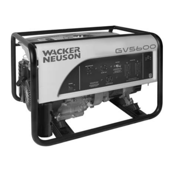
Page 22: Control Panel
GV 5600A Operation Control Panel Ref. Description Ref. Description Engine switch GFI duplex receptacle—125V Auto idle switch GFI test button Twist-lock receptacle—125/250V GFI reset button Main circuit breaker Twist-lock receptacle—125V Voltage Selector Switch (VSS) -
Page 23: Ground Fault Interrupt (Gfi)
Operation GV 5600A Ground Fault Interrupt (GFI) See Graphic: wc_gr003960 Each of the 125V, 20 Amp receptacles (f) is equipped with a ground fault circuit interrupt (GFI). The GFI shuts off power to the receptacle when a ground fault occurs to a piece of equipment attached to the generator. -
Page 24: Voltage Selection
GV 5600A Operation 4.11 Voltage Selection See Graphic: wc_gr003960 The voltage selector switch (VSS) (e) switches the generator output between the single-voltage mode (120V) and the dual-voltage (120/ 240V) mode. In single-voltage mode, the full rated power of the generator is shared between the two 125V GFI duplex receptacles and the 125V twist-lock receptacle. -
Page 25: Before Starting
Operation GV 5600A 4.13 Before Starting 4.13.1 Read and understand the safety and operating labels and instructions at the beginning of this manual. 4.13.2 Inspect the generator for any signs of damage which may affect operation or pose a safety hazard. -
Page 26: To Start
GV 5600A Operation 4.14 To Start Before starting, be sure you read and understand all the safety and operating instructions in this manual. 4.14.1 Disconnect all loads from the generator and place the main breaker in the "OFF" position (a2). -
Page 27: To Stop
Operation GV 5600A 4.15 To Stop 4.15.1 Turn off and disconnect all tools and appliances attached to the generator. 4.15.2 Place the main circuit breaker in the OFF position (a2). 4.15.3 Place the engine switch to OFF (b2). 4.15.4 Close the fuel valve (d2). -
Page 28: Maintenance
GV 5600A Maintenance Maintenance Engine Maintenance The chart below lists basic machine and engine maintenance. Refer to your engine Operator’s Manual for additional information on engine maintenance. Periodic Maintenance Schedule Daily After Every Every Every before first starting 20 hrs. -
Page 29: Engine Oil
Maintenance GV 5600A Engine Oil 5.3.1 Drain the oil while the engine is still warm. 5.3.2 Remove the oil filler plug (a) and the drain plug (b) to drain the oil. Note: In the interests of environmental protection, place a plastic sheet and a container under the machine to collect any liquid that drains off. -
Page 30: Servicing Air Cleaner
GV 5600A Maintenance Servicing Air Cleaner Service the air cleaner frequently to prevent carburetor malfunction. NOTICE: NEVER run the engine without the air cleaner. Severe engine damage will occur. NEVER use gasoline or other types of low flash-point solvents for cleaning the air cleaner. -
Page 31: Spark Plug
Maintenance GV 5600A Spark Plug Clean or replace the spark plug as needed to ensure proper operation. Refer to your engine operator’s manual. The muffler becomes very hot during operation and remains hot for a while after stopping the engine. Do not touch the muffler while it is hot. -
Page 32: Cleaning The Sediment Cup
GV 5600A Maintenance Cleaning the Sediment Cup 5.6.1 Turn the fuel valve off. 5.6.2 Remove the sediment cup (a) and the O-ring (b). 5.6.3 Wash both thoroughly in a nonflammable solvent. Dry and reinstall them. 5.6.4 Turn the fuel valve on and check for leaks. -
Page 33: Storage
Maintenance GV 5600A Storage Before storing the generator for a long period of time: 5.7.1 Close the fuel valve and remove and empty the sediment cup or fuel strainer. 5.7.2 Disconnect the fuel line from the carburetor. Place the open end of the fuel line into a suitable container and open the fuel valve to drain the fuel from the tank. -
Page 34: Transport
GV 5600A Maintenance Transport Let the engine cool before transporting the generator or storing it indoors, to avoid burns or fire hazards. WARNING When transporting the generator: 5.8.1 Turn the engine fuel valve to the OFF position. 5.8.2 Position the generator level to prevent fuel from spilling. -
Page 35: Troubleshooting
Maintenance GV 5600A Troubleshooting Problem / Symptom Reason / Remedy If engine does not start, check • Engine switch is on "Start". that: • Fuel valves under fuel tank and on engine are open. • Fuel tank has fuel. • Choke lever is in correct position. Choke should be closed when starting a cold engine. -
Page 36: Technical Data
GV 5600A GV 5600A Technical Data GV 5600A Technical Data Generator Item No. GV 5600A 0620335 Generator Maximum output 5600 Continuous output 5000 Type Single phase, self-exciting, 2-pole, field rotating AC voltages available Volts 120/240 phase Frequency Power factor cos ø... -
Page 37: Engine
GV 5600A Technical Data GV 5600A Engine Engine Power Rating Net power rating per SAE J1349. Actual power output may vary due to conditions of specific use. Item No. GV 5600A 0620335 Engine Engine make Honda Engine model GX 340 R1 Max. -
Page 38: Electrical Schematic
GV 5600A GV 5600A Technical Data Electrical Schematic... -
Page 39: Schematic Components
GV 5600A Technical Data GV 5600A Schematic Components Ref. Description Ref. Description Ref. Description Generator Control Box Engine Ref. Description Ref. Description Main stator winding Spark plug Secondary winding Slip ring Rotor winding Auto idle unit Automatic voltage regulator Voltage selector switch Main circuit breaker Twist lock receptacle—125/250V... - Page 40 Fax: +49 - (0)89-3 54 02-3 90 Wacker Neuson Corporation · P.O. Box 9007 · Menomonee Falls, WI 53052-9007 · Tel. : (262) 255-0500 · Fax: (262) 255-0550 · Tel. : (800) 770-0957 Wacker Asia Pacific Operations · Skyline Tower, Suite 2303, 23/F · 39 Wang Kwong Road, Kowloon Bay, Hong Kong · Tel. +852 2406 60 32 · Fax: +852 2406 60 21...
Need help?
Do you have a question about the GV 5600A and is the answer not in the manual?
Questions and answers