Avid Technology ISIS 5000 Setup Manual
Hide thumbs
Also See for ISIS 5000:
- Setup manual (181 pages) ,
- Administration manual (193 pages) ,
- Quick start manual (19 pages)
Table of Contents
Advertisement
Quick Links
Advertisement
Table of Contents

Related Manuals for Avid Technology ISIS 5000


Summary of Contents for Avid Technology ISIS 5000
- Page 1 Avid ® ISIS ® 5000 Setup Guide...
-
Page 2: Legal Notices
This document is supplied as a guide for Avid ISIS 5000. Reasonable care has been taken in preparing the information it contains. However, this document may contain omissions, technical inaccuracies, or typographical errors. - Page 3 Permission to use, copy, modify, and distribute this software and its documentation for any purpose and without fee is hereby granted, provided that the above copyright notice appear in all copies and that both that copyright notice and this permission notice appear in supporting documentation.
- Page 4 Windows is either a registered trademark or trademark of Microsoft Corporation in the United States and/or other countries. All other trademarks contained herein are the property of their respective owners. Avid ISIS 5000 Setup Guide • 0130-30339-01 Rev. D • June 2011 • Created 6/30/11...
-
Page 5: Table Of Contents
ISIS 5000 Engine Models........ - Page 6 Securing the Avid ISIS 5000 in a Rack ....... . .
- Page 7 Chapter 4 Installing the Avid ISIS Software ........72 Windows Operating System and Network Settings.
- Page 8 Chapter 6 Avid ISIS Upgrade Guidelines ........116 Health Check.
- Page 9 Using Windows Hyperterminal ........149 Loading the Avid Cisco Configuration .
- Page 10 Appendix A Safety and Regulatory Information ....... 183 Warnings and Cautions..........183 FCC Notice .
-
Page 11: Using This Guide
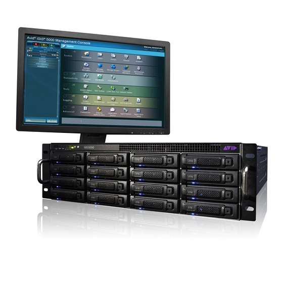
Using This Guide ® ® The Avid ISIS 5000 real-time shared storage system is the foundation for reliable, high-productivity media production. It is designed for media facilities and broadcasters using the industry's most proven real-time storage software technology, delivering stable operation, high performance media access, and class-leading value. -
Page 12: If You Need Help
If You Need Help Symbol or Convention Meaning or Action Courier Bold font identifies text that you type. Courier Bold font Ctrl+key or mouse action Press and hold the first key while you press the last key or perform the mouse action. -
Page 13: Accessing The Online Documentation
The Avid ISIS online documentation contains all the product documentation in PDF format. You can access the documentation in the AvidISISDocumentation folder on the Avid ISIS installer kit. You need to download and install Acrobat Reader on your Avid ISIS 5000 before you can access the PDF documentation. -
Page 14: Avid Isis Overview
RAID controller, Gigabit and 10 Gigabit Ethernet plus redundant power and fans. Up to six Engines are supported in the ISIS 5000, with 2 TB media storage drives can be combined to deliver 192 TB of shared storage. The first ISIS Engine provides System Director and Management Console functionality in addition to media storage. -
Page 15: Avid Isis Hardware
The Windows Product Key Certificate of Authenticity is attached to the top cover of the Avid ISIS enclosure. The Avid ISIS 5000 Engine can be configured as a standalone system that runs the Avid ISIS 5000 System Director software. Up to six Engines can be grouped to created a larger shared storage environment. -
Page 16: Avid Isis Front Panel
Avid ISIS Hardware Avid ISIS Front Panel The Avid ISIS 5000 comes with an Avid bezel that covers the front of the enclosure and can be locked to prevent unauthorized personnel from accessing the buttons and data drives. The following is an illustration of the Avid ISIS enclosure with the front bezel installed. - Page 17 Avid ISIS Hardware Data Drive LED Functions Management Console Drive State Blue LED Red LED Messaging Comments On-line Inactive On solid No Special Status Healthy online drive, no disk I/O On-line Active Activity No Special Status Healthy online drive, with disk I/O Healthy Spare On solid Slow flashing...
-
Page 18: System Front Panel And Leds
Avid ISIS Hardware System Front Panel and LEDs The system has 8 LEDs on the top of the front panel organized into two rows, each row with four LEDs. The first 3 columns of LEDs (6 LEDs) represent activity on each of the six network ports. The top right LED represents system hardware errors. -
Page 19: Drive Array And Slot Locations
Each Engine provides 16 TB in the ISIS 5000-16 and 32 TB in the ISIS 5000-32 of storage with the option to bind up to six Engines for a possible total of 192 TB. Each new installation creates a common slot configuration, once you have a failed drive and use the spare drive, the initial drive configuration of RAID groups and spare drive no longer applies. -
Page 20: Raid Behavior In The Engine
The following illustration shows the shipping configuration of the ISIS 5000-32. The Myricom 10 Gb Ethernet adapter board is optional in the ISIS 5000-16. The Quad Port 1 Gb Ethernet adapter board (not shown) is optional in both the ISIS 5000-16 and ISIS 5000-32. For instructions on installing the optional adapters boards, see “Optional Network Adapter Boards”... -
Page 21: Expansion Slots
® Myricom board PCI-E x16 connector on the ISIS 5000-32 Engine. This is an option board in the ISIS 5000-16. This is a 10-Gb connection for configurations with multiple storage enclosures or for a single 10-Gb client in a direct connect configuration. -
Page 22: System Drives
Avid ISIS Hardware System Drives There are two system drives accessible from the rear of the Avid ISIS enclosure. These two drives are mirrored and if a failure occurs on either one of the system drives, you can pull the failed drive out of the enclosure and install a replacement drive without turning off the Avid ISIS enclosure. -
Page 23: Avid Isis Networks
Real-time media reads and writes are not possible unless the connected clients are running a qualified Avid editing application and have the Avid ISIS client software installed. See the Avid ISIS 5000 ReadMe for a list of supported hardware and Avid editing applications. - Page 24 Avid ISIS Networks The Quad Port 1 Gb and 10 Gb Ethernet adapter boards are options in the ISIS 5000-16 Engine. For instructions on installing the Ethernet adapter boards, see “Optional Network Adapter Boards” on page Avid ISIS 5000 direct connect configurations do not support dual-link client connections or Avid Interplay environments.
-
Page 25: System Director And Switch 1 Gb Connections
Avid ISIS Networks System Director and Switch 1 Gb Connections A single ISIS Engine can connect to a switch using the four Intel Pro 1000 1 Gb Ethernet ports (1, 3, 4, and 6) on the rear of the Engine. When using a single Engine, that Engine must be configured as the System Director. -
Page 26: Engine And Switch 10 Gb Connections
“10 Gb Ethernet S60 Switch Connections” on page 63). The 10 Gb board is an option in the ISIS 5000-16 Engine. For instructions on installing the 10 Gb Ethernet adapter board, see “Optional Network Adapter Boards” on page Avid ISIS Infrastructure — with Optional Storage... -
Page 27: Installation Consideration
Installation Consideration Installation Consideration To set up an Avid ISIS environment you need: • An Avid ISIS Engine • Avid ISIS software If using System Director Resiliency, an Application Key must be installed on both the Active and Standby System Directors. •... - Page 28 • You cannot mix ISIS 5000-32 (2 TB) drives and ISIS 5000-16 (1 TB) drives in the same Engine. •...
-
Page 29: Optional Network Adapter Boards
This chapter provides procedures for adding and replacing network adapter boards in your Avid ISIS 5000. Do not add any hardware if there are any issues with the system. Correct all problems before adding new hardware and making changes to the system. Perform a quick check to verify that the system is in good working order. -
Page 30: Electrostatic Discharge Precautions
Electrostatic Discharge Precautions • The Intel four port 1 Gb Ethernet board does not ship installed in either the ISIS 5000-32 or the ISIS 5000-16 Engines. This optional board is only in direct connect configurations when you want 5 to 8 1 Gb clients connected to the ISIS Engine. For sample configurations see “Direct Connect Clients”... - Page 31 Removing and Installing the System Cover 5. Pull the two pull tabs on the sides of the cover outward and lift the cover off the system. Removing the Top System Cover Front Pull tabs Top cover screws Thumb screws To install the server system cover: 1.
-
Page 32: Installing The Adapter Board
Removing and Installing the System Cover Installing the Adapter Board To install the adapter board: 1. Observe the safety precautions described in “Electrostatic Discharge Precautions” on page 2. Remove the Engine as previously described, see “Removing and Installing the System Cover”... -
Page 33: Myricom 10-Gb Driver And Configuration Settings
After you have installed the Myricom 10-Gb Ethernet adapter board in the Engine and power it on, the Windows Hardware Wizard does not display. The preloaded Avid software already includes a Myricom driver. You do need to update the driver for ISIS 5000 v3.2. For instruction for updating the driver, see “Updating the 10 Gb Myricom Board Driver on Engines”... -
Page 34: Installing The Avid Isis System
The Windows Product Key Certificate of Authenticity is attached to the top of the Engine. The standard Avid ISIS components: • Data drives — Each Engine has sixteen, 1 TB (ISIS 5000-16) or 2 TB (ISIS 5000-32), externally accessible, data drives. •... -
Page 35: Installing Avid Isis Hardware In A Rack
Installing Avid ISIS Hardware in a Rack The Avid ISIS 5000 is designed for 19-inch (483-mm) racks and require three EIA rack units (3U), or 5.25 inches (133.4 mm) of rack space. The rail kit installs into rails that are between 23-inches (584.2-mm) to 31-inches (787.4-mm) inches deep. -
Page 36: Rack-Mount Requirements
Avid ISIS 5000 airflow is from the front of the enclosure to the rear. Make allowances for cooling air to be available to the front panel surface and no restrictions at the rear. -
Page 37: Positioning The Avid Isis Engine In The Rack
The following information helps you decide where to install the Avid ISIS in the rack. To position the Avid ISIS in the rack enclosure: Select a position in the rack where the Avid ISIS is at the proper baseline position. Positioning the Avid ISIS 5000 Rack mounting rail 5/8 in... -
Page 38: Separating The Slide Rails
4. Repeat these steps to separate the second slide rail. Attaching Inner Slide Rails to the Avid ISIS 5000 Attach the inner slide rails that were separated from the outer slide rails to the Avid ISIS 5000. To attach the inner slide rails: 1. -
Page 39: Attaching The Outer Rails To A Square-Hole Rack
Installing Avid ISIS Hardware in a Rack You might find more screws in the rail kit than is needed, and described in this procedure. Attaching the Inner Slide Rails 3. Repeat this procedure to attach the other inner slide rail on the other side of the Engine. Attaching the Outer Rails to a Square-Hole Rack After separating the slide rails as previously described (see “Separating the Slide Rails”... - Page 40 Installing Avid ISIS Hardware in a Rack 2. Slide the square tabs through the holes in the front, vertical rack-mounting rail. Positioning the Outer Slide Rail with the Front Rack-Mounting Rail 3. Push the outer rail towards the outside of the rack, to secure the outer rail in place Insert the Outer Slide Rail to the Front Rack-Mounting Rail 4.
- Page 41 Installing Avid ISIS Hardware in a Rack 5. Secure the rear outer slide rail bracket assembly to the rear mounting rail as you did for the front rack-mounting rail. Securing the Outer Slide Rail to the Rear Rack-Mounting Rail 6. Repeat this procedure to attach the second outer slide rail on the other side of the rack.
-
Page 42: Attaching The Outer Rails To A Round-Hole Rack
Installing Avid ISIS Hardware in a Rack Attaching the Outer Rails to a Round-Hole Rack After separating the slide rails as previously described (see “Separating the Slide Rails” on page 38), perform the following procedure. If your mounting rails have round holes, you first need to clip on the round hole adapter. - Page 43 Installing Avid ISIS Hardware in a Rack 3. Slide the outer slide rail bracket assembly onto the side rack-mounting rail so that the round hole adapter is over the rack rail. You should have someone helping you hold the slide rails level while you are positioning them in the rack.
-
Page 44: Securing The Avid Isis 5000 In A Rack
Engine) are align with the outer slide rails secured to the rack. 2. Push the front of the Avid ISIS 5000 flush against the front mounting rail. The holes in the Avid ISIS Engine front panel align with the holes in the front mounting rail. -
Page 45: Installing The Force10 S25 And S4810 Switches In A Rack
Installing Avid ISIS Hardware in a Rack Installing the Force10 S25 and S4810 Switches in a Rack Make sure you have at least 1U of rack space available prior to installing. The illustrations in this section show the Force10 S25 switch, but the Force10 S4810 switch is rack-mounted in the same way. -
Page 46: Installing The Force10 S60 Switch In A Rack
Installing Avid ISIS Hardware in a Rack 4. From the front of the rack enclosure, secure the switch to the rack with the large screws included with the switch. You can use your own rack hardware if your rack has square holes or unique fasteners. Installing the Force10 S60 Switch in a Rack Make sure you have at least 1U of rack space available prior to installing. - Page 47 Installing Avid ISIS Hardware in a Rack To secure the Force10 switch to the rack enclosure: 1. Attach the rack-mount brackets using the four small flat-head screws on each side. Rack-mount brackets View from rear Screws Rack-mount brackets Power Supply Front 2.
-
Page 48: Installing The Avid Isis Drives
Installing the Avid ISIS Drives Installing the Avid ISIS Drives To install a drive in the Avid ISIS: 1. Locate the data drives that came with your Avid ISIS. 2. Select one drive. 3. Push the drive carrier latch in to release the handle and pull the handle completely open to insert the drive carrier. -
Page 49: Connecting A Keyboard, Monitor, And Mouse
If you do not have a USB splitter cable, plug your keyboard and mouse cables directly into the USB ports on the rear of the Avid ISIS 5000. 4. Insert the other end of the USB splitter cable into a USB connector on the back of the Avid... -
Page 50: Connecting Power Cords
Connecting Power Cords Connecting Power Cords To connect the power cords to the Avid ISIS 5000: 1. Plug two power cords into the back of the Engine and then plug the other ends into power outlets. Avid ISIS Power Connections... -
Page 51: Configuring Considerations
Connecting Clients Directly to the System Director You can connect up to eight clients directly into the Avid ISIS 5000. Each client needs to be configured on a separate subnet. The Intel Pro network port on the ISIS 5000 and the client network port need to be configured with different IP addresses on the same subnet. -
Page 52: System Director 1 Gb Ethernet Connections To The Switch
“Loading the Software” on page System Director 1 Gb Ethernet Connections to the Switch The following instructions describe how to connect the Avid ISIS 5000 to an Ethernet switch using the 1 Gb Ethernet ports. To install the Ethernet switch: 1. - Page 53 3. Attach one end of your Ethernet cable to each of the four outside 1 Gb Ethernet ports on the back of the Avid ISIS 5000. These ports are the Intel Pro network ports and labeled 1, 3, 4, and 6.
-
Page 54: Force10 Ethernet Switch
Ethernet cables to the front of the switch. For a list of currently supported Ethernet switches, see the latest Avid ISIS 5000 ReadMe. Avid recommends you make your network connections between the switch and the Avid ISIS Engine before loading the software. - Page 55 Force10 Ethernet Switch The following sections described the optional module installation for the two supported Force10 switches: • “Force10 S25 Switch Modules” on page 56 • “Force10 S60 Switch Modules” on page 63 Force10 S4810 switches do not support optional modules for stacking.Each port of the S4810 can be configured for 1Gb or 10 Gb connections.
-
Page 56: Force10 S25 Switch Modules
10 Gb Ethernet module or 12 Gb stacking modules. The 10 Gb module provides a 10 Gb Ethernet connection between the Avid ISIS 5000 Engine and the switch. The 12 Gb module is for stacking two Force10 switches, one module is needed in each switch. Modules are ordered separately and can install in either slot on the back of the Force10 switch. - Page 57 Force10 S25 Switch Modules To connect the Avid ISIS 5000 to a 10 Gb Ethernet port on the switch: 1. (If connected) Remove both power cords from the back of the switch. 2. Removed the left blank faceplate cover on the back of the switch by removing the two screws that secure the cover to the switch.
- Page 58 Force10 S25 Switch Modules 7. Insert an SFP+ transceiver into the 10 Gb Ethernet connector in the Avid ISIS Engine. Insert the SFP+ Transceiver into to the 10 Gigabit Ethernet Port on the Engine 8. Connect one end of the LC to LC cable into the transceiver on the rear of the switch. Use a standard duplex LC to LC cable for the 10 Gb connections.For LC to LC cable specifications, see “Supported Cabling”...
-
Page 59: Stacking The Force10 S25 Switches
Force10 S25 Switch Modules 10. (Additional Engines) Attach one end of the 10 Gb Ethernet cable to one of the 10 Gb ports on the back of the switch and the other end to the 10 Gb port on the Avid ISIS Engine. If connecting a third or four Engine configuration, a second 10 Gb module needs to be installed in the Force10 Switch, see “Force10 S25 Switch Modules”... - Page 60 Force10 S25 Switch Modules If using a stacked switch configuration, the 10 Gb connection from the Avid ISIS can be to either switch. To stack Force10 S25 switches: 1. Install a 12 Gb stacking module into the right slot of the Force10 switch, similar to the process described in “Force10 S25 Switch Modules”...
-
Page 61: Connecting Multiple Engines To The Stacked Switch
Force10 S25 Switch Modules Connecting Multiple Engines to the Stacked Switch The Avid ISIS Engine System Director lets you expand your storage capacity by adding an additional Engine to the Avid ISIS. To connect the Avid ISIS Engine to the designated Avid ISIS System Director: 1. - Page 62 All Force10 switches shipped from Avid include a switch configuration file that supports the 1-Gb and 10-Gb switch configurations documented in this guide. For valid switch configurations, see “Avid ISIS Networks” on page 9. Install the Avid ISIS 5000 Engine software, see “Configuring the Avid ISIS Software” on page...
-
Page 63: Force10 S60 Switch Modules
Force10 S60 Switch Modules Force10 S60 Switch Modules The Force10 switch has two expansion slots: one in the front and one in the back of the switch. The 10 Gb module provides a 10 Gb Ethernet connection between the Avid ISIS Engine and the switch. - Page 64 Force10 S60 Switch Modules 3. Insert the 10 Gb Ethernet module into the open slot where the blank cover was removed. Force10 S60 Switch — Module Installation Front Rear 4. Secure the module in the switch with the captive thumb screw. 5.
- Page 65 Force10 S60 Switch Modules 7. Insert an SFP+ transceiver into the 10 Gb Ethernet connector in the Avid ISIS Engine. Insert the SFP+ Transceiver into to the 10 Gigabit Ethernet Port on the Engine 8. Connect one end of the LC to LC cable into the transceiver on the rear of the switch. Use a standard duplex LC to LC cable for the 10 Gb connections.For LC to LC cable specifications, see “Supported Cabling”...
-
Page 66: Stacking The Force10 S60 Switches
Force10 S60 Switch Modules 10. (Additional Engines) Attach one end of the 10 Gb Ethernet cable to one of the 10 Gb ports on the front of the S60 switch and the other end to the 10 Gb port on the Avid ISIS Engine. If connecting a third or fourth Engine, a second 10 Gb module needs to be installed in the front of the Force10 S60 Switch, see “Force10 S60 Switch Modules”... -
Page 67: Connecting Multiple Engines To The Stacked Switch
Force10 S60 Switch Modules 5. Connect the stacking cable from the stacking port on the top switch to the stacking port on the bottom switch. Force10 S60 Switch — Stacking Module Configuration The Avid default Force10 S60 switch configuration automatically detects whether modules are installed or not. - Page 68 Force10 S60 Switch Modules 6. Attach the other end of the optical cable to the 10 Gb Ethernet switch. Secure the optical cable by firmly pushing the connector into the optical port. Avid ISIS Connection to Two Switches Second Engine 10 Gb Ethernet LC to LC connection...
- Page 69 All Force10 switches shipped from Avid include a switch configuration file that supports the 1-Gb and 10-Gb switch configurations documented in this guide. For valid switch configurations, see “Avid ISIS Networks” on page 9. Install the Avid ISIS 5000 Engine software, see “Configuring the Avid ISIS Software” on page...
-
Page 70: Connecting To An In-House Network
Use of these two ports are not prohibited and can be used for remote administration. It is the responsibility of your house network administrator to configure. Ethernet ports 2 or 5 on the back of the Avid ISIS 5000 do not support bandwidth needed for editing clients. -
Page 71: Turning On The Avid Isis 5000 Hardware
Turning On the Avid ISIS 5000 Hardware Turning On the Avid ISIS 5000 Hardware When you turn on the power to your Avid ISIS 5000 hardware, you must do it in the following order so that Avid ISIS 5000 will see all of its connected components. -
Page 72: Installing The Avid Isis Software
Installing the Avid ISIS Software This chapter describes network and Windows operating system parameters that need setting along with instructions creating workspaces using the Avid ISIS software on the Avid ISIS. Topics in this chapter include: • Windows Operating System and Network Settings •... -
Page 73: Specifying A Unique Computer Name
Windows Operating System and Network Settings 6. Click the “Change time zone” button. 7. Set the time zone for the location of the Avid ISIS. 8. Make sure the “Automatically adjust clock for Daylight Saving Time” option is selected if your location observes daylight saving time. -
Page 74: Virtual System Name
Software Installation Virtual System Name The Avid ISIS software creates a default virtual name of “AvidISIS” on all Avid ISIS System Directors. When using redundant System Directors, both System Directors must have the same “Virtual System Director Name” but the hostnames for each System Director must be unique. While not required, it is a best practice if the hostname and virtual System Director name not match. -
Page 75: Ip Addressing Strategies When Connecting To A Network
Software Installation IP Addressing Strategies When Connecting to a Network Your Avid ISIS and Ethernet clients must be configured with a unique IP address and common subnet mask. Your site network administrator should determine how best to allocate IP addresses for systems on your in-house network, bearing in mind the following: •... - Page 76 You can run the software installer from the USB flash drive. The advantage of copying the software kit to the Avid ISIS 5000 is that you have easy access to kit files if you should ever them in the future.
- Page 77 When you initially install the Avid ISIS software, the RAID set is initialized automatically. With no client traffic on the system, this will take approximately 27 hours for the ISIS 5000-32 and 14 hours for the ISIS 5000-16. During this initialization, the system is functional and able to support a limited amount of client traffic.
- Page 78 Select the ISIS software kit from the “Select Software Package” menu. • ISIS 5000 Engine — Select this menu item if you are loading the software on optional storage enclosers. Once you have the System Director software on one of your enclosures, all of the additional enclosures are optional.
- Page 79 These SNMP monitoring agents are used with an OpenNMS user interface to support the Avid System Monitor. Avid System Monitor is an option for ISIS 5000 systems covered by the “Avid Uptime Support” contract option. The software required for the monitoring solution is provided as part of the Avid PS installation engagement.
- Page 80 If the RAID set is already initialized a message appears informing you that RAID set is already created. The Raid Set Configuration process is only needed during the initial setup of your ISIS 5000 system. Create Recovery This link opens a tool that helps you create a Product Recovery USB Flash Drive. Avid...
- Page 81 You must use the Network Configuration Tool in the ISIS Launch Pad to set the Ethernet ports on the Avid ISIS 5000. This tool sets the IP addresses in the registry. Manually setting the IP addresses on the ISIS 5000 with out using the Network Configuration Tool is not supported.
- Page 82 Software Installation Default IP Network Addresses for 1 Gb Connections to Direct Connect Clients (Continued) ISIS 5000 Client Location IP Network Address IP Network Address Subnet Mask Direct connect — Pro1000 port 3 192.168.13.10 192.168.13.100 255.255.255.0 Direct connect — Pro1000 port 4 192.168.14.10 192.168.14.100...
- Page 83 Similar to the default addresses used in the illustration. Configure the four ports using the Avid ISIS 5000 software Network Configuration Tool. Avid recommends the IP Network Address configuration shown in the following...
- Page 84 Software Installation Single Engine 10 Gb Connection to a Switch — If you are configuring one Engine using the 10 Gb connections from the System Director to a switch, select 10 Gb from the “Engine connection type” menu. The System Director uses one IP address. Similar to the default addresses used in the illustration.
- Page 85 Software Installation Configure each Engine using the Network Configuration Tool. Avid recommends the IP Network Address configuration shown in the following table: Default IP Network Addresses for Multiple 10 Gb Connections to the Switch Location IP Network Address Subnet Mask System ID 1 192.168.255.21 255.255.255.0...
-
Page 86: Product Recovery Needs To Be Copied To The Usb Flash Drive
With no client traffic on the system, this will take approximately 27 hours for the ISIS 5000-32 and 14 hours for the ISIS 5000-16. During this initialization, the system is functional and able to support a limited amount of client traffic. An Avid ISIS Engine during initialization should be able to support full bandwidth to one client. - Page 87 Software Installation To create an Active partition: 1. Click System Director Control Panel from the Launch Pad or Start > Programs > Avid > ISIS System Director and select Control Panel. 2. Click Stop System Director. The Configure File System button becomes active.
-
Page 88: Binding The Storage Elements
After you have created an Active partition you need to bind the Storage Elements using the Management Console. If you have more than one Engine in your ISIS 5000 configuration, they appear listed in the Storage Manager page. One or multiple enclosures can be bound. - Page 89 Software Installation To bind the Storage Elements: 1. Type http://IP address of System Director in your browser or click Management Console in the Launch Pad. 2. Log into the System Director. The default Management Console Administrator password is blank (no password). 3.
-
Page 90: Checking Or Changing The System Director Ip Addresses
Configuration Tool window. To display the System Director IP Addresses: 1. (Option) If the ISIS Launch Pad is not displayed on the Avid ISIS 5000 System Director Desktop, click the ISIS Launch Pad icon in the Taskbar’s System Tray. The ISIS Launch Pad is displayed. -
Page 91: Configuring The Avid Isis Software
You need to configure the Avid ISIS software to create workspace. The software and configuration tools are described in the Avid ISIS 5000 Administration Guide. The guide describes the Avid ISIS software and the tools. This configuration requires that you: •... - Page 92 Workspaces can only be created once you bind the Storage Elements and the Storage Group is created. • Create Users and set permissions, see the Help or Avid ISIS 5000 Administration Guide. To access the Management Console: 1. Type http://IP address of System Director in your browser.
-
Page 93: Creating A Storage Group
Windows clients to the Avid ISIS 5000 network, you must configure the network properties on each client. If using the default Avid ISIS 5000 setup, you need to set a static IP address and subnet mask for the Ethernet port connection on every client. -
Page 94: Windows Vista And Windows 7 Client Network Properties
Configuring the Client Network Properties Windows Vista and Windows 7 Client Network Properties To configure the Ethernet port on your Windows Vista or Windows 7 clients: 1. Click Start and type in the Search text box. ncpa.cpl 2. Right-click the Local Area Connection and select Properties. 3. - Page 95 Configuring the Client Network Properties 4. Click the Properties button. The Internet Protocol Version 4 (TCP/IP) Properties dialog box opens. 5. In the General tab, select the “Use the following IP address” option. 6. Type a unique IP address in the IP address text box. Depending on your configuration. Direct connect configurations, see “Default IP Network Addresses for 1 Gb Connections to Direct Connect Clients”...
-
Page 96: Windows Xp Client Network Properties
Configuring the Client Network Properties Windows XP Client Network Properties To configure the Ethernet port on your Windows XP clients: 1. Right-click the Network icon on the desktop, and select Properties. The Network and Sharing Center window opens. 2. Right-click the Local Area Connection and select Properties. 3. -
Page 97: Macintosh Client Network Properties
Configuring the Client Network Properties Macintosh Client Network Properties To configure the Ethernet port on your Macintosh clients: 1. Click System Preferences in the Dock. 2. Click Network. 3. Select the Ethernet port in the left pane. 4. In the right pane select Manual from the ConfigureIPv4 menu. 5. -
Page 98: Loading Client Software
Download the client installers from the Management Console and copy the software to a USB flash drive. You might also copy the Java application from the Avid ISIS 5000 software kit [drive]:\Tools_3rdParty\Java folder, then install each client separately from the USB flash drive. - Page 99 Configuring the Client Network Properties 5. Click the Installers icon. An Installer Downloads screen opens. 6. Click the appropriate client installer. The installer might ask if you want to save or run the installation software; either is acceptable. If you were able to access the Management Console it means that your client already has Flash installed.
-
Page 100: Configuring Client Software
For Windows clients, you need to uninstall the ISIS client using Windows Control Panel, restart, install ISIS client, and restart. The ISIS 5000 installer splash screen includes a Windows client software installer. Selecting the “ISIS Windows Client” software package from the splash screen and clicking Apply, uninstalls the earlier version of the software without having to use the Windows Control Panel and installs the new software with a single click. - Page 101 Configuring the Client Network Properties The ISIS Client Manager opens. 3. The first time you login, you might need to select a Remote Host (Avid ISIS system). For information adding a remote host, see the Avid ISIS Client Manager Guide. 4.
-
Page 102: Sharing Avid Isis Workspaces
It then uses this information to remount workspaces on the Avid ISIS 5000 with the correct access privileges. See the Avid ISIS Administration Guide for more information about sharing workspaces, user... -
Page 103: Configuring System Director Resiliency
Configuring System Director Resiliency This chapter explains how to configure the Avid ISIS environment with redundant metadata using two System Directors. System Director Resiliency When using two System Directors, one is referred to as Active System Director and the other one is the Standby System Director. -
Page 104: Connecting Dual System Directors
System Director. This information is not currently replicated to the Standby System Director and must be entered manually on both System Directors. For information on setting up the notification service, see Setting up Error Notification in the Avid ISIS 5000 Administration Guide. -
Page 105: Configuring A Second System Director
Configuring a Second System Director Configuring a Second System Director When you are adding a second System Director to provide a System Director Resiliency, see the following sections: • “Setting IP Addresses for Crossover Link” on page 105. • “Configure the Resiliency Connection” on page 107 •... - Page 106 You must use the Network Configuration Tool in the ISIS Launch Pad to set the Ethernet ports on the Avid ISIS 5000. This tool sets the IP addresses in the registry. Manually setting the IP addresses on the ISIS 5000 without using the Network Configuration Tool is not supported.
-
Page 107: Configure The Resiliency Connection
Configuring a Second System Director Configure the Resiliency Connection There are two procedures in this section, the first System Director is referred to as the Active System Director and the second System Director is referred to as the Standby System Director. Make sure all clients are notified that you are stopping the System Director. - Page 108 Configuring a Second System Director 3. Click Configure File System. The File System Configuration dialog box opens. 4. (First new System Director) Select Create Active File System and click OK. If you already have a running System Director do not create a new file system and skip this step.
- Page 109 Configuring a Second System Director 6. Click Configure Dual System Director. The Dual System Director Configuration dialog box opens. Enable Dual System Director Configuration 7. Select “Enable Dual System Director Configuration.” 8. Configure the Virtual Addresses on both systems by doing the following: a.
- Page 110 Configuring a Second System Director To set up the resiliency connection on the Standby System Director: 1. Stop the Standby System Director, click System Director Control Panel from the Launch Pad or Start > Programs > Avid > ISIS System Director and select Control Panel. 2.
- Page 111 Configuring a Second System Director 3. Click Configure File System. The File System Configuration dialog box opens. 4. Select Create Standby System Director and click OK. The Avid ISIS System Director service automatically starts when complete. In the System Director Control Panel, the “System Director is running” display turns green. 5.
- Page 112 Configuring a Second System Director 6. Click Configure Dual System Director. The Dual System Director Configuration dialog box opens. Enable Dual System Director Configuration 7. Select “Enable Dual System Director Configuration.” 8. Configure the Virtual Addresses on both systems by doing the following: a.
- Page 113 Configuring a Second System Director 15. On the Sending System Director, you see the Red Box turn Green for each connection. Green The numbers in the Packets Received boxes indicate the number of packets received from the first System Director On the Receiving System Director you see the packets received number incrementing for each connection.
-
Page 114: Restarting The System Directors
Configuring a Second System Director Restarting the System Directors To restart the Existing System Director: 1. On the Active System Director, click System Director Control Panel from the Launch Pad or Start > Programs > Avid > ISIS System Director and select Control Panel. 2. -
Page 115: Binding Order For Health Monitoring
Binding Order for Health Monitoring Binding Order for Health Monitoring When you have your System Directors in a dual System Director configuration and use the Interplay Health Monitor with the Interplay Framework, the network interface cards must be the first and second entries in the Network Interface Binding order to communicate properly. If a network crossover connection is the first entry, the System Director Health Monitor will not display information regarding the System Director. -
Page 116: Avid Isis Upgrade Guidelines
Avid ISIS Upgrade Guidelines This section provides a summarized list of what tasks need to be performed when upgrading Avid ISIS. The following list provides the order in which tasks need to be performed. • If you have not already noted the host names, passwords, IP address, and other important network details, see “Preupgrade Information”... -
Page 117: Software Upgrade
ISIS installer splash screen. To update your Avid ISIS software: 1. Check the Avid ISIS 5000 ReadMe for the version of the network interface driver that is required for the release you are installing. If the System Director does not have the correct version, update the network board drivers on the System Directors and clients. - Page 118 5. Update your Myricom driver on all Engines, see “Updating the 10 Gb Myricom Board Driver on Engines” on page 120. 6. (ISIS v3.0 update) If you already have Avid ISIS 5000 v3.0, update your Application Key (dongle), see “Updating the Application Key” on page 122.
- Page 119 For Windows clients, you need to uninstall the ISIS client using Windows Control Panel, restart, install ISIS client, and restart. The ISIS 5000 installer splash screen includes a Windows client software installer. Selecting the “ISIS Windows Client” software package from the splash screen and clicking Apply, uninstalls the earlier version of the software without having to use the Windows Control Panel and installs the new software with a single click.
-
Page 120: Updating The 10 Gb Myricom Board Driver On Engines
1500 To install the Myricom driver on the Engines: 1. Copy the Myricom driver from the Avid ISIS 5000 software kit to the Avid ISIS 5000 Engine. The Myricom driver can be found on the Avid ISIS 5000 software kit in the folder. - Page 121 Software Upgrade e. Click the Driver tab. Click Update Driver. g. Click “Browse my computer for driver software.”...
-
Page 122: Updating The Application Key
4. (Option) Repeat these steps to install the Myricom driver on all your Engines. Updating the Application Key If you are upgrading your Avid ISIS 5000 from v3.0 to v3.1 or later, you must update the Application Key (dongle) to get the newly supported client count. Avid ISIS v3.0 supported 40 clients, later releases now supports 90 clients in all switch configurations. - Page 123 Software Upgrade Starting Avid ISIS 5000 v3.1, all customers receive a service ID card with your Application Key. If you are planning on setting up a metadata redundancy configuration, two Application Keys are required with two service ID cards. A Dongle Manager application is used to scan and update your Application Key. There are two tabs used in the Dongle Manager application: •...
-
Page 124: Post Upgrade System Verification
Post Upgrade System Verification Post Upgrade System Verification After upgrading a system it is important to do a series of checks to verify that all upgraded components are functioning optimally. To verify the upgrade: 1. Verify network connectivity for all components: a. - Page 125 Post Upgrade System Verification b. Click Start > Avid ISIS Program group> Path Diag. c. Click Setup. d. Set “Path to Test” to a mounted ISIS workspace letter. (Check in my computer if not sure) Make sure its an ISIS workspace and not the internal C: drive. e.
-
Page 126: Preupgrade Information
Preupgrade Information g. Click Ok and Start. 1-Gb clients that are not bandwidth limited should expect at least 65 MB/sec in the Path Diag tool. 4. While Path Diag is running check the system to make sure that there are no Network Degraded status indications. -
Page 127: System Director Information
Preupgrade Information System Director Information Note the following System Director information: Virtual Network Name and IP Addresses IP Address ISIS virtual Name System Director Host name Administrator Password 1 Gb port 1 IP address 1 Gb port 3 IP address 1 Gb port 4 IP address 1 Gb port 6 IP address 1 Gb port 8 IP address... -
Page 128: Optional Storage Information
Preupgrade Information Optional Storage Information Fill out the following Engine and switch information for the on site equipment. Note the Engine 10 Gb links and the switch connections: Optional 2nd Engine, Serial Number IP address: Host name of computer Passwords: Spare data drive: Optional 3th Engine, Serial Number IP address:... -
Page 129: On Site Spares
Preupgrade Information Optional 6th Engine, Serial Number IP address: Host name of computer Passwords: Spare data drive: On Site Spares Use the following list to assure that you have the correct parts onsite when performing any Avid ISIS upgrade. This can be a mix of customer spares and parts brought onsite by upgrade technicians. -
Page 130: Configuring The Force10 Switch
Configuring the Force10 Switch This section describes the procedures for configuring and recovering the Force10 switch in the Avid ISIS environment. The Avid pre-configured switches include the Force10 S25N, S25P (fiber), S60, and S4810 switches. All other supported switches need to be configured for your environment by your network administrator. -
Page 131: Accessing The Force10 Switch
Accessing the Force10 Switch The 10 Gb connection requires the optional 10 Gb modules to be installed in the switch. For information on installing the 10 Gb modules in the Force10 switch, see “Force10 S25 Switch Modules” on page • A VLAN has been setup that includes all of the 1 Gb and 10 Gb ports and is configured with an IP address for management purposes. -
Page 132: Configuring The Force10 Switch Through The Serial Port
Accessing the Force10 Switch 5. Type (S25 or S60) or 192.168.255.253 (S4810) or the current Telnet 192.168.255.254 management IP address if it has been changed, and press Enter 6. You are prompted for a user name, type avid 7. You are prompted for a password, type avid Configuring the Force10 Switch Through the Serial Port A serial connection can be used to access the Force10 switch configuration file. -
Page 133: Using Windows Hyperterminal
Accessing the Force10 Switch The Force10 S60 switch ships with a USB adapter that plugs into a console port on the right rear of the switch. Force10 S60 Switch — Console Port USB console port 2. Connect the other end of the ethernet cable to the RJ-45 to DB-9 adapter (included with the switch) and plug the DB-9 adapter into the serial port on your laptop (or computer). - Page 134 Accessing the Force10 Switch 2. Type a name for the connection and click OK. The “Connect to” window opens. 3. Select the COM port for your serial port in the “Connect using” list, and click OK. In most systems, the serial port uses COM1. The Properties window for the selected COM port opens.
-
Page 135: Restoring The Avid Force10 Configuration
Restoring the Avid Force10 Configuration 4. Select the following values, and click OK. Option Value Bits per second 9600 Data bits Parity None Stop bits Flow control None You can also click “Restore Defaults” to automatically set the above values. Hyperterminal attempts to connect to the Force10 switch. -
Page 136: Restoring From Flash Memory
Restoring the Avid Force10 Configuration Restoring From Flash Memory A copy of the Avid configuration file is saved in the flash memory of the Force10 switch. To copy the Avid configuration file from flash memory in the switch: 1. From the System Director, Telnet or HyperTerminal into the switch. 2. -
Page 137: Sample Switch Output
Restoring the Avid Force10 Configuration Sample Switch Output The following is a sample of the switch output displayed when viewed thorough HyperTerminal. ISIS_Force10>en Password: ISIS_Force10#copy flash://avid-default startup-config File with same name already exist. Proceed to copy the file [confirm yes/no]: yes 1346 bytes successfully copied ISIS_Force10# reload System configuration has been modified. - Page 138 Restoring the Avid Force10 Configuration ISIS_Force10# untagged TenGigabitEthernet 1/27-28 % Error: Value out of range at "^" marker. Avid ISIS Force10 Base Configuration Version V1.4 4/8/2010 ISIS_Force10> ISIS_Force10>en Password: ISIS_Force10#wr mem 00:03:42: %STKUNIT0-M:CP %FILEMGR-5-FILESAVED: Copied running-config to startup-config in flash by default ISIS_Force10# ISIS_Force10#reload Proceed with reload [confirm yes/no]: yes...
-
Page 139: Restoring From The Avid Software Kit
Restoring the Avid Force10 Configuration Restoring From the Avid Software Kit This section describes how to restore the Avid default Force10 switch configuration to your switch from the ftp folder on your System Director. The procedure in this section assumes the following: •... -
Page 140: Customize The Uplink On The Force10
Customize the Uplink on the Force10 10. (Force10 S25 only) Type Reload 11. (Force10 S25 only) Type 12. Manually reapply any switch changes you might have applied during your initial switch setup Customize the Uplink on the Force10 This section describes how to customize the Force10 switch configuration to uplink to your house network. -
Page 141: Configure Force10 Switch For Uplink On The Force10 S25
Customize the Uplink on the Force10 Configure Force10 Switch for Uplink On the Force10 S25 After you have obtained the information previously listed for from your corporate administrator, configure the Force10 switch as using the following procedure. To copy the Avid configuration file from flash memory in the switch: 1. -
Page 142: Network And Switch Troubleshooting
Network and Switch Troubleshooting When asked to confirm the file copy type and press Enter. If the copy is successful, you see the following: (number of “!” and bytes copied could vary slightly) 2831 bytes successfully copied 11. Restart the Force10 switch (removed power cords and reconnect them). 12. - Page 143 Network and Switch Troubleshooting To verify your 1-Gb port buffer size: 1. Telnet or HyperTerminal into switch. 2. Type 3. Type sh buffer-profile detail int gig 0/1 Global Pre-defined buffer policy: 1Q Interface : Gi 0/1 Buffer-profile : - Dynamic Buffer 1603.75 KB (Current), 1603.75 KB (Configured) ------------------------------------------------------------------ Queue# Dedicated Buffer (KB)
-
Page 144: Ping And Tracert Commands
Network and Switch Troubleshooting 3. Type sh buffer-profile detail int ten 0/25 Global Pre-defined buffer policy: 1Q Interface : Te 0/25 Buffer-profile : - Dynamic Buffer 1603.75 KB (Current), 1603.75 KB (Configured) ------------------------------------------------------------------ Queue# Dedicated Buffer (KB) | Buffer Packet-Pointers Current Configured | Current... -
Page 145: Tracert
Network and Switch Troubleshooting You can use many options with ping. This section discusses two types of ping syntax: [System Name] ping where [System Name] is the network name of the remote system to which you are testing connectivity [IP Address] ping where [IP Address] is the IP address of the remote system to which you are testing connectivity. - Page 146 Network and Switch Troubleshooting Because Avid editing applications are data intensive, it is important that large amounts of data be transferred between the Avid ISIS and its clients in a timely fashion. An incorrectly configured network might get the data to its destination, but be too slow for your application to work effectively.
-
Page 147: Configuring The Cisco Switch
Configuring the Cisco Switch This section describes the procedures for configuring and recovering the Cisco switch in the ® Avid ISIS environment. The Avid has qualified the Cisco Catalyst 4900M and 4948E switches. The Cisco switches do not come preconfigured with Avid configurations. All Cisco switches need to be configured for your environment by your network administrator. -
Page 148: Configuring The Cisco Switch Through The Serial Port
Configuring the Cisco Switch Through the Serial Port Configuring the Cisco Switch Through the Serial Port A serial connection can be used to access the Cisco switch configuration file. This is done with an Ethernet cable and the following. • A laptop (or computer) connected to the Console port of the Cisco switch •... -
Page 149: Using Windows Hyperterminal
Configuring the Cisco Switch Through the Serial Port Method Command Set a Telnet password Router(config)# line vty 0 4 Router(config-line)# login Router(config-line)# password cisco Set the enable password to Cisco Router(config)# enable password cisco Set the enable secret password to peter. Router(config)# enable secret This password overrides the enable password... - Page 150 Configuring the Cisco Switch Through the Serial Port 2. Type a name for the connection and click OK. The “Connect to” window opens. 3. Select the COM port for your serial port in the “Connect using” list, and click OK. In most systems, the serial port uses COM1.
-
Page 151: Loading The Avid Cisco Configuration
Loading the Avid Cisco Configuration 4. Select the following values, and click OK. Option Value Bits per second 9600 Data bits Parity None Stop bits Flow control None You can also click “Restore Defaults” to automatically set the above values. Hyperterminal attempts to connect to the Cisco switch. -
Page 152: Restoring From The Avid Software Kit
Loading the Avid Cisco Configuration Restoring From the Avid Software Kit This section describes how to restore the Avid default Cisco switch configuration to your switch from the ftp folder on your System Director. The procedure in this section assumes the following: •... -
Page 153: Changing The Ip Address Associated With The Vlan
Loading the Avid Cisco Configuration Changing the IP Address Associated with the VLAN The Avid default Cisco switch configuration includes a VLAN with an IP address of . If this IP address conflicts with your corporate network, use the 192.168.255.254/24 following procedure to reassign the IP address on the Cisco switch. -
Page 154: Uplinking Your Cisco Switch To The Corporate Network
Loading the Avid Cisco Configuration Uplinking Your Cisco Switch to the Corporate Network To set the IP Address for the corporate uplink: 1. Telnet or HyperTerminal into switch. 2. SwitchHostName > 3. SwitchHostName # conf t 4. SwitchHostName(config)# (where x/y is for the unit/port number) interface Gi x/y 5. -
Page 155: Sample Cisco Switch Configuration
Loading the Avid Cisco Configuration Sample Cisco Switch Configuration The following illustration is a sample switch configuration using the Cisco 4900M and 4948 switches. It includes four Engines using 10 Gb links and up to 88 1 Gb clients. 1 Gb clients 1 Gb clients... -
Page 156: Configuring The Cisco Switch Through A Network Connection
Configuring the Cisco Switch Through a Network Connection Configuring the Cisco Switch Through a Network Connection Once you have initially configured the Cisco switch including an IP Network Address. You can then use the Management port to configure the switch. The Avid switch configuration file groups the 44, 1 Gb Ethernet ports as members of a VLAN that responds to the IP address of 192.168.255.254/44. -
Page 157: Adding And Replacing Hardware
The status remains yellow until the rebuild is finished and a new hot spare has been inserted. When the new hot spare is inserted, the ISIS 5000 automatically makes the raw drive into a spare. -
Page 158: Replacing A Drive
Removing and Replacing Data Drives To remove a drive from the Avid ISIS 5000: 1. Locate the data drive on the front of the ISIS 5000 that has the solid blue and red LEDs on solid. You do not need to wait for RAID groups to repaired before removing a failed drive. The RAID group uses the other four drives in the RAID to make the spare drive part of the group. -
Page 159: Swapping Data Drives To Different Capacities
Removing and Replacing Data Drives Resetting a disk is a destructive operation which will permanently delete all data currently stored on the disk. 4. Select Format Foreign Disks from the left pane. 5. Type the Administrator password into the password field. Swapping Data Drives to Different Capacities The following procedure describes the process for moving or changing all your 1 TB data drives to 2 TB data drives. -
Page 160: Replacing The Isis Engine
IP address, and other important network details, see “Preupgrade Information” on page 126. To replace an ISIS 5000 enclosure: 1. Power-off the old Engine by clicking Start > Shut Down. 2. Disconnect the two power cords from the back of the old Engine. - Page 161 Replacing the ISIS Engine 6. Remove the old Engine from the rack. 7. Install the new Engine into the rack (without the system or data drives). 8. Carefully reinsert the both system drives into the rear of the new Engine. If you recorded the locations from which the drives were removed on the original Engine, insert them into the same upper and lower locations.
- Page 162 Replacing the ISIS Engine e. Select the “Import logical configuration from all foreign drives” option and click OK. The Foreign Configuration Wizard window appears listing the foreign configurations. Click Accept.
-
Page 163: Adding Optional Storage
When you initially install the Avid ISIS software, the RAID set is initialized automatically. With no client traffic on the system, this will take approximately 27 hours for the ISIS 5000-32 and 14 hours for the ISIS 5000-16. During this initialization, the system is functional and able to support a limited amount of client traffic. - Page 164 Adding Optional Storage test out the system before the initialization is complete by working with one client at a time. That client bandwidth during the initialization period should be kept to a minimum. Failure to do so can significantly increase the initialization time. If this new Engine is being set up as a Standby System Director, continue with “Configuring System Director Resiliency”...
-
Page 165: Replacing System Drives In The Engine
Engine to a separate Storage Group. The data on the drives is distributed to included the new Engine. For information on using the redistribution feature see the Avid ISIS 5000 Administration Guide or the Help. For more information on binding bind the Storage Elements, see “Binding the Storage... -
Page 166: Replacing System Drives In The Engine
Replacing System Drives in the Engine The following are a couple suggested ways of saving the Partition0 and Partition1 PartitionDump.bin files. Use a USB flash drive that has the capacity for the Partitionx files (4 GB recommended). Create a network share on a client system on the network and copy the Partitionx files to that shared folder. - Page 167 Replacing System Drives in the Engine A. Run hardware scan button B. Disk icons C. Status line 3. Pull the failed drive out of the Engine and install a replacement without turning off the Engine. Once the drive is installed, use the Intel Rapid Storage Technology application to initiate the rebuild operation as described in the following steps.
- Page 168 “Product Recovery” on page 171. 8. Use the same IP addresses previously assigned. 9. Install the Avid ISIS 5000 software on the new system drives, see “Software Upgrade” on page 117. Remember to select the appropriate option between the System Director software or the Engine software.
-
Page 169: Moving The Metadata To A New System Director
3. Verify that you have the current copy of the PartitionDump.bin file from the old System Director. 4. Start the new Avid ISIS 5000 and load the System Director software. 5. Stop the new System Director service using the ISIS Control Panel. -
Page 170: Switch Replacement
Switch Replacement Switch Replacement To replace a switch: 1. Disconnect all network cables. 2. Pull out the power cables from the back of the switch. 3. Replace the failed switch with a new switch in the rack. 4. Replace the power cables in the back of the switch to power the switch on. 5. -
Page 171: Chapter 10 Product Recovery
Product Recovery This section describes the procedures to recover your Avid ISIS system drive by reinstalling Windows Storage Server 2008 and Avid specific additions and changes. This procedure restores only the Windows operating system and the hardware drivers. It does not restore the Avid ISIS software. - Page 172 Creating a Product Recovery USB Flash Drive Once you have created the bootable USB flash drive using the Product Recovery tool, the USB flash drive you will be able to re-install the operating system and drivers as it was shipped from Avid.
-
Page 173: Reinstalling The Windows Storage Server 2008 Operating System
Reinstalling the Windows Storage Server 2008 Operating System The Scan button becomes active when you select the image file. The “Select USB flash drive” menu lists USB devices that are installed and capable of accepting the image file. If the inserted USB flash drive does not appear in the drop down menu, verify the capacity of the USB flash drive. - Page 174 Reinstalling the Windows Storage Server 2008 Operating System 5. Insert USB flash drive into the USB port in the system. You must enter the BIOS with USB flash drive plugged-in to set correct drive boot order. 6. Select Start > Shut Down. The Shut Down Windows dialog box opens.
-
Page 175: Configuring The System Drive Using Windows 2008 Storage Server Setup
Configuring the System Drive Using Windows 2008 Storage Server Setup 15. A red screen appears type Y. The reimaging takes 20 to 30 minutes. Do not remove the USB flash drive while performing the product recovery. If you remove the USB flash drive an error is displayed stating it cannot write the Ghosterr.txt file. If the USB flash drive was removed, you cannot continue the process by re-installing the USB flash drive. -
Page 176: Configuration Settings Not In The Image
Configuration Settings Not In The Image 6. After your system restarts for the last time, customize the system and local settings. See the Windows documentation for more information. If you are outside the United States, customize the system and local settings, and the keyboard for your location. -
Page 177: Desktop Color Scheme
Configuration Settings Not In The Image Desktop Color Scheme The preferred color scheme for the Avid ISIS desktop should be changed from the purple title bar to the Windows standard blue title bar. To set the Windows Standard desktop color scheme: 1. -
Page 178: Specifications And Notices
This section provides information on the dimensions and weight, the environmental, the electrical, and the power cord specifications for the Avid ISIS 5000 and qualified Ethernet switch. It also recommends the use of an Uninterruptible Power Supply and supported network cabling. -
Page 179: Electrical
Electrical The following table lists the electrical specifications. Electrical Specifications Component Voltage Frequency Watts (Max. U.S.) Avid ISIS 5000 100 to 240 Vac 50 to 60 Hz 460 W 8 amps System Watts; running Two hot-swap load software and 100 % redundant AC power CPU usage. -
Page 180: Uninterruptible Power Supply (Ups)
Windows servers to send alerts to other Windows servers to perform actions. Your Avid ISIS 5000 is connected to a network, network policy settings might also prevent you from completing this procedure. Make sure there is adequate power and the correct receptacle type for each hardware component, the rack power strips, and the UPSes. - Page 181 Supported Cabling Supported Cables Cable Connection Connector Style and Maximum Cable Type Function Length Optical cables Connects: The maximum length for optical Ethernet cables is limited by the core diameter (measured in microns) 1 Gb switch port to 1 Gb client and modal bandwidth (in units of MHz*km).
- Page 182 Supported Cabling Supported Cables Cable Connection Connector Style and Maximum Cable Type Function Length Avid ISIS Transceiver used in: SC connector X2 optical transceivers ® Cisco 4948 and 4900M X2 = Cisco X2-10GB-SR for MMF X2 = Cisco X2-10GB-LR for SMF Avid ISIS Transceiver used in: LC connector...
-
Page 183: Appendix A Safety And Regulatory Information
Safety and Regulatory Information This document contains safety and regulatory information for Avid hardware. • Warnings and Cautions • FCC Notice • Canadian Notice (Avis Canadien) • LED Safety Notices • European Union Declaration of Conformity • Disposal of Waste Equipment by Users in the European Union •... -
Page 184: Fcc Notice
FCC Notice (Hebrew Warnings and Cautions) FCC Notice Part 15 of the Federal Communication Commission Rules and Regulations has established Radio Frequency (RF) emission limits to provide an interference free radio frequency spectrum. Many electronic devices produce RF energy incidental to their intended purpose. Class A Equipment This equipment has been tested and found to comply with the limits for a Class A digital device, pursuant to Part 15 of the FCC rules. -
Page 185: Modifications
Canadian Notice (Avis Canadien) Modifications The FCC requires the user to be notified that any changes or modifications made to Avid hardware that are not expressly approved by Avid Technology may void the user’s authority to operate the equipment. Cables Connections to Avid hardware must be made with shielded cables with metallic RFI/EMI connector hoods in order to maintain compliance with FCC Rules and Regulations. -
Page 186: European Union Declaration Of Conformity
Declaración de Confomidad Verklaring de overeenstemming Dichiarazione di conformità We/Wir/Nous/WIJ/Noi: Avid Technology 75 Network Drive Burlington, MA, 01803 USA European Contact: Nearest Avid Sales and Service Office or Avid Technology International B.V. Sandyford Industrial Estate Unit 38, Carmanhall Road Dublin 18, Ireland... - Page 187 Product Name(s): ISIS 5000 Model Number(s): 7020-30085-XX Product Option(s): This declaration covers all options for the above product(s).
-
Page 188: Disposal Of Waste Equipment By Users In The European Union
Argentina Conformity Made in USA Australia and New Zealand EMC Regulations Ken Hopkins Avid Technology (Aust) Pty Ltd c/o – Elliot House Suite 810, Level 8 140 Arther St North Sydney NSW – 2060... -
Page 189: Japan Emc Regulations
Japan EMC Regulations Japan EMC Regulations Class A Equipment This is a Class A product. In a domestic environment this product may cause radio interference in which case the user may be required to take corrective actions. VCCI-A Korean EMC Regulations Class A Equipment Please note that this equipment has obtained EMC registration for commercial use. - Page 190 Taiwan EMC Regulations Warning Statement 1. UV ray radiation Following statement or equivalent: Following marking or other equivalent marking: 2. Operator touchable area protection Operation manual should have following statement and statement should be shown on device, or put on similar sentence: 3.
- Page 191 Taiwan EMC Regulations 4. Mechanical hazards Injury may result from: Sharp edges and corners Moving parts which have the potential to cause injury Equipment instability Flying particles from imploding cathode ray tubes and exploding high pressure lamps Examples of measures to reduce risks include: Rounding of sharp edges and corners Guarding Provision of SAFETY INTERLOCKS...
- Page 192 Taiwan EMC Regulations Examples of measures to reduce risks include: Avoiding the use of constructional and consumable materials likely to cause injury by contact or inhalation during intended and normal conditions of use Avoiding conditions likely to cause leakage or vaporization Provision of markings to warn USERS about the hazards 7.
- Page 193 Taiwan EMC Regulations 10. Replaceable batteries If an equipment is provided with a replaceable battery, and if replacement by an incorrect type could result in an explosion (for example, with some lithium batteries), the following applies: If the battery is placed in an OPERATOR ACCESS AREA, there shall be a marking close to the battery or a statement in both the operating and the servicing instructions If the battery is placed elsewhere in the equipment, there shall be a marking close to the battery or a statement in the servicing instructions...
- Page 194 Taiwan EMC Regulations 11. Warning to service persons Suitable markings shall be provided on the equipment or a statement shall be provided in the servicing instructions to alert a SERVICE PERSON to a possible hazard, where both of the following conditions exist: Where a fuse is used in the neutral of single-phase equipment either permanently connected or provided with a non-reversible plug Where, after operation of the fuse, parts of the equipment that remain energized might...
-
Page 195: Index
Index Numerics Autorun.exe file 77, Autosensing power supply 1 Gb Ethernet Avago, SFP+ single switch Avid System Director connections online support 10 Gb connectors 23, training services 10 Gb Ethernet web site connection single switch 84, 85, switch addresses 10 Gb module 56, Bind Storage Elements 12 Gb stacking module Bind the Storage Elements... - Page 196 Index Category 5 or 6 cables Connector Checklist rear locations health of system 29, 116, preupgrade USB, front Cisco Connectors 1 Gb 20, 23, Clear foreign disk configuration Connectors 10 Gb 23, Client Control panel access System Director 18, 87, 107, 110, configuration, 90 clients Corporate Network 140, connections...
- Page 197 Index supported Gateways 81, 106, Drive carrier key Gigabit Ethernet drivers adapter 59, 62, 66, Intel Pro/1000 network board connections to switch Dump metadata 87, 107, 110, connector ports software installer Green LEDs Groups, RAID EIA rack units Enclosure storage Hard drive Engine See Drive...
- Page 198 Index Macintosh Maximum length single switch Metadata resiliency static Micron cable VLAN switch Mirrored system drives ISIS Client Installers Modal bandwidth ISIS SNMP Extension Agent Modules 10 Gb switch stacking Monitor connector JDSU VGA connector JDSU, SFP+ 182, Mouse connector Multi-mode fiber cable Myricom board Keyboard connector...
- Page 199 Index Optional adapter boards 23, Rear panel Optional ISIS enclosures 59, slots 20, 23, Received packets Recover the Force10 switch 130, Recovery flash drive Red LED Packets received System error Password Regulatory information administrator 71, 72, Reinstall Windows Management Console 89, Replace PathDiag Tool drive...
- Page 200 Index cabling 59, front panel Force10 switches 59, log in 89, modules password 89, switch configuration recovery Standby System Director resiliency Static IP addresses software Stop System Director 87, 107, 110, stop/start service Stop/Start server System ID Storage Group Storage Manager Agent default password Storage Manager Installers Taiwan EMC regulations...
- Page 201 Index Verification of upgrade VGA monitor Virtual Addresses, configure 109, Virtual name 74, 87, 107, 110, VLAN Weight Windows 2008 operating system reinstall Windows 7 clients Windows clients 93, Windows Update Windows Vista Windows XP clients Workgroup, in-house Workspaces create maximum number of XFP transceivers 57, 58, 64, 65,...
- Page 202 Avid Technical Support (USA) Product Information 75 Network Drive Visit the Online Support Center at For company and product information, Burlington, MA 01803-2756 USA www.avid.com/support visit us on the web at www.avid.com...
Need help?
Do you have a question about the ISIS 5000 and is the answer not in the manual?
Questions and answers