Table of Contents
Advertisement
Quick Links
Advertisement
Table of Contents

Related Manuals for Avid Technology ISIS 5500


Summary of Contents for Avid Technology ISIS 5500
- Page 1 Avid ® ISIS ® 5500 Setup Guide...
-
Page 2: Legal Notices
This document is supplied as a guide for Avid ISIS 5500. Reasonable care has been taken in preparing the information it contains. However, this document may contain omissions, technical inaccuracies, or typographical errors. - Page 3 The following disclaimer is required by Interplay Entertainment Corp.: The “Interplay” name is used with the permission of Interplay Entertainment Corp., which bears no responsibility for Avid products. This product includes portions of the Alloy Look & Feel software from Incors GmbH.
- Page 4 Station, AudioPages, AudioStation, AutoLoop, AutoSync, Avid, Avid Active, Avid Advanced Response, Avid DNA, Avid DNxcel, Avid DNxHD, Avid DS Assist Station, Avid Ignite, Avid Liquid, Avid Media Engine, Avid Media Processor, Avid MEDIArray, Avid Mojo, Avid Remote Response, Avid Unity, Avid Unity ISIS, Avid VideoRAID, AvidRAID, AvidShare, AVIDstripe, AVX, Beat Detective, Beauty...
-
Page 5: Table Of Contents
ISIS 5500 Engine Models........ - Page 6 Installing the Avid ISIS System ........
- Page 7 Installing the Avid ISIS Software ........69...
- Page 8 Avid ISIS Upgrade Guidelines ........120...
- Page 9 Environment ............157 Electrical .
-
Page 10: Using This Guide
This document describes the features for all Avid ISIS shared storage networks. Therefore, your system might not contain certain features that are covered in the documentation. -
Page 11: If You Need Help
The Avid ISIS online documentation contains all the product documentation in PDF format. You can access the documentation in the AvidISISDocumentation folder on the Avid ISIS installer kit. You need to download and install Acrobat Reader on your Avid ISIS 5500 before you can access the PDF documentation. -
Page 12: Avid Training Services
Avid Training Services To access the online documentation from the installer kit: 1. Insert your Avid ISIS USB flash drive with the Avid ISIS software kit into the USB port. 2. Navigate to the [USB flash drive]:\.AvidISISDocumentation folder, and double-click the PDF file for the document you want to view. -
Page 13: Avid Isis Overview
RAID controller, Gigabit and 10 Gigabit Ethernet plus redundant power and fans. Up to six Engines are supported in the ISIS 5500, with 2 TB media storage drives can be combined to deliver 192 TB of shared storage and with 4TB drives can deliver 384 TB of shared storage. -
Page 14: Avid Isis Hardware
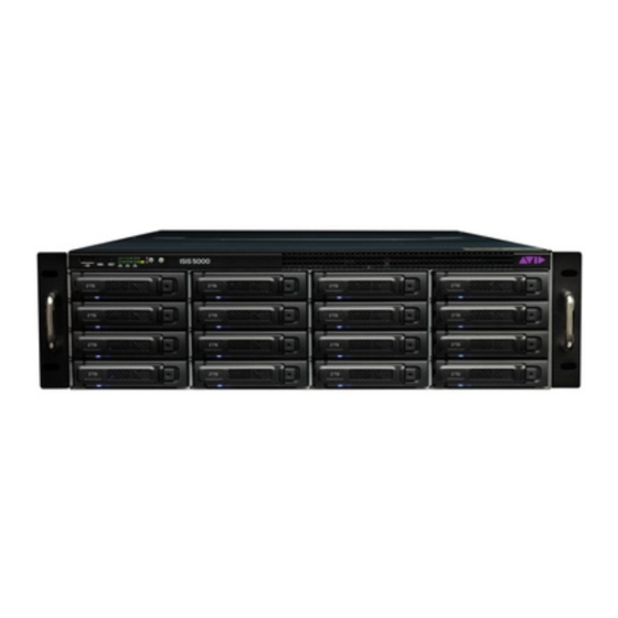
(Optional) Quad Port 1 Gb Ethernet adapter board Avid ISIS Front Panel The Avid ISIS 5500 comes with an Avid bezel that covers the front of the enclosure and can be locked to prevent unauthorized personnel from accessing the buttons and data drives. The... - Page 15 Front of the Enclosure With Bezel The front of the Avid ISIS provides access to 16 data drives, a USB port, network port activity LEDs, an error LED, and the Power and Reset buttons. The following is an illustration with the front bezel removed.
-
Page 16: Data Drive Led Functions
Avid ISIS Hardware Data Drive LED Functions 6 Gb SAS Expander — Data Drive LED Functions Management Console Drive State Blue LED Red LED Messaging Comments Online Inactive On solid No Special Status Healthy online drive, no disk I/O On-line Active... - Page 17 Avid ISIS Hardware System Director Front View Control panel The following table describes the control panel shown in the previous figure. System Control Panel Letter Description Description Universal serial bus (USB) port USB 2.0 device port on the front of the system supports one USB device.
-
Page 18: Drive Array And Slot Locations
Each Engine provides 16 TB in the ISIS 5500-16 and 32 TB in the ISIS 5500-32 and 64 TB in the ISIS 5500-64 of storage with the option to bind up to six Engines for a possible total of 384 TB. -
Page 19: Downloading And Installing The Lsi Megaraid Storage Manager Utility
2. Click Support >Find Help > Find Support Documents & Downloads by Product. 3. In the Search by keyword box enter 9260-4i (This is the model of the Raid Controller installed in the ISIS 5500 chassis.) 4. Expand Management Software and Tools. -
Page 20: Raid Behavior In The Engine
Once the three RAID groups have been created, any of the drives in the Engine can be swapped within the Engine. The Avid ISIS uses the drive IDs to track what five drives are members of each of the three RAID groups. -
Page 21: System Drives
Avid ISIS enclosure. As soon as a replacement system drive is installed, the working system drive creates a mirror of the original drive on the new drive. -
Page 22: Activating The License Key
Avid ISIS Networks Activating the License Key You need to activate your Avid ISIS software before you can make an Active File System. After installing your software, see “Avid ISIS Software Licensing” on page 98 Previous versions of Avid ISIS software use an application key plugged into the System Director to allow clients to connected to the ISIS infrastructure. - Page 23 8 to 11 from top to bottom. • The Quad Port 1 Gb Ethernet adapter board does not ship installed in the ISIS 5500-64, ISIS 5500-32 or the ISIS 5500-16 Engines. This optional board is only supported in single Engine direct connect configurations when you want 5 to 8, 1 Gb clients connected to the ISIS Engine.
-
Page 24: System Director And Switch 1 Gb Connections
A 10 Gb connection between your Engine and switch allows you setup the switch and clients a greater distance away from the Avid ISIS system. You can use the 10 Gb port in the Engine for a single or multiple Engine configuration. When using multiple Engines, you are required to use the 10 Gb connection in the System Director and Engines to the switch. -
Page 25: Installation Consideration
Active and Standby System Directors. • Several Avid ISIS Ethernet client connection options are listed as follows. See the Avid ISIS ReadMe for the latest list of qualified Ethernet switches Up to five clients (including the 10GB client) can connect directly into the Intel Pro network ports (1, 3, 4, and 6) on the rear of the System Director (see “Direct Connect... - Page 26 You cannot mix ISIS 5500-64 (4TB), ISIS 5500-32 (2 TB) drives or ISIS 5500-16 (1 TB) drives in the same ISIS 5500 Engine. • Once a disk has been added to the data set it must not be moved between Avid ISIS enclosures. Doing so corrupts the data on that disk.
-
Page 27: Optional Network Adapter Boards
This chapter provides procedures for adding and replacing network adapter boards in your Avid ISIS 5500. Do not add any hardware if there are any issues with the system. Correct all problems before adding new hardware and making changes to the system. Perform a quick check to verify that the system is in good working order. -
Page 28: Electrostatic Discharge Precautions
Electrostatic discharge (ESD) can damage disk drives, electronic components, and other parts. Avid recommends that you perform all procedures in this chapter only at an ESD workstation. If one is not available, provide some ESD protection by wearing an antistatic wrist strap attached to chassis ground (any unpainted metal surface) on your Engine when handling parts. - Page 29 Removing and Installing the System Cover Removing the Top System Cover Front Pull tabs Top cover screws Thumb screws To install the server system cover: 1. Place the cover over the Engine so that the side edges of the cover sit just outside the Engine sidewalls.
-
Page 30: Installing The Adapter Board
Removing and Installing the System Cover Installing the Adapter Board To install the adapter board: 1. Observe the safety precautions described in “Electrostatic Discharge Precautions” on page 2. Remove the Engine as previously described, see “Removing and Installing the System Cover”... -
Page 31: Myricom 10-Gb Driver And Configuration Settings
A copy of the Intel driver can be found in the Avid ISIS software kit: \Drivers\ISIS 5000\Intel_Pro1000\Intel_17.4_Win2K8-8-7-Vista_64 If you have made a change to the Intel settings and want to set them back to the Avid defaults, re-run the ISIS software installer (autorun.exe) and the Avid network settings are re-applied. If the network setting are not set to the Avid defaults, a message is displayed in the ISIS Management Console. -
Page 32: Installing The Avid Isis System
The Windows Product Key Certificate of Authenticity is attached to the top of the Engine. The standard Avid ISIS components: • Data drives — Each Engine has sixteen, 1 TB (ISIS 5500-16) or 2 TB (ISIS 5500-32) or 4TB (ISIS 5500-64) externally accessible, data drives. •... -
Page 33: Installing Avid Isis Hardware In A Rack
Once both the inner and outer rails are in place, slide the Engine with the inner rails attached into the outer rails. Secure the Avid ISIS Engine in the rack so it does not slide forward. - Page 34 Installing Avid ISIS Hardware in a Rack Avid ISIS airflow is from the front of the enclosure to the rear. Make allowances for cooling air to be available to the front panel surface and no restrictions at the rear. •...
-
Page 35: Positioning The Avid Isis Engine In The Rack
The following information helps you decide where to install the Avid ISIS in the rack. To position the Avid ISIS in the rack enclosure: Select a position in the rack where the Avid ISIS is at the proper baseline position. Positioning the Avid ISIS 5500... -
Page 36: Attaching Inner Slide Rails To The Avid Isis 5500
4. Repeat these steps to separate the second slide rail. Attaching Inner Slide Rails to the Avid ISIS 5500 Attach the inner slide rails that were separated from the outer slide rails to the Avid ISIS 5500. To attach the inner slide rails: 1. -
Page 37: Attaching The Outer Rails To A Square-Hole Rack
Installing Avid ISIS Hardware in a Rack Attaching the Inner Slide Rails 3. Repeat this procedure to attach the other inner slide rail on the other side of the Engine. Attaching the Outer Rails to a Square-Hole Rack After separating the slide rails as previously described (see “Separating the Slide Rails”... - Page 38 Installing Avid ISIS Hardware in a Rack Positioning the Outer Slide Rail with the Front Rack-Mounting Rail 3. Push the outer rail towards the outside of the rack, to secure the outer rail in place Insert the Outer Slide Rail to the Front Rack-Mounting Rail 4.
-
Page 39: Attaching The Outer Rails To A Round-Hole Rack
Installing Avid ISIS Hardware in a Rack Securing the Outer Slide Rail to the Rear Rack-Mounting Rail 6. Repeat this procedure to attach the second outer slide rail on the other side of the rack. Attaching the Outer Rails to a Round-Hole Rack After separating the slide rails as previously described (see “Separating the Slide Rails”... - Page 40 Installing Avid ISIS Hardware in a Rack 2. With the bracket assembly tabs aligning with the cut-out in the round hole adapter, swing the adapter so that the holes face the front of the bracket assemble as shown in the following illustration.
-
Page 41: Securing The Avid Isis 5500 In A Rack
Engine) are align with the outer slide rails secured to the rack. 2. Push the front of the Avid ISIS 5500 flush against the front mounting rail. The holes in the Avid ISIS Engine front panel align with the holes in the front mounting rail. -
Page 42: Installing The Force10 S25 And S4810 Switches In A Rack
Installing Avid ISIS Hardware in a Rack Front Panel Screws 1 of 4 Rack enclosure screws front mounting rail Installing the Force10 S25 and S4810 Switches in a Rack Make sure you have at least 1U of rack space available prior to installing. The illustrations in this section show the Force10 S25N switch, but the Force10 S25P and Force10 S4810 switches are rack-mounted in the same way. -
Page 43: Installing The Force10 S60 Switch In A Rack
Installing Avid ISIS Hardware in a Rack 2. Lift and position the switch so that the rack-mount brackets you attached are aligned with the front outer rack rails. 3. Position the front of the switch flush against the front mounting rails so that the holes in the switch bracket align with the holes in the front mounting rails. - Page 44 Installing Avid ISIS Hardware in a Rack To secure the Force10 switch to the rack enclosure: 1. Attach the rack-mount brackets using the four small flat-head screws on each side. Rack-mount brackets View from rear Screws Rack-mount brackets Power Supply Front 2.
-
Page 45: Installing The Avid Isis Drives
1/2 inch of the drive carrier should be outside the Engine. 6. Push the handle into the drive carrier. This seats the drive in the Avid ISIS. You’ll hear a click when the drive is fully seated and the handle latches in place. - Page 46 Connecting a Keyboard, Monitor, and Mouse There are only two USB ports on the rear of the Avid ISIS Engine. One of the ports is typically used for the application key. When you purchase your KVM switch make sure it includes a USB splitter cable so that both your keyboard and mouse can plug into the splitter cable and use a single USB port on the Engine.
-
Page 47: Connecting Power Cords
Your network switch might not have a Power switch and might be powered on when you plug the power cords into a power outlet. 3. Plug the KVM switch power cord into a power outlet. Configuring Considerations The Avid ISIS 5500 can be configured in the following ways:... -
Page 48: Connecting Clients Directly To The System Director
Connecting Clients Directly to the System Director You can connect up to eight clients directly into the Avid ISIS 5500. Each client needs to be configured on a separate subnet. The Intel Pro network port on the ISIS 5500 and the client network port need to be configured with different IP addresses on the same subnet. -
Page 49: System Director 1 Gb Ethernet Connections To The Switch
“Loading the Software” on page System Director 1 Gb Ethernet Connections to the Switch The following instructions describe how to connect the Avid ISIS 5500 to an Ethernet switch using the 1 Gb Ethernet ports. To install the Ethernet switch: 1. - Page 50 3. Attach one end of your Ethernet cable to each of the four outside 1 Gb Ethernet ports on the back of the Avid ISIS 5500. These ports are the Intel Pro network ports and labeled 1, 3, 4, and 6.
-
Page 51: Force10 Ethernet Switches
1 Gb Ethernet connections Avid ISIS 5000 5. Plug in the two switch power cords to power on the switch. The Avid switch configuration file is automatically loaded in the Force10 switches. If you need to change your switch configuration, see Avid Network and Switch Guide included in the Documentation folder of the software kit. -
Page 52: Force10 S25 Switch Modules
10 Gb Ethernet module or 12 Gb stacking modules. The 10 Gb module provides a 10 Gb Ethernet connection between the Avid ISIS 5500 Engine and the switch. The 12 Gb module is for stacking two Force10 switches, one module is needed in each switch. Modules are ordered separately and can install in either slot on the back of the Force10 switch. -
Page 53: 10 Gb Ethernet S25 Switch Connections
10 Gb Ethernet S25 Switch Connections The 10 Gb Ethernet board in the Avid ISIS connects to a switch using the 10 Gb Ethernet connection. If you need to connect more than 20 clients using the S25 switch, see “Stacking the... - Page 54 Inserting the XFP Transceiver into to the 10 Gigabit Ethernet Port 7. Insert an SFP+ transceiver into the 10 Gb Ethernet connector in the Avid ISIS Engine. Insert the SFP+ Transceiver into to the 10 Gigabit Ethernet Port on the Engine...
- Page 55 10. (Additional Engines) Attach one end of the 10 Gb Ethernet cable to one of the 10 Gb ports on the back of the switch and the other end to the 10 Gb port on the Avid ISIS Engine. If connecting a third or four Engine configuration, a second 10 Gb module needs to be installed in the Force10 Switch, see “Force10 S25 Switch Modules”...
-
Page 56: Stacking The Force10 S25 Switches
Force10 switches, see the documentation provided by the switch manufacturer. The stacked switch configuration uses SFP connectors to connect the cables to the switch. If using a stacked switch configuration, the 10 Gb connection from the Avid ISIS can be to either switch. -
Page 57: Connecting Multiple Engines To The Stacked Switch
Gb or stacking modules. 7. Plug-in the two power cord to power on your switch. The Avid switch configuration file automatically detects the 12 Gb modules. If you need to change your switch configuration, see Avid Network and Switch Guide included in the Documentation folder of the software kit. - Page 58 7. (Additional Engines) Attach one end of the 10 Gb Ethernet cable to one of the 10 Gb ports on the back of the switch and the other end to the 10 Gb port on the Avid ISIS Engine. Optional Engines can be connected to any 10 Gb port on the switch, although, the following...
-
Page 59: Force10 S60 Switch Modules
The Force10 switch has two expansion slots: one in the front and one in the back of the switch. The 10 Gb module provides a 10 Gb Ethernet connection between the Avid ISIS Engine and the switch. The 24 Gb module is for stacking two Force10 switches, one module is needed in each switch. -
Page 60: 10 Gb Ethernet S60 Switch Connections
SFP Ports 10 Gb Ethernet S60 Switch Connections The 10 Gb Ethernet board in the Avid ISIS connects to a switch using the 10 Gb Ethernet connection. If you need to connect more than 44 clients using the S60 switch, see “Stacking the... - Page 61 Inserting the SFP+ Transceiver into to the 10 Gigabit Ethernet Port 7. Insert an SFP+ transceiver into the 10 Gb Ethernet connector in the Avid ISIS Engine. Insert the SFP+ Transceiver into to the 10 Gigabit Ethernet Port on the Engine...
- Page 62 10. (Additional Engines) Attach one end of the 10 Gb Ethernet cable to one of the 10 Gb ports on the front of the S60 switch and the other end to the 10 Gb port on the Avid ISIS Engine.
-
Page 63: Stacking The Force10 S60 Switches
The stacked switch configuration uses SFP+ connectors to connect the cables to the switch. If using a stacked switch configuration, the 10 Gb connection from the Avid ISIS can be to either switch. Install a 24 Gb stacking module into the front left slot of the Force10 S60 switch, similar to the process described in “10 Gb Ethernet S60 Switch Connections”... -
Page 64: Force10 S4810 Port Configuration
The S4810 switch ports are numbered as shown in the following illustration. Engines and clients connect as follows: • Avid ISIS 5500 Engines connect via 10 Gb to ports 0 – 5 (these six ports are configured for 10 Gb connections and require 10 Gb transceivers) •... - Page 65 7. (Additional Engines) Attach one end of the 10 Gb Ethernet cable to one of the 10 Gb ports on the back of the switch and the other end to the 10 Gb port on the Avid ISIS Engine. Optional Engines can be connected to any 10 Gb port on the switch, although, the following...
- Page 66 Connecting Multiple Engines to the Stacked Switch Four Engines to a Stacked Switch Second Engine Third Engine Fourth Engine 10 Gb Ethernet LC to LC connection Engines are connected to ports 0 through 5. You must use an SFP+ transceiver for 10 Gb connections.
-
Page 67: Connecting To An In-House Network
Ethernet local area network (LAN). You need to modify the Avid default configuration in the Avid ISIS switch to add your corporate network to the Avid ISIS environment, see Avid Network and Switch Guide included in the Documentation folder of the software kit. -
Page 68: Turning On The Avid Isis 5500 Hardware
Ethernet ports 2 or 5 on the back of the Avid ISIS 5500 do not support the bandwidth needed for editing clients. Ports 2 and 5 are used for System Director Resiliency, see “Configuring System... -
Page 69: Installing The Avid Isis Software
Log on as Administrator and is-admin as the password. Setting the Date, Time, and Time Zone You need to correctly set the date, time, time zone, and daylight saving time option on each Avid ISIS enclosure. To set the date, time, time zone, and daylight saving time option on the Avid ISIS: 1. -
Page 70: Specifying A Unique Computer Name
Your Avid ISIS enclosure has been imaged at Avid with the current operating system configuration and drivers that have been qualified with the Avid ISIS system. This image creates a unique Host name for the system based on the MAC ID of the system board. If you change the Computer Name of the system you need to remember to rename the computer after re-imaging the system. -
Page 71: Virtual System Name
“Creating an Active File System” on page Once you have a virtual name it is stored in the registry and preserved when performing an Avid ISIS software upgrade. This means if you have created a unique virtual name for your System Director, you do not need to re-apply the virtual name after performing an upgrade or reinstalling the software. -
Page 72: Ip Addressing Strategies When Connecting To A Network
• You must assign a static IP address to the four Intel Pro 1 Gb ports or 10 Gb port on the Avid ISIS Engine. Avid has provided a Configure Network Adapter tool, see “Checking or... - Page 73 You can run the software installer from the USB flash drive. The advantage of copying the software kit to the Avid ISIS 5500 is that you have easy access to kit files if you should ever them in the future.
- Page 74 ReadMe file that provides the latest information regarding the ISIS system and software. You must have Adobe Reader installed to view the PDF. 7. Pick the Avid ISIS 5500 software for the enclosure you are installing the software on. The list of Actions change based on your selection.
- Page 75 File Gateway server. This software is included with the ISIS 2000 System Director software and cannot be installed on the same server as the ISIS 7000 or ISIS 5500 System Directors. If setting up the ISIS File Gateway, see the Avid ISIS File Gateway Setup and User’s Guide.
- Page 76 • Network Adapter IP Configuration — Displays a Configure Network window for configuring the IP address of the Avid ISIS network ports being used. It only appears when the network ports have not been configured (typically during the initial setup).
- Page 77 System Director. The Avid ISIS software can be installed without licensing the software but you cannot make an Active File System or connect any clients until you run the Avid License Control tool and activate the ISIS software. For instructions see “Avid ISIS Software Licensing”...
- Page 78 AvidISISDocumentation folder on the Avid ISIS installer kit. Browse Content This is a link that brings you directly to the Avid ISIS installer kit. From here you can access all the files included in the kit. This folder can be wherever the installer files have been saved.
- Page 79 You must use the Network Configuration Tool in the ISIS Launch Pad to set the Ethernet ports on the Avid ISIS 5500. This tool sets the IP addresses in the registry. Manually setting the IP addresses on the ISIS 5500 with out using the Network Configuration Tool is not supported.
- Page 80 Software Installation Default IP Network Addresses for 1 Gb and 10 Gb Direct Connect Clients ISIS 5500 Client Location IP Network Address IP Network Address Subnet Mask Direct connect — 10 Gb port 192.168.17.10 192.168.17.100 255.255.255.0 Direct connect — Pro1000 port 1 192.168.11.10 192.168.11.100...
- Page 81 Software Installation Configure the four ports using the Avid ISIS 5500 software Network Configuration Tool. Avid recommends the IP Network Address configuration shown in the following table: Default IP Network Addresses for 1 Gb Connections to a Single Switch Location...
- Page 82 Software Installation Configure each Engine using the Network Configuration Tool. Avid recommends the IP Network Address configuration shown in the following table: Default IP Network Addresses for a Single 10 Gb Connection to the Switch Location IP Network Address Subnet Mask System ID 1 192.168.255.17...
- Page 83 Software Installation Configure each Engine using the Network Configuration Tool. Avid recommends the IP Network Address configuration shown in the following table: Default IP Network Addresses for Multiple 10 Gb Connections to the Switch Location IP Network Address Subnet Mask System ID 1 192.168.255.21...
-
Page 84: Activating The License Key
With no client traffic on the system, this will take approximately 54 hours for the ISIS 5500-64, 27 hours for the ISIS 5500-32 and 14 hours for the ISIS 5500-16. During this initialization, the system is functional and able to support a limited amount of client traffic. An Avid ISIS Engine during initialization should be able to support full bandwidth to one client. -
Page 85: Creating An Active File System
Software Installation Do not lose the USB application key. Your Avid ISIS system does not function without it. If you lose the USB application key, you must purchase another one from Avid to use your Avid ISIS system software. To connect the application key to your Avid ISIS system: 1. - Page 86 4. (First System Director) Select Create Active File System and click OK. The Avid ISIS System Director service automatically starts when complete. In the System Director Control Panel, the “System Director is running” display turns green. 5. (Option) If creating a Standby System Director in an metadata redundancy configuration, “Configuring System Director Resiliency”...
-
Page 87: Checking Or Changing The System Director Ip Addresses
Configuration Tool window. To display the System Director IP Addresses: 1. (Option) If the ISIS Launch Pad is not displayed on the Avid ISIS 5500 System Director Desktop, click the ISIS Launch Pad icon in the Taskbar’s System Tray. The ISIS Launch Pad is displayed. -
Page 88: Accessing The Management Console From Any Computer
Install or upgrade the client software. To access the Management Console: 1. Type http://IP address of System Director in your browser. If your Avid ISIS network includes a Domain Name System (DNS), you can type the System Director’s name in the browser. -
Page 89: Binding The Storage Managers
After you have created an Active File System you need to bind the Storage Managers using the Management Console. If you have more than one Engine in your ISIS 5500 configuration, they appear listed in the Storage Manager page. One or multiple enclosures can be bound. -
Page 90: Creating A Storage Group
Create Workspaces after you have created your Storage Group. To create Workspaces, click Workspaces icon in the Management Console. See the Avid ISIS Administration Guide for information on creating Workspaces. -
Page 91: Creating User Accounts
Loading Client Software Avid ISIS client software is supported Windows, Macintosh and Linux clients. For information on using your client software see the Avid ISIS Client Guide. You can load the Client software in the following ways: If upgrading the Client Manager software using the file in the software kit or Installer page of the Management Console, you must first uninstall the Client Manager software using the Windows Control Panel before installing a new version of Client Manager. - Page 92 Loading Client Software 3. Type http://IP address of System Director in your browser. If you Avid ISIS network includes a Domain Name System (DNS), you can type the System Director’s name in the browser (default Virtual name is AvidISIS). The ISIS Management Console opens.
- Page 93 7. Restart the client when prompted. The client software starts automatically when restarted. 8. You might need to update the Intel Pro driver on your client system, see Avid ISIS ReadMe. 9. Repeat this procedure on each Avid ISIS Windows client.
- Page 94 Follow the on-screen instructions. The installer replaces earlier versions of the software (if any). 4. Repeat this procedure on each Avid ISIS Macintosh client. You can manually copy the client installers to a USB flash drive. The Macintosh client software installs an uninstaller application located at Applications .
-
Page 95: Configuring Client Software
(Linux) Click Applications > System Tools and select Avid ISIS Client Manager. To add the Client Manager launcher icon to the panel or desktop when using a Linux client, click Applications > System Tools and right-click Avid ISIS Client Manager and select add launcher to panel or desktop. - Page 96 Configuring Client Software 3. The first time you login, you might need to select a Remote Host (Avid ISIS system). For information adding a remote host, see the Avid ISIS Client Guide. 4. Select the ISIS system in the Systems panel.
-
Page 97: Configuring The Client Network Properties
Before you can connect your clients to the Avid ISIS network, you must configure the network properties on each client. If using the default Avid ISIS 5500 setup, you need to set a static IP address and subnet mask for the Ethernet port connection on every client. For instructions on setting the network properties on each client, see the Avid ISIS Client Guide. -
Page 98: Avid Isis Software Licensing
Avid ISIS Software Licensing When installing a new Avid ISIS system, you need to activate the ISIS software with the Avid License Control tool. If you have a dual System Director environment, you need to repeat the procedure for each System Director. -
Page 99: What You Need To Activate The Isis Software License
To activate the ISIS software license from the System Director with an Internet connection: 1. Locate your System ID and Activation ID card included with your new System Director. 2. Open the Avid License Control tool, click Start > Programs > Avid > Utilities > Avid License Control. - Page 100 License Activation Using an Internet Connection After your Avid software is activated, the License Profile tab displays your System ID, Activation ID, and Device ID. 3. Click Activate next to the Avid ISIS software. 4. Select “I am connected to the Internet and will use this computer” and then click Continue.
-
Page 101: License Activation Without An Internet Connection
Activate your software license on your second System Director. If you have purchased a “Resilient” System Director for the ISIS 5500, both System Directors use the same System ID in a dual System Director configuration. You do need a separate Activation ID for each System Director. - Page 102 To activate the ISIS software license from a separate computer: 1. Locate your System ID and Activation ID card included with your new System Director. 2. Open the Avid License Control tool, click Start > Programs > Avid > Utilities > Avid License Control.
- Page 103 A USB flash drive is a good method of moving the license.bin file to the System Director. 12. Close the Web browser on the computer with the Internet connection. 13. Return to the ISIS System Director where you left off in the Avid License Control tool (see the illustration in step 8) and click Next.
-
Page 104: Deactivating The License
Internet connection to deactivate the software and its options. Deactivating the ISIS System Director software: 1. Stop your Avid ISIS System Director. 2. Open the Avid License Control tool, click Start > Programs > Avid > Utilities > Avid License Control. The Avid License Control tool opens. -
Page 105: Configuring System Director Resiliency
• If all Engines in your ISIS 5500 environment are configured as a single Storage Group, and the Active System Director failure takes down both the System Director and the Storage Manager services (as in a power loss or operating system failure), the Standby System Director takes over as Active. - Page 106 System Director. Then create a new Standby Filesystem on the new System Director. If you re-image your System Director or ISIS 5500 Engine to an operating system not previously shipped with that enclosure, the Windows license is not valid for the new operating system.
-
Page 107: Connecting Dual System Directors
System Director. This information is not currently replicated to the Standby System Director and must be entered manually on both System Directors. For information on setting up the notification service, see Setting up Error Notification in the Avid ISIS Administration Guide. -
Page 108: Configuring A Second System Director
“Stopping and Restarting the System Directors” on page 116 Setting IP Addresses for Crossover Link Avid provides default System Director IP addresses for System Director Resiliency. If you use different addresses, be sure to note them and have them available before proceeding. The Network Configuration Tool provides a section for setting the IP address when configuring Dual System Directors. - Page 109 You must use the Network Configuration Tool in the ISIS Launch Pad to set the Ethernet ports on the Avid ISIS 5500. This tool sets the IP addresses in the registry. Manually setting the IP addresses on the ISIS 5500 without using the Network Configuration Tool is not supported.
-
Page 110: Configure The Resiliency Connection
Software” on page 2. Stop the Active System Director, click System Director Control Panel from the ISIS Launch Pad or Start > Programs > Avid > ISIS System Director and select Control Panel. 3. Click Stop System Director. 4. Click the Change button beside the Virtual System Director Name and type a name in the Virtual System Director Name text box and click OK. - Page 111 If you create a new file system on a System Director that already has a file system all of your existing data will be lost. The Avid ISIS System Director service automatically starts when complete. In the System Director Control Panel, the “System Director is running” display turns green.
- Page 112 Configuring a Second System Director Enable Dual System Director Configuration 9. Select “Enable Dual System Director Configuration.” 10. Configure the Virtual Addresses on both systems by doing the following: a. Choose an unused static IP address that are used as the Virtual IP addresses for both System Directors.
- Page 113 To set up the resiliency connection on the Standby System Director: 1. Stop the Standby System Director, click System Director Control Panel from the ISIS Launch Pad or Start > Programs > Avid > ISIS System Director and select Control Panel. 2. Click Stop System Director.
- Page 114 Configuring a Second System Director Enable Dual System Director Configuration 5. Select “Enable Dual System Director Configuration.” 6. Configure the Virtual Addresses on both systems by doing the following: a. Choose an unused static IP address that are used as the Virtual IP addresses for both System Directors.
- Page 115 Configuring a Second System Director Green The numbers in the Packets Received boxes indicate the number of packets received from the first System Director On the Receiving System Director you see the packets received number incrementing for each connection. Packets received 14.
-
Page 116: Stopping And Restarting The System Directors
ISIS Control Panels on each system. Stopping and Restarting the System Directors In a ISIS 5500 Resiliency configuration, you can stop the Active System Director and watch the Standby System Director become the Active System Director. When you restart the System Director that was previously Active, that System Director now becomes the Standby System Director. - Page 117 To stop and start the System Director using the Launch Pad: 1. If the ISIS Launch Pad is not displayed on the Avid ISIS System Director Desktop, click the ISIS Launch Pad icon in the Taskbar’s System Tray to display or hide the Launch Pad.
-
Page 118: Binding Order For Health Monitoring
Binding Order for Health Monitoring To stop and start the System Director using the ISIS Control Panel: 1. Click Control Panel icon in the Launch Pad or Start > Programs > Avid > ISIS System Director and select Control Panel. - Page 119 Binding Order for Health Monitoring To set the network connection bindings order: 1. On the System Director, click Start > Settings > and double-click Network Connections. 2. Click the Advanced menu in the Network Connections window and select Advanced Settings. 3.
-
Page 120: Avid Isis Upgrade Guidelines
• Do not perform an Avid ISIS system upgrade if your network is not in optimum working order, see “Health Check” on page 120. -
Page 121: Software Upgrade
(www.avid.com/support/downloadcenter) or use the USB flash drive and copy the installer kit to your Engine. New Avid ISIS systems ship with the Avid ISIS software kit on the USB included with the system. Do not download and run the AvidISISStorageManager64.msi file shown in the Management Console Installer window to upgrade your Engines, because important configuration files are not included in the .msi file. - Page 122 Software Upgrade ® This includes AirSpeeds , AirSpeed Multi Streams, editing clients, and ancillary servers; for ® example Interplay servers. You do not need to shutdown the client if they can continue to work offline. AirSpeeds can continue to capture to their internal drives and editing systems can edit as long as they are not using workspaces.
-
Page 123: Isis Client Software Installation
Preferences are saved and you do not need to restart the client. The Macintosh client software installs an Avid_Uninstall folder. Use this folder only when you want all of the Avid client files removed; including the preference files. • For Linux clients — You must install and uninstall the Linux client software as described in the following procedures. - Page 124 Software Upgrade 6. Update the Intel Pro driver on your client system, see Avid ISIS Client Guide included in the Documentation folder of the software kit. 7. Repeat this procedure on each Avid ISIS Windows client. You can manually copy the client installers to a USB flash drive. The installers are in the Avid ISIS software kit located on [drive]: .
-
Page 125: Updating The 10 Gb Myricom Board Driver On Engines
If you have made a change to the Myricom settings and want to set them back to the Avid defaults, re-run the ISIS software installer (autorun.exe) and the Avid network settings are re-applied. - Page 126 Software Upgrade To install the Myricom driver on the Engines: 1. Copy the Myricom driver from the Avid ISIS 5000 software kit to the Avid ISIS 5000 Engine. The Myricom driver can be found on the Avid ISIS 5000 software kit in the...
-
Page 127: Post Upgrade System Verification
Post Upgrade System Verification Click Have Disk and browse to and select the \Drivers\ISIS 5000\Myricom\ Myricom v1.1.9 driver ( myri10ge.inf Click Open. k. Click OK. Click Next. m. Click Install in the Windows Security dialog box. 3. Close all windows restart the Engine. 4. - Page 128 To set PathDiag Tool: a. Do one of the following. (Windows) Select Start > All Programs > Avid > ISIS Client > PathDiag. (Macintosh) Select Go > Applications > AvidISIS folder. In this folder, double-click the PathDiag.app file.
-
Page 129: Preupgrade Information
Network Degraded states. Preupgrade Information Gather the following information before the upgrade. This information is critical to troubleshooting an Avid ISIS. • Current Avid ISIS software version • Avid ISIS Administrator password • Number of Avid ISIS engines •... -
Page 130: Switch Information
Preupgrade Information • Number of AirSpeeds • Other workgroup server details (for example Interplay; host names, passwords, and versions) Switch Information Note the following switch information: • Type of switch • Number of switches • Location of configuration files • (Optional) Network uplink information •... -
Page 131: Optional Storage Information
Preupgrade Information 10 Gb port IP Address Subnet Mask IP Address Dual System Director crossover port 1 Gb port 2 IP address Dual System Director crossover port 1 Gb port 5 IP address Default Gateway Optional Storage Information Fill out the following Engine and switch information for the on site equipment. Note the Engine 10 Gb links and the switch connections: Optional 2nd Engine, Serial Number IP address:... -
Page 132: On Site Spares
Spare data drive: On Site Spares Use the following list to assure that you have the correct parts onsite when performing any Avid ISIS upgrade. This can be a mix of customer spares and parts brought onsite by upgrade technicians. - Page 133 Preupgrade Information Spare Components and Cables (Continued) Part Quantity Firmware Version (if known) Ethernet switch Additional Parts Available...
-
Page 134: Adding And Replacing Hardware
The status remains yellow until the rebuild is finished and a new hot spare has been inserted. When the new hot spare is inserted, the ISIS 5500 automatically makes the raw drive into a spare. -
Page 135: Replacing A Drive
Removing and Replacing Data Drives To remove a drive from the Avid ISIS 5500: 1. Locate the data drive on the front of the ISIS 5500 that has the solid blue and red LEDs on solid. You do not need to wait for RAID groups to repaired before removing a failed drive. The RAID group uses the other four drives in the RAID to make the spare drive part of the group. -
Page 136: Swapping Data Drives To Different Capacities
In the left pane, click plus sign (+) beside Configuration and select Services. c. Right-click on the Avid ISIS Storage Manager and select Stop. 3. Swap all 16 data drives using raw drives or drives that were previously part of an array. -
Page 137: Replacing The Isis Engine
IP address, and other important network details, see “Preupgrade Information” on page 129. To replace an ISIS 5500 enclosure: 1. Power-off the old Engine by clicking Start > Shut Down. 2. Disconnect the two power cords from the back of the old Engine. - Page 138 Replacing the ISIS Engine 6. Remove the old Engine from the rack. 7. Install the new Engine into the rack (without the system or data drives). 8. Carefully reinsert the both system drives into the rear of the new Engine. If you recorded the locations from which the drives were removed on the original Engine, insert them into the same upper and lower locations.
- Page 139 Replacing the ISIS Engine e. Select the “Import logical configuration from all foreign drives” option and click OK. The Foreign Configuration Wizard window appears listing the foreign configurations. Click Accept.
-
Page 140: Adding Optional Storage
When you initially install the Avid ISIS software, the RAID set is initialized automatically. With no client traffic on the system, this will take approximately 54 hours for ISIS 5500-64, 27 hours for the ISIS 5500-32 and 14 hours for the ISIS 5500-16. During this initialization, the system is functional and able to support a limited amount of client traffic. - Page 141 ISIS Launch Pad icon in the Taskbar’s System Tray. The ISIS Launch Pad is displayed. You can also start the Network Configuration Tool by clicking Start > Programs > Avid > ISIS Storage Manager > Network Configuration Tool. 10. Click Network Configuration Tool, in the Storage Manager section of the Launch Pad.
-
Page 142: Replacing System Drives In The Engine
Engine. If you have a failure on either one of the two system drives you can pull the failed drive out of the Engine and install a replacement without turning off the Avid ISIS Engines. The Avid ISIS continues to run properly if one of the two system drives are removed. -
Page 143: Replacing System Drives In The Engine
Replacing System Drives in the Engine 3. Verify that you have the current copy of the Metadata by comparing the date in the Metadata tab of the ISIS control Panel. 4. Start the System Director service using the ISIS Control Panel. Replacing System Drives in the Engine If replacing the system drives as part of a complete Engine replacement, see “Replacing the ISIS... - Page 144 Replacing System Drives in the Engine 3. Pull the failed drive out of the Engine and install a replacement without turning off the Engine. Once the drive is installed, use the Intel Rapid Storage Technology application to initiate the rebuild operation as described in the following steps. 4.
-
Page 145: Moving The Metadata To A New System Director
Moving the Metadata to a New System Director Use the following procedure if you need to move the Metadata from one Avid ISIS System Director to another Avid ISIS Engine and make that the System Director. To move the System Director Metadata: 1. -
Page 146: Switch Replacement
7. Copy the Partition0 and Partition1 files (and PartitionDump.bin file if copied) into the following location on the System Director: D:\Program Files\Avid\ISIS System Director\ 8. Start the new System Director service using the ISIS Control Panel. 9. Verify that the System Director is now running. Start the Management Console and verify that all workspaces are listed. - Page 147 Switch Replacement 5. Reload the switch configuration and old switch configuration should be restored on the new switch. The specific commands will be different between Cisco and Force10 but they all should be in the switch configuration guide. If a TFTP server is not available: Use a console/telnet client such as PUTTY to list the configuration and copy it to a text file, which can then be pasted back into the new switch and save to NVRAM.
-
Page 148: Permanently Removing An Isis Engine
7. Reconnect all network cables in the front of the switch. Permanently Removing an ISIS Engine Use the following procedure if you have multiple ISIS 5500 Engines in your ISIS 5500 environment and want to remove an Engine. Such a scenario might include setting up a second ISIS 5500 environment. - Page 149 Permanently Removing an ISIS Engine 2. Once you have resized the Workspaces, open the Storage Group page and select the Storage Element (Engine) you want to remove and click Remove. Use the Engine Host Name or serial number to identify what Storage Element to be removed and then use the serial number to identify that Engine in the rack.
-
Page 150: Chapter 9 Product Recovery
You might need to reinstall the Windows Storage Server 2008 R2 operating system on your Avid ISIS Engine if you are directed to do so by Avid Customer Support or if you are initializing a new drive. The reinstallation offers you two options: •... -
Page 151: Creating A Product Recovery Usb Flash Drive
To create a product recovery USB flash drive: 1. Locate the 16 GB USB flash drive Avid provided with the Avid ISIS and insert it into the front USB port. 2. Click “Create Recovery USB Drive” from the installer splash screen or double-click the AvidRecoveryImageTool.exe file included in the software installer kit from the following... - Page 152 Creating a Product Recovery USB Flash Drive 3. Click Select Image to locate the product recovery image from the C:\Image folder of the Avid ISIS system drive (you need to browse to the location of the .ari file). 4. Select the .ari file.
-
Page 153: Reinstalling The Windows Storage Server 2008 R2 Operating System
Remove the USB flash drive from the Avid ISIS. Reinstalling the Windows Storage Server 2008 R2 Operating System To reinstall the Windows Storage Server 2008 R2 operating system from the Avid Product Recovery flash drive: 1. Make sure all clients stop any activity and unmount their workspaces. - Page 154 Reinstalling the Windows Storage Server 2008 R2 Operating System 11. Select the Advanced tab > IPMI Configuration, make sure “Restore on Power Loss” is set to [Last State]. 12. Press F10 to Exit and Save your changes. The system continues to start from the USB flash drive. Wait until two windows appear, click on the blue window and select one of the available options: Recover the C: partition only.
-
Page 155: Configuring The System Drive Using Windows 2008 Storage Server Setup
The Product Key Authenticity is verified with Microsoft through an Internet connection. If you do not have the Avid ISIS connected to an in-house network, you need to phone in your Product Key and get an Authenticity number back from Microsoft. - Page 156 Configuring the System Drive Using Windows 2008 Storage Server Setup 7. Start the system and install Avid ISIS software, see “Installing the Avid ISIS Software” on page...
-
Page 157: Specifications And Notices
This section provides information on the dimensions and weight, the environmental, the electrical, and the power cord specifications for the Avid ISIS 5500 and qualified Ethernet switch. It also recommends the use of an Uninterruptible Power Supply and supported network cabling. -
Page 158: Uninterruptible Power Supply (Ups)
Windows servers to send alerts to other Windows servers to perform actions. Your Avid ISIS 5500 is connected to a network, network policy settings might also prevent you from completing this procedure. Make sure there is adequate power and the correct receptacle type for each hardware component, the rack power strips, and the UPSes. - Page 159 350 MHz for maximum length. System Directors and clients to 1 Gb ports on an ISS The minimum GigE cable length for Avid network products is 6 feet or 2 meter. Avid Interplay servers to shared storage networks...
- Page 160 100 Mb Ethernet, up to 2000 meters (FX) 1 Gb Ethernet, 1000 meters (SX) 10 Gb Ethernet, 550 meters (SR) Avid supports single-mode fiber cable using 1310 nm transceivers (long distances): • SMF ITU G.652.A/B 9 micron cable up to...
- Page 161 Supported Cabling Supported Cables (Continued) Cable Connection Connector Style and Maximum Cable Type Function Length Avid ISIS Transceiver used in: LC connector SFP+ optical transceivers Force10 S25P and S60 optical • SFP+ multi-mode short range (SR) 850nm switches JDSU – PLRXPL-SC-S43-21-N JDSU –...
-
Page 162: Appendix A Safety And Regulatory Information
Operate the device within its marked electrical ratings and product usage instructions. If you need to replace a battery in an Avid hardware unit, be sure to use the correct battery type. There might be a risk of explosion if a battery is replaced by an incorrect type. -
Page 163: (Hebrew Warnings And Cautions)
(Hebrew Warnings and Cautions) For products with a power switch the main power switch should remain accessible after installation. (Hebrew Warnings and Cautions) FCC Notice Part 15 of the Federal Communication Commission Rules and Regulations has established Radio Frequency (RF) emission limits to provide an interference free radio frequency spectrum. Many electronic devices produce RF energy incidental to their intended purpose. -
Page 164: Modifications
Canadian Notice (Avis Canadien) Modifications The FCC requires the user to be notified that any changes or modifications made to Avid hardware that are not expressly approved by Avid Technology may void the user’s authority to operate the equipment. Cables Connections to Avid hardware must be made with shielded cables with metallic RFI/EMI connector hoods in order to maintain compliance with FCC Rules and Regulations. -
Page 165: (Hebrew Led Safety Notices)
Declaración de Confomidad Verklaring de overeenstemming Dichiarazione di conformità We/Wir/Nous/WIJ/Noi: Avid Technology 75 Network Drive Burlington, MA, 01803 USA European Contact: Nearest Avid Sales and Service Office or Avid Technology International B.V. Sandyford Industrial Estate Unit 38, Carmanhall Road Dublin 18, Ireland... - Page 166 Product Name(s): ISIS 5500 Model Number(s): 7020-30085-XX Product Option(s): This declaration covers all options for the above product(s).
-
Page 167: Disposal Of Waste Equipment By Users In The European Union
Argentina Conformity Made in USA Australia and New Zealand EMC Regulations Ken Hopkins Avid Technology (Aust) Pty Ltd c/o – Elliot House Suite 810, Level 8 140 Arther St North Sydney NSW – 2060... -
Page 168: Japan Emc Regulations
Japan EMC Regulations Japan EMC Regulations Class A Equipment This is a Class A product. In a domestic environment this product may cause radio interference in which case the user may be required to take corrective actions. VCCI-A Korean EMC Regulations Class A Equipment Please note that this equipment has obtained EMC registration for commercial use. - Page 169 Taiwan EMC Regulations Warning Statement 1. UV ray radiation Following statement or equivalent: Following marking or other equivalent marking: 2. Operator touchable area protection Operation manual should have following statement and statement should be shown on device, or put on similar sentence: 3.
- Page 170 Taiwan EMC Regulations 4. Mechanical hazards Injury may result from: Sharp edges and corners Moving parts which have the potential to cause injury Equipment instability Flying particles from imploding cathode ray tubes and exploding high pressure lamps Examples of measures to reduce risks include: Rounding of sharp edges and corners Guarding Provision of SAFETY INTERLOCKS...
- Page 171 Taiwan EMC Regulations Examples of measures to reduce risks include: Avoiding the use of constructional and consumable materials likely to cause injury by contact or inhalation during intended and normal conditions of use Avoiding conditions likely to cause leakage or vaporization Provision of markings to warn USERS about the hazards 7.
- Page 172 Taiwan EMC Regulations 10. Replaceable batteries If an equipment is provided with a replaceable battery, and if replacement by an incorrect type could result in an explosion (for example, with some lithium batteries), the following applies: If the battery is placed in an OPERATOR ACCESS AREA, there shall be a marking close to the battery or a statement in both the operating and the servicing instructions If the battery is placed elsewhere in the equipment, there shall be a marking close to the battery or a statement in the servicing instructions...
- Page 173 Taiwan EMC Regulations 11. Warning to service persons Suitable markings shall be provided on the equipment or a statement shall be provided in the servicing instructions to alert a SERVICE PERSON to a possible hazard, where both of the following conditions exist: Where a fuse is used in the neutral of single-phase equipment either permanently connected or provided with a non-reversible plug Where, after operation of the fuse, parts of the equipment that remain energized might...
-
Page 174: Index
10 Gb Ethernet online support connection training services single switch 82, 83, web site switch addresses 81, Avid License Control tool 10 Gb module 52, 12 Gb stacking module 90 client configuration Bind Storage Managers Bind the Storage Managers Binding order... - Page 175 Index Canadian Connectors 1 Gb 20, 22, interference causing equipment regulations 164, Connectors 10 Gb 22, 168, Control panel Category 5 or 6 cables System Director 17, 85, 110, Checklist Create health of system 27, 120, New Active file system 86, 111, preupgrade Workspaces 88, Cisco...
- Page 176 Index See Drive Health check 27, 120, EIA rack units Health Monitor Enclosure storage Host name Engine Host name change, System Director removal Hot spare replacement House network Environmental requirements Ethernet 1 Gb connectors 20, 22, 10 Gb port 53, Indirect license activation cable In-house workgroup...
- Page 177 Index Keyboard connector Mirrored system drives KVM switch Modal bandwidth Modules 10 Gb switch stacking Monitor Launch pad icon 87, 117, connector LC cables 53, VGA connector Mouse connector described Multi-mode fiber cable drive activity Myricom board drive power Myricom configuration function Myricom Network Connection system drive...
- Page 178 Index Red LED System error Packets received Regulatory information Password Reinstall Windows administrator 68, 69, Removing an Engine Management Console 89, Replace PathDiag Tool drive PCI-X slots drive set with different capacity Ports engine gigabit Ethernet switch gigabit Ethernet to switch Requirements for rack mounting Intel Pro Resiliency...
- Page 179 Index modules switch configuration Taiwan EMC regulations Standby System Director Task bar icon 87, 117, Static IP addresses Time zone 69, Stop System Director 85, 110, 113, Training services Stop/Start server Transceiver Storage Group Storage Manager Agent SFP+ default password Storage Manager Installers Transceivers 54, Storage Manager Software...
- Page 180 Index 2008 operating system client network properties reinstall Windows clients Windows Update Workgroup, in-house Workspaces create number of XFP transceivers 54, 61,...
- Page 181 Avid Technical Support (USA) Product Information 75 Network Drive Visit the Online Support Center at For company and product information, Burlington, MA 01803-2756 USA www.avid.com/support visit us on the web at www.avid.com...
Need help?
Do you have a question about the ISIS 5500 and is the answer not in the manual?
Questions and answers