Table of Contents
Advertisement
OPERATING & MAINTENANCE MANUAL
WASCOMAT JUNIOR W 75
WASCOMAT SUPER JUNIOR W 105
WASCOMAT SENIOR W 125
WASCOMAT GIANT W 185
WARNING: ALL OPERATING AND MAINTENANCE PROCEDURES SHOWN ON THE NEXT
PAGE OF THIS MANUAL MUST BE FOLLOWED DAILY FOR PROPER OPERATION OF
YOUR WASCOMAT MACHINE.
PLEASE ENTER THE FOLLOWING INFORMATION AS IT APPEARS ON THE MACHINE(S)
DATA PLATE(S).
MACHINE TYPE OR MODEL
MACHINE SERIAL NUMBER(S)
ELECTRICAL CHARACTERISTICS: ________ VOLTS, _______ PHASE, _______ HZ.
MAKE CERTAIN TO KEEP THIS MANUAL IN A SECURE PLACE FOR FUTURE
REFERENCE.
471 1562-74/01
97.43
Advertisement
Table of Contents

Related Manuals for Wascomat Junior W 75


Summary of Contents for Wascomat Junior W 75
- Page 1 OPERATING & MAINTENANCE MANUAL WASCOMAT JUNIOR W 75 WASCOMAT SUPER JUNIOR W 105 WASCOMAT SENIOR W 125 WASCOMAT GIANT W 185 471 1562-74/01 97.43 WARNING: ALL OPERATING AND MAINTENANCE PROCEDURES SHOWN ON THE NEXT PAGE OF THIS MANUAL MUST BE FOLLOWED DAILY FOR PROPER OPERATION OF YOUR WASCOMAT MACHINE.
- Page 2 Be sure to keep the machine(s) in proper working order: Follow all maintenance and safety procedures. Further information regarding machine safety, service and parts can be obtained from your dealer or from Wascomat through its Teletech Service Telephone - 516/ 371-0700.
- Page 3 Be certain to relock after remounting the top panel. MANUFACTURED BY WASCATOR DISTRIBUTED BY WASCOMAT INWOOD, NEW YORK, USA 471 76 62 02 LOCATED ON THE DOOR:...
-
Page 4: Safety Instructions
Wascomat Junior W 75 • Wascomat Super Junior W 105 Wascomat Senior W 125 • Wascomat Giant W 185 Contents Introduction ..............1 Technical data ..............2 Installation ................ 7 Safety rules ..............15 Mechanical and electrical design ........16 Procedure ............... -
Page 5: Introduction
This manual contains a technical description of the Wascomat W75, W105, W125 and W185 model machines and instructions for their installation, operation and maintenance. Together with the wiring diagram which accompanies each individual machine it should be kept in a safe place for easy reference. -
Page 6: Technical Data
Technical data Technical data Wascomat Junior W75 Dry load capacity up to 7.5 kg 18 lbs Overall dimensions Width 660 mm 26 in Depth 649 mm 25 9/16 in Height 1050 mm 41 11/32 in Net weight 107 kg 235 lbs Dyn force 1.2±2.6 kN... - Page 7 Technical data Technical data Wascomat Super Junior W105 Dry load capacity up to 10 kg 25 lbs Overall dimensions Width 660 mm 26 in Depth 766 mm 30 5/32 in Height 1050 mm 41 11/32 in Net weight 147 kg 323 lbs 1.7 ±3.4 kN...
- Page 8 Technical data Technical data Wascomat Senior W125 Dry load capacity up to 16 kg 35 lbs Overall dimensions Width 745 mm 29 11/32 in Depth 995 mm 39 in Height 1196 mm 47 3/32 in Net weight 210 kg 462 lbs Dyn force 2.4±4.8 kN...
- Page 9 Technical data Technical data Wascomat Giant W 185 Dry load capacity up to 23 kg 51 lbs Overall dimensions Width 827 mm 32 5/8 in Depth 1085 mm 42 3/4 in Height 1315 mm 51 3/4 in Net weight 264 kg...
- Page 10 Technical data Outline and dimensions Electrical cable connection K J H 2447 W75, 105, 125 W185 1 Cold water 1 Cold water 2 Hot water 2 Hot water 3 Hot water W105 W125 W185 inches inches inches inches A 1050 41 11/32 1050 41 11/32...
-
Page 11: Installation
Installation Installation Machine foundation The machines are designed to be bolted in position to a concrete floor or specially prepared concrete foundation. A template showing the size of the foundation and positioning of the foundation bolts is delivered with each machine. For installation on an existing concrete floor, the floor must be at least 8"... - Page 12 Installation Mechanical installation Fig. • Place wide steel shims on the concrete foun- dation over the bolts. • Lift the machine and lower it in position. Never use the door or the door handle to lift or lower the machine. •...
- Page 13 Installation Electrical installation Although the machines are fitted with a thermal overload in the motor windings a separate three- Fig. phase common-trip circuit breaker must be installed for all three-phase machines. For proper overcurrent protection, check the data plate at the rear of the machine. Also consult local electrical code for special requirements.
- Page 14 Installation Water connection NOTE All plumbing must conform to national and local plumbing codes. Incoming water lines do not require non-return or back-suction valves, as the machine is already Fig. fitted with a siphon breaker. However, all inco- ming lines must be fitted with shut-off valves. •...
- Page 15 This will assure fill times of approximately 1 minute and normal cycle times. Wascomat washers are designed to operate at 25–85 PSI Call your local water utility company if you do not know the water pressure in your water main.
- Page 16 Do not reduce the size of the drain connection from the machine to the waste line. Start-up and safety checklist Before initial start-up of a Wascomat washer- extractor, the following safety checks must be performed: • Make sure the machine is properly bolted to Fig.
- Page 17 IMPORTANT: 1195 Door safety interlock must be checked daily in accordance with above procedure. WARNING: Before servicing Wascomat equipment, disconnect electrical power. 1196...
- Page 18 The warranty card should be completed and sent to Wascomat. All other items should be placed in a safe place for future reference. The machine should be cleaned when the instal-...
-
Page 19: Safety Rules
Safety rules Safety rules • This machine is designed for water washing only. • All installation operations are to be carried out by qualified personnel. Licensed personnel are necessary for all electric power wiring. • The interlock of the door must be checked daily for proper operation and must not be bypassed. -
Page 20: Mechanical And Electrical Design
Mechanical and electrical design General The door, cycle indicator, coin meter or manual start switches, control light and program-selection knob are located at the front of the machine. All control and indicating components, i.e. relays, level control, cycle timer, etc are assembled under the top cover, easily accessible from the top of the machine for simplified servicing. - Page 21 Mechanical and electrical design Machine construction Outer shell The outer shell is made of heavy gauge surgical steel and is attached to a heavy Fig. duty, rigid head casting (back gable). The whole assembly is mounted on a heavy gauge fabricated steel base, galvanized for long life and corrosion resistance.
- Page 22 Mechanical and electrical design Back gable and bearing The back gable and the bearing trunnion housing are constructed of a Fig. webbed heavy casting for extra rigidity. There are three neoprene seals to protect from filtration of water. The sleeve bearings are water protected. An intermediate safety outlet provides an escapement for any possible con- densation.
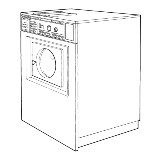
- Page 23 Mechanical and electrical design Door, description NOTE The door consists of a backing frame (1), door Fig. (2), glass (3) and door gasket (4). The backing Do not repair a faulty door lock. frame and door are both made of enameled Allways replace the old unit aluminium.
-
Page 24: Control Unit
Mechanical and electrical design Control unit Fig. The cycle timer(1) and rotary program selector(2) are mounted just behind the control panel. The relays (3) and level controls (4) are located at the top of the machine, easily accessible for service, as are the motor capacitors (5) on 1-phase models.. - Page 25 Mechanical and electrical design Relays The Wascomat W models employ two relays. Fig. The relays control: • the wash speed (1) • the extract speed (2) Construction The body of the relay holding the stationary Fig. contacts is made of current-resistant plastic. A solenoid and a contact bank hold the moving contacts.
-
Page 26: Drive Motor
Mechanical and electrical design Drive motor Description in general Fig. The motor is mounted on an axle with rubber dampeners. The V-belt is tightened by turning the motor on Fig. the axle and locking it in place using the tensioner on the rear side of the motor. The motor and tensioner have vibration and noise dampening rubber suspensions. - Page 27 Mechanical and electrical design Principal wiring and points of measuring on single-phase motors. The numbers at the connection points refer to the terminal num- Fig. bers at the motor connector plug. The numbers in circles indicate points of ampere measurements. 1216...
- Page 28 Mechanical and electrical design W125 208-240 V 60 Hz single-phase 1700...
- Page 29 Mechanical and electrical design 1791...
- Page 30 Mechanical and electrical design Motor connections Fig. 1, 2 and 3: wash speed (18-pole winding). 4, 5 and 6: extract speed (2-pole winding) 7 and 9: motor overload protector. Motor overload protector The motor is equipped with two self-resetting, Blue White thermal overload protectors, situated one in each Black...
- Page 31 Mechanical and electrical design Water level controls One pressure switch is used to control the correct water levels Fig. during various cycles of the washing program. Adjustment All pressure switches are factory-calibrated to meet specific requirements. The trip level for any one pressure switch can be changed only within narrow limits because each trip range requi- res a different set of springs.
- Page 32 Mechanical and electrical design Inlet valves Construction The valve has a single-inlet with either one, two Fig. or three outlets, each with its own solenoid coil. The body is made of heat-resistant polyamid plastic and the solenoids encased in water-tight plastic.
-
Page 33: Trouble Shooting
Mechanical and electrical design Maintenance instructions Limescale can block the hole in the valve diaph- ragm and interfere with the function of the valve. It is therefore advisable to dismantle and clean Fig. the valve at certain regular intervals. The fre- quency depends on operating conditions and the level of contamination in the water. - Page 34 Mechanical and electrical design Inlet valve for W75-W185 The water inlets have brass bodies with larger Fig. cross section of the outlet in order to achieve a shorter filling time for the machine. Construction Fig. The valve housing is made of pressed brass. The spring-loaded plunger is made of stainless steel and located at its lower end.
- Page 35 Mechanical and electrical design Soap supply box Fig. The three-compartment soap supply box is located at the top of the machi- ne. Viewed from the front, the compartments marked with figures 1, 2 and 3 are used as follows: Compartment 1 This compartment is used for adding detergent to the wash at the start of the Soak cycle.
-
Page 36: Drain Valve
Mechanical and electrical design Drain valve Description Fig. The drain valve is operated by using the pressure in the cold water intake. A tube (1) is connected between the cold water intake and a solenoid valve (2). When the solenoid valve is activated, it opens and allows water to flow into the feeder tube (3). -
Page 37: Procedure
Procedure Procedure for use Preparations Sort the laundry according to the categories listed on the control panel. Check washing instructions on garment tags. Empty pockets and close zippers. Open door, put laundry in the machine and close door. Washing Turn control knob to desired wash program. Fig. - Page 38 To change the wash programs To change the wash programs Fig. You can change the following parameters in the wash programs by adding or removing jumpers on the timer circuit board. Optinal changes By installing optional equipment, you can reduce the wash programs: - no prewash - only two rinses...
-
Page 39: Wash Programs
Wash Programs Wash Programs In the figure below is an overview of the four wash programs. Fig. On the following pages you will find a more detailed description of the programs. PO2 CH COLD WARM GENTLE ACTION PERM PRESS Time Temp. Water Time Temp. -
Page 40: Wash Programs
Wash Programs Program group 1 Wash program, Hot Fig. After the machine has started and the door automatically locked, the drain valve will close and the hot and cold water valves will open to fill Time Temp. Water the machine with mixed hot and cold water to the (Min.) Level level determined by the level control. - Page 41 Wash Programs Wash Program, Warm On starting the machine, the door will automatic- Fig. ally be locked, and the pre-wash carried out as previously described, whereafter the main wash is started. As the main wash is started, the drain valve WARM closes, detergent is admitted and mixed hot and Time Temp.
- Page 42 Wash Programs Wash Program, Cold (with gentle action) On starting the machine, the door will automatic- Fig. ally be locked, the drain valve closed, the cold water valve opened and the pre-wash carried out as previously described, whereafter the main wash is started.
- Page 43 Wash Programs Wash Program, Permanent Press On starting the machine, the door will automatic- ally be locked, the drain valve closed, the hot and Fig. cold water valves opened and the pre-wash will be carried out as previously described, where- after the main wash is started.
-
Page 44: Maintenance
Maintenance Maintenance Preventive maintenance has been reduced to a minimum by the careful design of reliable compo- nents and material. However, the following measures should be taken at regular intervals and in proportion to the hours of service. IMPORTANT! Make certain that all electrical power to the machine is shut off before removing top or rear panels. - Page 45 Trouble shooting Trouble shooting If the machine does not start Fig. A Check circuit breaker in the power feed line to the machine. B Check the door safety switches. C Check the glass cartridge fuse. If water does not drain Fig.
- Page 46 Trouble shooting If machine does not extract A Check extract relay and relay coil for proper Fig. operation. If motor does not operate at wash speed A Check wash relay. Fig. B Check normally-closed contact of extract relay. C Check motor and V-belt. D Review procedures outlined under section ”If machine does not start”...
- Page 47 Trouble shooting If machine runs slowly on wash speed or there is a slapping or thumping noise. Fig. A Replace V-belts If a metallic noise can be heard at rear of machine Fig. A Tighten pulley on motor shaft If the door is leaking Fig.
- Page 48 Trouble shooting If there is a leaking around the glass Fig. A Replace door gasket if worn. If water does not enter the machine. Fig. A Check the valve coils on inlet valves. B Check wires leading to valve coils. C Be sure manual shut-off valves are in open position.
- Page 49 Trouble shooting If water continues to fill without stopping. Fig. A Check hose attached to level control unit. B Check inlet valves for dirt underneath the valve diaphragm. To localize, shut off power. If water continues to flow, inlet valves have foreign material in them and should be tho- roughly cleaned.
- Page 50 Trouble shooting If machine vibrates excessively. Tighten mounting bolts. Fig. 1140...
Need help?
Do you have a question about the Junior W 75 and is the answer not in the manual?
Questions and answers