Table of Contents
Advertisement
Quick Links
Advertisement
Table of Contents

Related Manuals for Handicare PUMA KINETIC


Summary of Contents for Handicare PUMA KINETIC
- Page 1 SERVICEMANUAL PUMA KINETIC...
- Page 2 Handicare accepts no liability for loss resulting from work executed by third parties. Names, trade names, etc. used by Handicare may not, as per the legislation concerning the protection of trade names, be considered as being available.
-
Page 3: Table Of Contents
Contents This manual .................................5 Product reference .................................6 Available documentation...............................8 Service and technical support............................8 Identification plate .................................8 Identification of the product............................8 Warranty stipulations concerning the wheelchair ......................9 Liability stipulations concerning the Product.......................10 Used wheelchairs and the environment ........................10 Use according to purpose ............................10 General safety regulations and instructions ....................11 Decals and instructions on the wheelchair....................11... - Page 4 Troubleshooting ..............................49 Fault table 'DX' ............................49 Automatic fuse............................51 Fuses (TÜV version) ..........................52 Technical specifications ...........................53 Product specifications ..........................53 5.1.1 Puma Kinetic ..........................53 Approval ..............................55 Electrical connection diagram ........................55 5.3.1 Electrical connection diagram 'DX'....................56 Electrical wiring diagram ...........................57 5.4.1 Electrical wiring diagram LM ......................58 5.4.2...
-
Page 5: This Manual
Preface This manual This manual contains the basic instructions for repairs and general maintenance of the Puma Kinetic electric wheelchair. Mechanics who do repairs on this wheelchair must be well trained and familiar with the repair methods and the maintenance of the Puma Kinetic electric wheelchair. -
Page 6: Product Reference
Preface Product reference XXXXXX-010004000-en.doc The product has the following decals and labels. See fig. 010004010. • 010004010 • A. Charging connection B. Controller caution! C. Review owner's manual D. Free Wheel E. Automatic fuse F. Tire pressure swivel castor G. Tire pressure drive wheel EBAPUM-010004010-en.doc Charging connection For charging the batteries, see 'charging'. - Page 7 Preface Review owner's manual The wheelchair should only be used after the owner's manual has been studied carefully. Never use the wheelchair before having reviewed and understood the contents of the manual. PICPRO-010004250-en.doc Free Wheel Lever in the lowest position: The drive of the motors is switched on: The wheelchair can be electrically driven.
-
Page 8: Available Documentation
Preface Available documentation The following technical documentation is available for this wheelchair: Owner's manual Service manual. XXXXXX-010005000-en.doc Service and technical support For information concerning specific settings, maintenance or repair work please contact your dealer. He is always prepared to help you. Ensure you have at hand: Model Manufacture year... -
Page 9: Warranty Stipulations Concerning The Wheelchair
Handicare gives no warranty on repair to or reconditioning of the Product carried out other than under order of and/or at the instructions of Handicare. If repairs and/or reconditioning are executed by or on behalf of a Version 2011v1... -
Page 10: Liability Stipulations Concerning The Product
Handicare only accepts liability for loss due to death or physical injury that is the result of a defect in the Product for which Handicare is responsible and for damage to another object that is the private property of the user of the Product, as long as said loss is the direct result of a fault in the Product. -
Page 11: General Safety Regulations And Instructions
1 General safety regulations and instructions Handicare accepts no liability whatsoever for damage or injury caused by the failure to (strictly) adhere to the safety guidelines and instructions or else due to carelessness during the use and cleaning of the wheelchair and possible accessories. - Page 12 General safety regulations and instructions • The standard version of your wheelchair was tested according to the strictest EMC requirements. Mobile telephones have no influence on the driving behavior of the wheelchair. When using a mobile telephone in the vicinity of a wheelchair with special adaptations, you are advised to first switch off the wheelchair.
-
Page 13: Adjustment Options
® The Sedeo seating frame The wheelchair has a unique seating system made by Handicare, known as Sedeo®. Sedeo is the Latin word for: 'I sit'. Functions of the Sedeo® seating system The Sedeo® seating system offers outstanding support for: 1. -
Page 14: Seating Adjustments
(thresholds, curbs etc). The seat height will generally be an average level between these two. The seat height of the Puma Kinetic wheelchair can be adjusted to five levels. The chair is installed on an interface, which is equipped with tubing. -
Page 15: Adjusting The Seat Depth
Adjustment options When removing the second Allen bolt the chair can slide downward and your fingers may get caught between the carrier and the interface. Hold the chair so that it cannot slide during this procedure. A bush can be slid over each bolt. Should a bush come out when taking out a bolt, slide the bush back onto the bolt. -
Page 16: Adjusting The Seat Angle
Adjustment options 2.2.4 Adjusting the seat angle See fig. 010502040. • The seat part of your wheelchair can be set at an angle that is comfortable for you. In this adjustment the angle of the entire chair is tilted with respect to the bottom part of the chair. Before adjusting the seat angle you must leave the chair. -
Page 17: Adjusting The Back-Support Angle
Adjustment options Adjusting the back-support angle See fig. 010503010. • For optimal seating comfort the angle (B) of the backrest can be adjusted continuously. The angle of the backrest can be adjusted as follows: Loosen the two Allen bolts (A) on the left side of the •... -
Page 18: Adjusting The Width Of The Legrests
Adjustment options 2.4.2 Adjusting the width of the legrests See fig. 010504020. • The space between two legrests can be optimally adjusted for various seat widths. The adjustment of the width of the legrests should be done as follows: First remove the calf strap (A) by pulling out the •... -
Page 19: Comfort Legrest With Gas-Spring Angle Adjustment
Adjustment options 2.4.4 Comfort legrest with gas-spring angle adjustment See fig. 010504050. • The comfort legrests are angle adjustable (A) independently of each other. There is a gas spring on each legrest that delivers enough force to allow the legrest to go up easily. If you wish to adjust the angle of the legrest, move your leg upward so that the legrest can move upward freely. -
Page 20: Adjusting The Angle Of The Footplate
Adjustment options 2.5.1 Adjusting the angle of the footplate See fig. 010506010. • The angle of the footplate can be adjusted with respect to the lower leg in steps of 5°. The angle of the footplate should be adjusted as follows: Loosen locking nut (A) with a large screwdriver. -
Page 21: Adjusting The Armrest
Adjustment options Adjusting the armrest See fig. 010508000. • The armrests provide support to the arms to limit the burden on the shoulders. For this purpose the armrests can be adjusted in terms of height (A) and depth (B). The armrests can also be removed (C), to make space to leave the wheelchair sideways, for example if you make a transfer from a car seat. -
Page 22: Adjusting The Height Of The Side Panel
Adjustment options Take away the supports from under the chair and lower the chair to the ground. • Securely tighten both nuts again. • EBAPUM-010508020.nl.doc Adjusting the height of the side panel See fig. 010509010. • The side panels should provide sufficient support and sufficient freedom of movement so that you can assume a comfortable position in the chair. -
Page 23: Adjusting The Height Of The Headrest
Adjustment options 2.8.1 Adjusting the height of the headrest See fig. 010510010. • The height adjustment can be done as follows: Loosen the wing nut (A) a few turns. • Slide the headrest (B) to the desired height. • Securely tighten the wing nut again so that the •... -
Page 24: Adjusting The Calf Strap
Adjustment options Adjusting the calf strap See fig. 010511000. • The calf strap (A) serves to support the calves and is attached to the legrests. The calf strap can be removed to make transfer in and out easier. EBAPUM-010511000.nl.doc 2.10 Adjusting the calf pad (option) See fig. -
Page 25: 2.10.2 Adjusting The Angle Of The Calf Pad
Adjustment options 2.10.2 Adjusting the angle of the calf pad See fig. 010512020. • The angle of the calf pad can be adjusted as follows: Loosen nut (A) a few turns with a spanner with a key • width of 13 mm. Place the calf pad (B) in the desired position. -
Page 26: 2.12.1 Adjusting The Height Of The Controller 'Dx
Adjustment options 2.12.1 Adjusting the height of the controller 'DX' See fig. 010513020. • The controller can be adjusted in height as follows: Loosen setscrew (A) a few turns with an Allen key • with a key width of 3 mm. Adjust the controller (B) with its swing mechanism to •... -
Page 27: Maintenance
Maintenance 3 Maintenance XXXXXX-01010700000-nl.doc Maintenance table Everything that is used, should be maintained. This is also true for a wheelchair. For trouble-free use of the wheelchair, it should be regularly serviced by the dealer. Below is indicated what needs to be checked, in what frequency and by whom. Time Description To be executed by... -
Page 28: Replacing The Batteries
Maintenance box.. EBAPUM-010701000.nl.doc 3.2.1 Replacing the batteries See fig. 010701010. • If the capacity of the batteries is reduced to the extend that the wheelchair can only make very short trips, or even none at all, the batteries are at the end of their lifespan. Replace them as soon as possible. -
Page 29: Wheels
Maintenance Wheels For the proper functioning of the wheelchair it is very important that the tires are kept at the correct pressure. Soft tires yield less optimal driving for the wheelchair. It also costs more energy to move the wheelchair, putting a heavier load on the batteries. -
Page 30: Replacing The Tire Of The Drive Wheel
Maintenance 3.3.2 Replacing the tire of the drive wheel When replacing a tire of a drive wheel neutral should not be switched off, so that the wheel does not turn along. The tire should be replaced as follows: Support the wheelchair so that the wheel is elevated. •... -
Page 31: Replacing Rim Of Drive Wheel
Maintenance EBAPUM-020702040-nl.doc 3.3.4 Replacing rim of drive wheel To replace the rim of the drive wheel, see: ‘repairing the tire of the drive wheel’; ‘replacing the tire of the drive wheel’; ‘replacing the drive wheel’. EBAPUM-020702030-nl.doc 3.3.5 Tire repair swivel castors Repairing a leaking tire should be done as follows: Support the wheelchair so that the wheel is elevated. -
Page 32: Replacing The Wheel Of The Swivel Castor
Maintenance 3.3.7 Replacing the wheel of the swivel castor See fig. 020703040. • Replace the wheel of the swivel castor as follows: Support the wheelchair so that the wheel is elevated. • Loosen the shaft (A) and the locking nut (B) with •... -
Page 33: Replacing The Spring
Maintenance Replacing the spring See fig. 020705020. • The spring should be replaced as follows: Support the wheelchair under the battery tray in such • a way that both drive wheels remain on the ground. If the height of the seat can be adjusted electrically, it should be put into its topmost position. -
Page 34: Replacing Drive And Components
Maintenance Replacing drive and components XXXXXX-020707000-nl.doc 3.6.1 Replacing drive unit See fig. 020707020. • The drive unit should be replaced as follows: Support the wheelchair under the battery tray in such • a way that both drive wheels remain on the ground. Remove the cover from the battery tray. -
Page 35: Replacing The Side Frame
Maintenance 3.6.2 Replacing the side frame See fig. 020707030. • The side frame should be replaced as follows: Support the wheelchair under the battery tray in such a • way that both drive wheels remain on the ground. Remove swivel castor, see 'replacing swivel castor'. •... -
Page 36: Replacing The Neutral Cable
EBAYES-020707050-en.doc Electronic components The Puma Kinetic is driven by the extensive 'DX' electronics, which comprise the following components: Controller • Power module in the carrier •... -
Page 37: Replacing The Controller 'Dx
Maintenance 3.7.1 Replacing the controller 'DX' See fig. 020708010. • Before doing any work, switch off the automatic safety fuse by pushing the button on the side of the wheelchair. The controller 'DX' should be assembled as follows: Pull the plug (A) from the controller, by pushing in •... -
Page 38: Replacing The Lm / Clam Module
Use the flowchart diagramming to program. Changing the driving settings is entirely the responsibility of the individual: Handicare cannot be held liable for (inexpert) use of the HHP unit. -
Page 39: Menu Structure Programming Unit 'Dx
Maintenance 3.7.5 Menu structure programming unit 'DX' See flow chart 020903020. • The following tables show the standard settings, of which 9 parameters apply to driving. These settings can be changed. Settings rear wheel drive wheelchair: Program settings / drive settings Maximum speed forward 100% Accelerate forward... - Page 40 Maintenance 15. Clam on (off), off (on)? Clam stands for 'Combined Lighting and Actuator Module'. This module is able to control the lighting, the direction signals, and the 5 gear-motors. Off: Switching off Switching on The above-mentioned functions can be operated via the controller if the Clam is 'Enabled'. No gears can be operated if the Clam is 'Disabled'.
- Page 41 Maintenance Sluit bediengskast aan op HHP Schakel de rolstoel in Kies een taal Afstellen progr. 1 Max snelheid vooruit ..% Stop Meer Afstellen prog. 1 Hoofd menu Lees of bewerk Versnellen vooruit Programma: 1? ..% Stop Meer Meer Afstellen prog. 1 Hoofd menu Vertragen vooruit Lees of bewerk...
- Page 42 Maintenance Spec. instellingen Geef code Stop Hoofd menu Spec. instellingen Meer Hoofd menu Hoofd menu Lees of bewerk Spec. instellingen Power module? Meer Meer Hoofd menu Wijzig power module Lees of bewerk Koers correctie Bedieningskast Rechts ..% Meer Stop Meer >...
-
Page 43: Electric Components
Maintenance Electric components The Puma Kinetic can be equipped with the following electric adjustments: Backrest • High/low adjustment • Tilt adjustment seating system • EBAPUM-020711000-nl.doc 3.8.1 Replacing the backrest motor See fig. 020711010. • The motor should be replaced as follows: Switch off the wheelchair. -
Page 44: Replacing The Tilt-Adjustment Motor (Electric Hl Version)
Maintenance Loosen Allen bolt (C) using an Allen key with a key width of 5 mm and remove the supporting block (D). • Loosen the pull-relief bracket (E), with which the cable (F) is fastened. • Pull the wiring off the motor. •... -
Page 45: Replacing The Tilt-Adjustment Motor (Mechanical Hl Version)
Maintenance 3.8.4 Replacing the tilt-adjustment motor (mechanical HL version) See fig. 020711040. • The motor should be replaced as follows: Remove the seat cushion; see 'replacing seat • cushion’. Cut through the cable-wrapping tape, with which the • cable of the motor is fastened to the seat frame. Pull off the plug connection. -
Page 46: Lighting, Standard
Maintenance Lighting, standard Bulb overview, standard Function Place Model Order number Lighting Front Ball light, 24V, 2,4W, E10 00355.4211 Lighting Rear Pull-out lamp, 24V, 5W, E11 00355.4213 Flashing light Front Pull-out lamp, 24V, 5W, E11 00355.4213 Flashing light Rear Pull-out lamp, 24V, 5W, E11 00355.4213 EBAPUM-020710000-nl.doc 3.9.1... -
Page 47: Lighting, Optional
Maintenance 3.10 Lighting, optional Bulb overview, optional Function Place Model Order number Lighting Front Ball light, 24V, 2,4W, E10 00355.4218 Lighting Rear Tube light 24V, 10W, SV8,5 00355.4219 Flashing light Front Tube light 24V, 18W, SV8,5 00355.4212 Flashing light Rear Tube light 24V, 18W, SV8,5 00355.4212 EBAPUM-020710110-nl.doc... -
Page 48: Replacing Flashing Light (Front)
Maintenance 3.10.3 Replacing flashing light (front) See fig. 020710030. • Flashing lights should be replaced as follows: Manually turn the reflector (A) a bit to the left. • Pull the reflector from the holder (B). • The reflector is attached to the holder with a bayonet closure. -
Page 49: Troubleshooting
Troubldeshooting 4 Troubleshooting See fig. 010800000. • The wheelchair has a troubleshooting diagnosis system that can be read by the dealer with special hard and software. An indication is also given on the controller near the ON/OFF light (A). This can provide important information about a malfunction. - Page 50 Troubldeshooting Signal Possible cause Remedy ON/OFF light The connection of the left motor (m1) is not Check the connection and secure this flashes 3 times. good or is loose. properly. The left motor (m1) is defective. Replace this motor. Short circuit in the connections of the left Correct the connections.
-
Page 51: Automatic Fuse
Remark: If all the plugs are connected properly and you have used the troubleshooting list but not found anything, contact the Service Department of Handicare. Sometimes simply switching the automatic fuse off and back on can already correct the problem. -
Page 52: Fuses (Tüv Version)
Troubldeshooting Fuses (TÜV version) See fig. 010707010. • The electric circuitry of lighting and drive units is secured by fuses. The fuses are made of glass and have a diameter of 5 mm and a length of 20 mm. They have the following functions and values: Indicator left Indicator right CLAM... -
Page 53: Technical Specifications
Technical specifications 5 Technical specifications XXXXXX-010900000-nl.doc Product specifications Manufacturer: Handicare XXXXXX-010901000-nl.doc 5.1.1 Puma Kinetic Model Puma Kinetic Maximum user's weight 120 kg Description Min. Max. Total length including legrest 1200 mm Total width 650 mm Transport length 840 mm Transport width... - Page 54 Technical specifications Technical data Diameter swivel castors 260 x 85 mm Diameter drive wheels 330 x 50 mm Tire pressure swivel castors 350 kPa (3.5 Bar) Tire pressure drive wheels 200 kPa (2 Bar) Batteries Maximum dimensions batteries 306 x 175 x 190 mm Weight wheelchair without batteries 78 kg Battery capacity...
-
Page 55: Approval
Technical specifications Approval The product meets EN 12184(1999) 1. Requirements and testing methods for static, impact and fatigue strength 2. Requirements and testing methods for electronics and operating systems 3. Climate test according to standard ISO 7176-9 The wheelchair has been awarded EN 12184 (1999) for EMC (Electro Magnetic Compatibility). The wheelchair is TNO approved in conformity with the requirements laid down by the KBOH Foundation, admission number R-059502. -
Page 56: Electrical Connection Diagram 'Dx
Technical specifications 5.3.1 Electrical connection diagram 'DX' See fig. 010902010. • BLAUW ROOD BLUE DX POWER MODULE 0 0 0 0 1 . 1 3 6 4 A R T . N R . : EBAPUM-010902010.nl.doc Version 2011v1... -
Page 57: Electrical Wiring Diagram
Technical specifications Electrical wiring diagram The following wiring diagrams are applicable to the Puma: Electrical wiring diagram LM • Electrical wiring diagram CLAM • Electrical wiring diagram CLAM + HL • The Puma may be equipped with the following controllers, which have the same functionality, but have different connections: See fig. -
Page 58: Electrical Wiring Diagram Lm
Technical specifications 5.4.1 Electrical wiring diagram LM See fig. 020902010. • A / B 020902010 EBAPUM020902010-nl.doc Version 2011v1... -
Page 59: Electrical Wiring Diagram Clam
Technical specifications 5.4.2 Electrical wiring diagram CLAM See fig. 020902020. • A / B 020902020 EBAPUM020902020-nl.doc Version 2011v1... -
Page 60: Electrical Wiring Diagram Clam + Hl
Technical specifications 5.4.3 Electrical wiring diagram CLAM + HL See fig. 020902030. • A / B 020902030 EBAPUM020902030-nl.doc Version 2011v1... -
Page 61: Authorized Service And Technical Support
Technical specifications Authorized service and technical support For problems or questions contact your dealer. Ask us for information on the nearest dealer. Manufacturer: Handicare Supplier stamp XXXXXX-011000000-nl.doc Version 2011v1... -
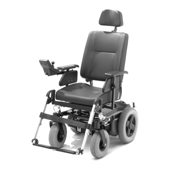
Page 62: Use Of The Parts Lists
Parts lists 6 Use of the parts lists This document is meant as a reference book to be able to order parts for the wheelchair as shown on the front. How to order: To order parts please specify: Serial number (see the identification plate). •... - Page 63 Parts lists Description Suspension arm and drive Battery tray and bridge Suspension and taxi bracket High/low mechanism High/low on carrier Swivel castors Drive wheel Carrier (incl. wheels) Batteries Sedeo seatframe Spring mechanical backrest adjustment Electric back adjustment Mechanical and electric tilt seatframe Mechanical and electric tilt high/low seatframe Mounting bracket and back frame Footplate...
-
Page 64: Version 2011V1
Parts lists 001: Suspension arm and drive • Article number Units Description 05010.5200 Drive right 05010.5300 Drive left No spare part Suspension arm (no longer available) 00000.4023 Cil cap screw inn.zk.M8x80 vz 00000.2003 Washer flat M8 D125A/vz 00000.1702 Locknut M8 D985/8/vz 05010.2783 Guide block 103.00011.000... - Page 65 Parts lists 002: Battery tray and bridge • Article number Units Description 00001.0905 Screw PLV/BZK M8X95 D7991 VZ 05010.0812 Washer 00000.5302 Bearing bush 28X23X16 IGLIDUR 00000.2103 Washer flat 3XD M8 D9021/vz 00000.1702 Locknut M8 D985/8/vz 00001.0902 Screw PLV/BZK M8X20 D7991 VZ 00000.3718 Buttonhead M8X55 VZ 00000.7111...
- Page 66 Parts lists 003: Suspension and taxi bracket • Article number Units Description 00001.0902 Screw PLV/BZK M8X20 D7991 VZ 00000.3708 Buttonhead M8X35 VZ 00000.2103 Washer flat 3XD M8 D9021/vz 05690.0410 Taxi bracket 05690.9010 Taxi bracket set 00000.3713 Buttonhead M8X50 VZ 00000.5403 Wheel anti tip 00000.1702 Locknut M8 D985/8/vz...
- Page 67 Parts lists 004: High/low mechanism • Article number Units Description 00000.3706 Screw M8xP1.25x25L 00000.2203 Spring washer SW8 No spare part H/L reinforcement strip No spare part Bellows-mounting strip, narrow No spare part H/L guiding block No spare part Shears inside 00000.5708 Spacing bush nylon 18X12.3X10 No spare part...
- Page 68 Parts lists 005: High/low on carrier • Article number Units Description 00000.2305 Flat washer M12 PA 00000.2005 Washer flat M12 D125A/vz 00355.0306 Linak motor H/L 00000.4044 Cil cap screw inn zk M6X25 VZ 12.9 00000.2202 Spring washer M6 D127B/VZ No spare part H/L clamping block No spare part H/L mast...
- Page 69 Parts lists 006: Swivel castors • Article number Units Description 05010.2400 Front fork and axle 00000.1702 Locknut M8 D985/8/VZ 00000.2003 Washer flat M8 D125A/VZ 00000.4118 Hex. Bolt M8X120 D931/8.8 VZ 170.00161.000 Wheel complete 05010.4100 BUBA 260/85-108 line profile 05010.4000 BIBA 206/85-108 00001.1463 Sticker tire pressure 3.5 Bar Version 2011v1...
- Page 70 Parts lists 007: Drive wheel • Article number Units Description 05010.4500 Back wheel complete 06010.4200 BUBA 3.00x8 06010.4100 BIBA 3.00x8 05010.4527 00001.1460 Sticker tire pressure 2 Bar Version 2011v1...
- Page 71 Parts lists 008: Carrier (incl. wheels) • Article number Units Description 00000.9008 Insert cap, round 35 black 00000.1750 Locknut M12 D985/8/VZ 00000.2803 Cup spring bl 23X12,2X1 05010.3310 Washer 00000.7604 Key flat 6X6X30 05010.4912 Bush 00000.2104 Washer flat 3XD M10 00001.0601 Lip locking plate DIN463, M10 WHITE 00000.4315 Hex bolt M10X20...
- Page 72 Parts lists 009: Batteries • Article number Units Description 00001.0006 Battery clamp + 00001.0007 Battery clamp - 9002759 Battery (50Ah C5) (60Ah C20) 00355.0126 Autom. fuse 35A + cable 00355.0043 00355.0047 Power cable 00355.0285 Splash bag power module 00000.4036 Cyl cap screw M5X12 00355.0109 DX Power module PM2 80A See: 002: Battery tray and bridge...
- Page 73 Parts lists 010: Sedeo seatframe • Article number Units Description See 011 150.00141.000 Actuator electric back adjustment 02030.3523 Bracket backrest adjustment 00000.2250 Spring washer fluted M8 D137B VZ 00000.1801 Cap locknut M6 D986/VZ 00001.0914 Screw 00000.3519 Adjusting screw cone M8X10 D914 00000.4502 Star knob outs M8X15 BLACK MH 9000156...
- Page 74 Parts lists 011: Spring mechanical backrest adjustment • Article number Units Description No longer available as on drawing. Has been replaced for new type as on Ibis X-Series and Yes-Series. See pos 1 for article number. 1008035 Mechanical backrest adjustment Version 2011v1...
- Page 75 Parts lists 012: Electric back adjustment • Article number Units Description 150.00141.000 Actuator electric back adjustment 00000.3714 Buttonhead M6X25 VZ 05137.2012 Forked shaft 00000.1801 Cap locknut M6 D986/VZ 00000.1602 Hex Nut Low M8 D439B/VZ 001.14080.004 Forked shaft 001.20020.004 Clip Version 2011v1...
- Page 76 Parts lists 013: Mechanical and electric tilting seat frame • Article number Units Description 00000.4021 Cil cap screw inn zk M6X30 VZ 00000.8021 Stauff block PAH BLACK DIA.22 00000.4016 Cil cap screw inn zk M6X25 VZ 02010.7482 Stauff block 05020.0312 Mounting plate 00000.5915 Threaded end VZ M8X80...
- Page 77 Parts lists 014: Mechanical and electric tilt high/low seat frame • Article number Units Description 00000.4021 Cil cap screw inn zk M6X30 VZ 00000.8021 Stauff block PAH BLACK DIA.22 02010.7482 Stauff block 05456.1212 Mechanical tilt adjustment pin 00000.1502 Hex. Nut M8 D934/8/VZ 00000.3706 Screw M8xP1.25x25L 00000.2203...
- Page 78 Parts lists 015: Mounting bracket and back frame • Article number Units Description 9001374 Push frame small XP 00355.4215 2-pole female plug 00000.3542 Adjusting screw + crater M6X8 D916 01502.1223 Insert tube left 05990.0013 Insert tube left for electrical legrest 00000.3501 Adjusting screw BZK M8X10 D913/VZ 05245.0723...
- Page 79 Parts lists 016: Footplate • Article number Units Description See page 83. Version 2011v1...
- Page 80 Parts lists 017: Standard leg rest • Article number Units Description Standard leg rest left See page 83. Standard leg rest right See page 83. 1002515 Standard leg rest upper part left 1002514 Standard leg rest upper part right 01500.1112 Leg rest release lever 01500.2212 Leg rest release spring...
- Page 81 Parts lists 018: Comfort electric leg rest • Article number Units Description Electrical comfort leg rest left See page 83. Electrical comfort leg rest right See page 83. 1003029 Electrical comfort leg rest upper part left 1003028 Electrical comfort leg rest upper part right 1008580 Hinge comfort leg rest 01500.1112...
- Page 82 Parts lists 019: Comfort mechanical leg rest • Article number Units Description Comfort leg rest left See page 83. Comfort leg rest right See page 83. 1002517 Comfort leg rest upper part left 1002516 Comfort leg rest upper part right 1008580 Hinge comfort leg rest 01500.1112...
- Page 83 Parts lists SPARE PARTS SEDEO LEGRESTS AND FOOTPLATES LEGRESTS CALF PLATE AND CALFSTRAP AND TYPE SIZE RIGHT LEFT LEGRESTBRACKET LEGRESTBRACKET, SET 1003561 1003560 1003592 1003579 1003563 1003562 1003593 1003580 01500.9019 01500.9119 140.00071.000 140.00011.000 STANDARD 1003565 1003564 1003594 1003581 1003567 1003566 1003595 1003582 1003569...
- Page 84 Parts lists 020: Lighting • Article number Units Description 6061 Headlight 00355.4225 Tail light orange 00355.4224 Tail light red 00355.4211 Ball light 24V / 2.4W 99009 Tube light 24V 5W 00000.1701 Locknut M6 D985/8/VZ 00000.2002 Washer flat M6 D125A/VZ 00000.4328 Hexagonal tap bolt M4X50 D933 00000.2002 Washer flat M6 D125A/VZ...
- Page 85 Parts lists 021: Lighting • Article number Units Description 05111.1523 Light unit arm left 05111.1782 00000.3710 Buttonhead M5X16 VZ 00355.4200 Rear light red/orange 00355.5540 Ring 00000.3291 Screw BCK/KR M5X12 KS 00000.2101 Washer flat 3XD M5 D9021/VZ 00000.1800 Cap locknut M5 D986/VZ 00355.4240 Flashlight front 00355.5547...
- Page 86 Parts lists 022: Lighting cables • Article number Units Description No spare part No spare part No spare part No spare part No spare part No spare part No spare part No spare part 00355.1080 Lighting cable armrest 00355.1250 LM cable 00355.0023 DX cable 05900.0123...
- Page 87 Parts lists 023: CLAM, LM • Article number Units Description 00355.0201 DX CLAM 00000.5721 Spacer bush 5.2X15X10 PE BLACK 00000.3619 Screw pl verz/kr M3X20 VZ 00355.0205 DX-LM lightning module 00000.3624 Crosshead screw 00000.3616 Screw M5X12 00000.2001 Washer 00000.6504 Pipe clamp back closed 05900.0123 Bracket plate Version 2011v1...
- Page 88 Parts lists 024: Lighting cables • Article number Units Description 00355.1111 Lighting cable 00355.1130 Lighting T piece 00355.1121 Lighting cable 00355.0023 DX bush cable 1 mtr 00000.7101 Ty-rap 23MX 92X2.4 00355.1250 CLAM cable 00355.1250 CLAM cable 00355.1280 Adjusting block 00355.1140 Speed limiter bridge 00355.1201 H/L cable...
- Page 89 Parts lists 025: Armrest • Article number Units Description 05373.9490 Armrest PU left 05040.0223 Armrest upper part left 00000.2201 Spring washer M5 D127B/VZ 00000.3207 Screw BCK/KR M5X20 D7985 00001.0551 00000.1700 Locknut M5 D985/8/VZ 05372.0190 Side cushion 00000.5721 Spacer bush 5.2X15X10 PE BLACK 05372.0223 Strip 02040.0782...
- Page 90 Parts lists 026: Swing-away joystick bracket • Article number Units Description 1009533 Swing-away joystick bracket right 1009536 Swing-away joystick bracket left 00000.9302 Insert cap square 20 black 00000.9301 Insert cap square 15 black 15040.0823 Cylinder joystick bracket 008.00000.191 Sticker clamping 05041.9123 Swing-away bracket + tube for remote right 165.00111.000...
- Page 91 Parts lists 027: DX controller • Article number Units Description 00355.0425 Joystick 16 key incl. cable 00355.0018 Joystick cable 00000.7101 Ty-rap 00000.2201 Spring washer M5 D127B/VZ 00000.3212 Screw M4X25 008.00000.201 Sticker for use consult 008.00000.131 Sticker 10 km/h 008.00000.141 Sticker 8 km/h 008.00000.161 Sticker programmed RWD 008.00000.151...
- Page 92 Parts lists 028: Seat / backrest / calf pad • Article number Units Description Sedeo seat See page 93. 00000.3617 Screw M5X30 00000.6501 Pipe clamp DIA 22 black 220.00121.505 Calf plate standard 220.00141.505 Calf plate small 00000.3206 Screw M5X16 Sedeo backrest See page 94.
- Page 93 Parts lists SPARE PARTS SEDEO SEAT CUSHIONS PROFILED WITH GREY PROFILED MEMORY FOAM SUPPORT W X D MIDDLE BAR 42x50 200.42131.505 1002950 200.40481.517 205.42791.517 46x50 200.42211.505 1002951 200.40561.517 205.42871.517 50x50 200.42291.505 1002952 200.40641.517 205.42951.517 42x54 1001977 1002953 1001997 1002006 42x58 1001978 1002954 1001998...
- Page 94 Parts lists SPARE PARTS SEDEO BACKRESTS PROFILED WITH GREY WITH LUMBAR PROFILED EXTRA SOFT SUPPORT W X D MIDDLE BAR 42x52 207.20031.505 1002974 215.20031.505 207.20211.520 46x52 207.20051.505 1002975 215.20051.505 207.20231.520 50x52 207.20071.505 1002976 215.20071.505 207.20251.520 42x56 1002143 1002977 1002161 1002179 42x60 1002144 1002978...
- Page 95 Parts lists 029: Headrest • Article number Units Description 222.00151.505 Headrest type 4, small mode, black Sellaskin 222.00131.505 Headrest Type 3, Flexible, black Sellaskin 222.00111.505 Headrest Type 2, Large, black Sellaskin 00000.3206 Screw bck/kr M5X16 D7985 02193.0023 Metal Section Headrest. Standard Adjustable 02194.0023 Metal Section Headrest.
- Page 96 Spring washer M5 D127B/VZ 00000.4038 Cil cap screw. inn. zk M5X10 VZ 00001.1328 Sticker automatic fuse No spare part 00001.1334 Logo Booster Puma Kinetic 00001.1330 Reflector sticker red 00001.1352 Sticker freewheel right See: 002: Battery tray and bridge Version 2011v1...
- Page 97 Version 2011v1...
- Page 98 Parts lists Version 2011v1...
Need help?
Do you have a question about the PUMA KINETIC and is the answer not in the manual?
Questions and answers