Xantrex GT 2.5-DE, GT 3.8-DE, GT 2.8-S Manuals
Manuals and User Guides for Xantrex GT 2.5-DE, GT 3.8-DE, GT 2.8-S. We have 2 Xantrex GT 2.5-DE, GT 3.8-DE, GT 2.8-S manuals available for free PDF download: Owner's Manual
Xantrex GT 2.5-DE, GT 3.8-DE, GT 2.8-S Owner's Manual (92 pages)
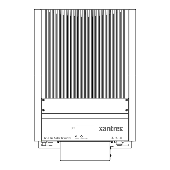
Grid Tie Solar Inverter
Table of Contents
Advertisement
Xantrex GT 2.5-DE, GT 3.8-DE, GT 2.8-S Owner's Manual (84 pages)
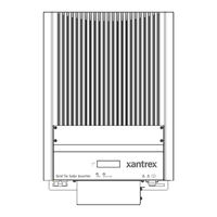
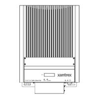
Grid Tie Solar Inverter
Table of Contents
Advertisement