Teka CG.1 4G Installation Instructions Manual

Teka CG.1 4G Installation Instructions Manual

Glass gas hobs recommendations for use and maintenance

Advertisement

INSTALLATION INSTRUCTIONS
AND RECOMMENDATIONS FOR USE AND MAINTENANCE
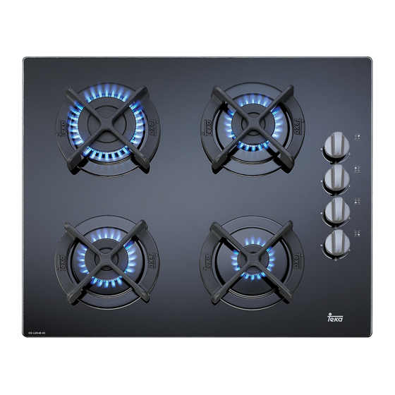
GLASS GAS HOBS
EINBAU-ANLEITUNG
UND EMPFEHLUNGEN FÜR GEBRAUCH UND INSTANDHALTUNG
GAS-KOCHFELDER AUF GLAS
INSTRUCTIONS POUR L'INSTALLATION
ET RECOMMANDATIONS D'UTILISATION ET D'ENTRETIEN
PLAQUES DE CUISSON
CG.1 4G / CG.1 3G 1P
CG Lux-60 4G / CG Lux-70 4G / CG Lux-70 4G AI AL
CG Lux-70 5G / CG Lux-60 4G Al AL / CG Lux-70 5G Al AL
CG Lux-70 5G AI TR AL / CG Lux-70 5G TR / CGC 4G
CGC 4G AI AL / CG Lux-75 2G AI TR AL / CG Lux-86 3G AI TR AL
CG Lux-60 4G AI / CG Lux-70 4G AI / CG Lux-70 5G AI
CG Lux-70 5G AI TR / CG Lux-75 2G AI TR / CG Lux-86 3G AI TR
VR 90 4G AI TR AL / VR 90 4G AI TR

Advertisement

Table of Contents
loading
Need help?

Need help?

Do you have a question about the CG.1 4G and is the answer not in the manual?

Questions and answers

Summary of Contents for Teka CG.1 4G

  • Page 1 ET RECOMMANDATIONS D’UTILISATION ET D’ENTRETIEN PLAQUES DE CUISSON CG.1 4G / CG.1 3G 1P CG Lux-60 4G / CG Lux-70 4G / CG Lux-70 4G AI AL CG Lux-70 5G / CG Lux-60 4G Al AL / CG Lux-70 5G Al AL...
  • Page 3: Table Of Contents

    Contents / Inhalt / Table des Matières Introduction Page 5 Präsentation Seite 5 User Guide Hinweise zum Gebrauch Installation Einbau Positioning the hobs Einbauort für die Kochfelder Positioning the oven Einbauort für den Ofen Anchoring the hob Verankerung des Kochfelds Connecting the gas Gasanschluss Connecting the electricity...
  • Page 4 Présentation Page 5 Guide d’utilisation Installation Logement des tables de cuisson Logement du four Ancrage de la table de cuisson Raccordement au gaz Branchement électrique Adaptation du gaz Informations techniques Dimensions et puissances Caractéristiques techniques Utilisation et entretien Conditions spéciales avant la mise en marche Allumage des brûleurs Allumage des plaques électriques...
  • Page 5: Introduction

    Introduction / Einführung / Présentation CG.1 4G CG.1 3G 1P 1 Semi-rapid burner 1,500 Kcal/h -1.75 kW. 1 Rapid hotplate 1500 W., ø 145 mm. 2 Auxiliary burner 860 Kcal/h - 1 kW. 2 Auxiliary burner 860 Kcal/h - 1 kW.
  • Page 6 CG-Lux-60 4G / CG Lux-60 4G Al AL / CG Lux-60 CGC 4G / CGC 4G AI AL 4G AI 1 Rapid burner 2,580 Kcal/h - 3 kW. 1 Rapid burner 2,580 Kcal/h - 3 kW. 2 Semi-rapid burner 1,500 Kcal/h -1.75 kW. 2 Semi-rapid burner 1,500 Kcal/h -1.75 kW.
  • Page 7 CG-Lux-70 5G / CG Lux-70 5G Al AL / CG Lux -70 CG-Lux-70 5G TR / CG Lux-70 5G AI TR AL / CG Lux -70 5G AI TR 5G AI 1 Rapid burner 2,580 Kcal/h - 3 kW. 1 Rapid burner 2,580 Kcal/h - 3 kW. 2 Semi-rapid burner 1,500 Kcal/h -1.75 kW.
  • Page 8 CG-Lux-70 4G / CG-Lux-70 4G AI AL / CG-Lux-75 2G AI TR AL / CG Lux-75 2G AI TR CG Lux -70 4G AI 1 Triple crown burner 3,010 Kcal/h - 3.5 kW. 1 Rapid burner 2,580 Kcal/h - 3 kW. 2 Triple crown burner 3,010 Kcal/h - 3.5 kW.
  • Page 9 CG-Lux-86 3G AI TR AL / CG Lux-86 3G AI TR VR 90 4G AI TR AL / VR 90 4G AI TR 1 Triple crown burner 3,010 Kcal/h - 3.5 kW. 1 Triple crown burner 3.010 Kcal/h - 3,5 kW. 2 Triple crown burner 3,010 Kcal/h - 3.5 kW.
  • Page 10: User Guide

    Likewise, any internal work on the hob should only be done by TEKA’s Before installing and using it, we would technical staff, including the change of the ask that you read this Manual carefully and flexible supply cable of the appliance.
  • Page 11: Installation

    11 will be cut into the unit’s worktop or stove. In the packaging of the models CG.1 4G and CG.1 3G 1P, there is a tem- plate included that is for use in sizing the space for these two hob models.
  • Page 12: Positioning The Oven

    This operation should be done before fastening the clamps to the hob. fig. 12 20 mm 30 mm 40 mm Mod.: CG Lux-60 y CGC 4G Mod.: CG.1 3G 1P y CG.1 4G Mod.: CG Lux-70 Seal Mod.: CG Lux-75 Worktop Mod.: CG Lux-86 Screw Mod.: VR 90 4G...
  • Page 13 30 mm thick worktops 40 mm fig. 13 On models CG.1 4G and CG.1 3G 1P, the clips should be fixed as shown in figure 13, depending on the thickness of the worktop. With the hob model CGC 4G, when the...
  • Page 14 ATTACHING THE HOB TO THE OVEN 6 Complete the definitive positioning of the OR THE CONTROL PANEL oven, ensuring that the cardan telescopic shafts are firmly in position and that the The hob has four cardan telescopic shafts telescopic pipes are well-aligned when for this purpose.
  • Page 15: Connecting The Gas

    If the check is done using air, care should be taken that This cooker includes caps for all TEKA the test pressure is no more than 200 ovens except models RT-600 and RT-800.
  • Page 16: Gas Conversion

    When the injectors have been changed, burners’ minimums has not been carried this is how to adjust the minimums: out by TEKA’s official personnel. Hobs CG.1 4G, CG.1 3G 1P, CGC 4G and CGC 4G AI AL 1 Turn the burners on to their minimum.
  • Page 17 Table 1 Burner Family Second Third Group H Group E+ Group 3+ Triple crown 135 T 135 T Rapid 116 Y 116 Y Semi-rapid 97 Z 97 Z Auxiliary 72 X 72 X Ø injector expressed in 1/100 mm.
  • Page 18: Technical Information

    Technical Information Dimensions and powers CG Lux-60 VR 90 4G Models CG.1 4G CG.1 CG Lux-60 CGC 4G CG Lux-70 4G AI AI TR 3G 1P AI AL CG Lux-60 VR 90 4G 4G AI AL AI TR AL Dimensions in mm...
  • Page 19 Models CG Lux-70 CG Lux-70 CG Lux-70 CG Lux-75 CG Lux-86 4G AI 5G AI 5G AI TR 2G AI TR 3G AI TR CG Lux-70 CG Lux-70 CG Lux-70 CG Lux-70 CG Lux-70 CG Lux-75 CG Lux-86 4G AIAL 5G AI AL 5G AI TR AL 5G TR...
  • Page 20: Technical Data

    G-31 (Kg/h) 0,21 0,13 0,07 0,24 CG Lux-60, CG Lux-70, 0,77 0,47 0,33 CGC 4G, CG.1 4G, CG.1 3G 1P 1,55 0,77 0,47 VR 90 4G, CG Lux-70 5G TR 0,33 CCR CG Lux-75 and CG Lux-86 1,55 0,47 Performance >52...
  • Page 21: Use And Maintenance

    * Turn on the gas at the mains or turn the gas cylinder’s tap. On hob models CGC 4G, CG.1 4G and * Press down the burner control. CG.1 3G 1P (See fig. 18). * Keeping the burner control pressed...
  • Page 22 * Set the control to the position required. fig. 19 The ignition (ceramic and electrode) should be cleaned regularly and care- fully in order to avoid ignition problems. Check, too, that the grooves in the bur- ners have not become obstructed. Use flat-bottomed pans and check that they sit squarely on the grid, so that when food boils the pan does not slip (do not use...
  • Page 23: Turning On The Electric Hotplates

    - to dry it out, turn the hot- plate on with no pan on it for five minutes at switch position 2. TEKA Industrial S.A. reserves the right to ‘Hotplate in operation’ indicator alter its appliances in any way it deems...
  • Page 24: Safety Sistem Components

    fig. 22 Anti-accidental turn system on gas controls On models without the safety sys- tem (without the gas cut-off device), the gas taps are equipped with a mechanical system that prevents the controls from being freely turned from the off position to the on position (and, therefore, prevents any accidental escape of gas from the bur- ners) if the control has not previously...
  • Page 25: The Burners

    If this anomaly and disconnect the electricity. Then con- persists, contact the Technical Assistan- tact TEKA’s Technical Service. ce Service in order that the main air inlet * Do not use the glass surface as a stora- can be adjusted or the gas supply pipe ge area.
  • Page 26: Of The Hotplates

    inspected by specialised Technical Service NEVER USE ELECTRIC HOTPLATES personnel at least once every 4 years. WITHOUT A PAN. Maintenance of the electric Note: hotplates (CG.1 3G 1P) Any alteration or adjustment needed by the appliance should be made by aut- Disconnect the appliance from the electric horised technical personnel.
  • Page 27 When cleaning the glass, the degree of rust removers or sponges or scourers soiling should be taken into considera- with a hard surface. tion, and the following guidelines follo- * Do not slide pans over the glass, as they wed: can cause scratches.
  • Page 28 * When cleaning the appliance with the burners removed, care should be taken not to allow liquid or other objects to get into the bend of the injector holder. * When cleaning, do not use products that can harm aluminium, such as soda, oil, etc.
  • Page 29: Reminder

    Reminder Do not use small pans on large burners, or the flame will spread. Match pans to burners to make best use of the heat. Do not place the pan away from the centre of the burner. Place the pan properly, in the middle of the burner. Do not use utensils that reflect a lot of heat down- wards directly onto the grid.
  • Page 30: If Something Doesn't Work

    If something doesn’t work Before calling the Technical Service, please make the following checks: Fault Possible cause Possible solution Neither the hotplates nor the pilot lights are working The cable is not Connect the cable connected to the mains to the mains There is no spark when the automatic ignition control is pressed There is no current...

Table of Contents