DriSteem STS Installation, Operation And Maintenance Manual
Steam-to-steam humidifier
Hide thumbs
Also See for STS:

Subscribe to Our Youtube Channel
Related Manuals for DriSteem STS


Summary of Contents for DriSteem STS
- Page 1 IMPORTANT: Read and save these instructions. ® S TS S t e a m- t o- S t e a m H um i di f i e r In stallation, Op eration , a nd Mainten ance Man u al...
- Page 2 W A R N I N G ! Read this manual before installing. Leave manual with product owner. Disconnect electrical power before installing supply wiring. Contact with energized circuits can cause severe personal injury or death as a result DRI-STEEM ® technical support of electrical shock. 800-328-4447 This product must be installed by qualified HVAC and electrical...
-
Page 3: Table Of Contents
STS humidifier ........ -
Page 4: Overview
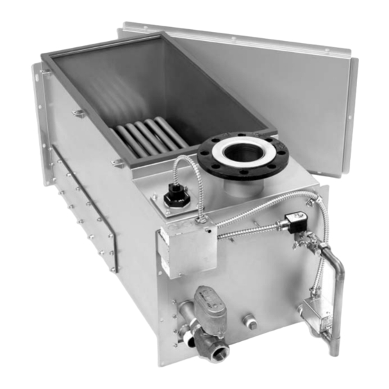
The standard water STS humidifier requires water conductivity of at least 100 μS/cm (2 grains/gallon) to operate. It will not operate with water treated by reverse osmosis or deionization processes. However, STS humidifiers are available for use with these water types. See below. Deionized water models (STS-DI) The STS-DI, shown below, is designed specifically for use with deionized or reverse osmosis water. -
Page 5: Dimensions
Overview Figure 5-1: Dimensions, STS models 25, 50, 100, 200 and 400 (with copper or stainless steel heat exchangers) Front view Side view 5/16" dia. (M8) mounting holes OM-931 OM-932 Note: See the dimension tables on the next page. Figure 5-2:... - Page 6 3.75 Notes: * Add 23.5" (597 mm) to overall height when STS is mounted on four support legs. Add 22.5" (572 mm) to overall height when STS is mounted on two H-legs. Table 6-2: STS dimensions with stainless steel heat exchangers...
-
Page 7: Capacities And Weights
400C 800C 1275 1500 1600 Notes: * Steam pressure at connection to the STS steam valve (valve provided by DRI-STEEM) Table 7-2: Output capacities for STS models with stainless steel heat exchangers Steam pressure* STS model 5 psi 34 kPa... -
Page 8: Installation
Installation When selecting the location of the humidifier, consider the following: Figure 8-1: Hose connection aximum ambient temperature for control cabinet is 104 °F (40 °C). primarily top, left side, and front (see clearance recommendations below) hose, tubing, or piping sate piping, and optional equipment (see Page 30 of this manual) DC-1455 sate return piping... - Page 9 2" 1½" 2" 3" 4" 5" 6" Table 9-2: STS connection sizes Description Connection size Water makeup (fill) ¼" pipe thread (DN8) ¾" (DN20) for standard water models 25 through 100 Drain (and all DI water models) 1" (DN25) for standard water models 200 through 800 Varies with capacity and dispersion type.
-
Page 10: Support Legs
(STS/STS-DI models 25, 50, 100 only) Secure threaded rod to an overhead structure that is strong enough to support the operating weight of the STS/STS-DI humidifier and field installed piping, plus the weight of the control cabinet if it is mounted on the humidifier. -
Page 11: H-Legs
Figure 11-2: (STS and STS-DI models 200, 400, 800 only) H-legs While the STS and STS-DI tank is securely held in the air, attach front and rear supports using the supplied " (M10) bolts, nuts, plished by having the bolts slightly loose as the tank is lowered to the floor. - Page 12 (100 mm u 50 mm timbers) with center line spaced at dimension Support shown in the table below. legs – STS 25: lag bolt (coach screw) both horizontal 2 u 4s (100 mm u 50 mm timbers) to two vertical studs Wall brackets (16"...
-
Page 13: Weather Cover
Weather cover exploded view resistant and designed to protect an STS Top rear panel unit from rain and sun. The STS weather cover has been tested and approved by ETL Top front panel Testing Laboratories, Inc., and is listed to... - Page 14 Installation Note: The weather cover encloses the STS humidifier to protect it from wind, sun, and rain. The weather cover is fully assembled at the For information about the STS outdoor enclosure (a weather-tight enclosure with Testing Laboratories, Inc., and is listed to UL Standard 1995 and access doors, supplemental heating and cooling fan[s]), see the following pages.
-
Page 15: Outdoor Enclosure
2. There are four knockouts located on the right and left side of the enclosure. Knockout sizes are 1½" (hole dia. 50 mm) for STS models 25-100, and 2"... - Page 16 Installation Figure 16-1: STS outdoor enclosure, top view Valve access door: Valve access door Pipe chase extending 1" (25 mm) above enclosure floor Optional steam outlet (exits enclosure through pipe chase) Valve section heater Intake ventilation fan Enclosure drain Control panel...
- Page 17 STS-200 1050 1650 STS-400 1125 1450 STS-800 1225 2250 1021 Note: * Includes humidifier Table 17-2: STS outdoor enclosure connection sizes STS or STS-DI model number Description 25-100 200-800 Water makeup (fill) Drain Condensate return Steam outlet See STS catalog...
- Page 18 2. Ensure that water lines are protected from freezing conditions. thermostat with a remote sensor on the fill line to cut power to the STS and safety valves to stop fill water to the STS and drain the fill piping when the temperature is below freezing.
- Page 19 Legs unit. (STS 25-100 only) if forks extend across the entire unit. Forks that do not extend across the entire unit could cause tipping resulting in unsafe conditions or damage to the unit.
- Page 20 Installation Important note about STS outdoor enclosure installation base frame and/or special lifting lug hooks installed on the unit. All lifting operations must be accomplished with a load spreader of sufficient width to ensure that the lifting cables clear the side leading to the humidifier.
- Page 21 Installation pipe chase is provided to maintain proper pressure within the enclosure in the event that this opening is not utilized. However, it is recommended that this pipe chase be used for both the supply water piping and drain piping, in which case the pipe chase cover should be removed.
- Page 22 Installation Note: drain from the enclosure through this drain. If your STS humidifier uses a LW417 controller, the aquastat option must be control, a keypad with ® 3 purchased to provide freeze protection. standard 5' (1.5 m) cable ships mounted to the subpanel in the outdoor enclosure.
- Page 23 Installation Operation When power is applied to the outdoor enclosure: (10 °C), the enclosure strip heaters are powered up. The humidifier is not allowed to operate unless the temperature inside the enclosure is equal to or greater than 35 °F (2 °C). The strip heaters will power down when the temperature inside the enclosure reaches 50 °F (10 °C).
-
Page 24: Drain
Installation Drain piping The drain line piped from the humidifier must be run to an approved sanitary waste or suitable drain. If nonmetallic pipe or vapor hose is used, it must be rated for 212 °F (100 °C) minimum continuous operating temperature. of the drain piping exceeds 10' (3 m), increase the pipe size to 1¼"... - Page 25 (203 mm), allowing the tank to sit closer to the floor. Water supply piping The STS and STS-DI humidifier has a 1" (25 mm) internal air gap to prevent back siphoning into a potable water system. However, some governing codes may require additional protection such as a vacuum breaker or backflow preventer.
- Page 26 552 kPa) for all STS and STS-DI models except the STS-DI 800. The STS-DI 800 supply water pressure range must be 60 psi to 80 psi (414 kPa to 552 kPa). An optional fill assembly is available to allow a minimum water pressure of 25 psi (172 kPa) at an additional cost.
-
Page 27: Standard Water, One Heat Exchanger
Installation Figure 27-1: Field piping overview for STS models 25, 50, 100, 200, 400 (models with one heat exchanger) Shock arrester recommended Water supply shut-off valve, by installer to reduce water hammer, by installer If water piping to humidifier is nonmetallic, we recommend a 2"... -
Page 28: Di Water, Two Heat Exchangers
No additional backflow prevention is required; however, governing codes prevail. these models is available for water pressures between 25 psi and 80 psi (172 kPa and 552 kPa). All other STS models operate with water pressure between 25 psi and 80 psi (172 kPa and 552 kPa). - Page 29 The strainer will prevent particulate from collecting at the solenoid valve seat. If the STS-DI humidifier is supplied with tap water, the float valve assembly will become clogged and run without water. More on the next page ▶...
-
Page 30: Steam Supply
The figure below shows piping of an STS unit from an overhead steam supply main with condensate returned to a vented gravity the branch feeding the steam valve of the STS. Failure to install this trap will cause water hammer, which could damage the STS heat exchanger. -
Page 31: Wiring
105 °C environment. The wiring from the warranty. control cabinet to the humidifier must be rated for 105 °C. All STS humidifiers have a 120-volt, single phase electrical supply. Verify current characteristics and capacity requirements against those listed on the name plate. - Page 32 The control cabinet should be mounted in a location convenient for directive can damage sensitive electronic service with a minimum of 36" (914 mm) clearance in front of the components and void your DRI-STEEM door. warranty. The installer is responsible for making electrical connections at the power terminals.
- Page 33 18-gauge (1 mm ) plenum rated, shielded (screened), twisted pair together on external components are not wire with a bare drain wire for grounding. covered under your DRI-STEEM warranty. Review information and diagrams before Grounding requirements proceeding. The approved earth ground must be made with solid metal-to-metal connections and must be a good conductor of radio frequency inter- ference (RFI) to earth (multistranded conductors).
-
Page 34: Humidistat And Transmitter Placement
Installation Humidistat and transmitter locations are critical Humidistat and humidity transmitter locations have a significant you do not interchange duct and room humidity devices. Room humidity devices are calibrated with zero or little airflow; whereas duct humidity devices require air passing across them. See the following recommendations and the locations in Figure 34-1. -
Page 35: General Instructions
In this document: required for non-wetting to occur. If you have questions about absorption non-wetting distances, see the non-wetting tables in installation, Pages 36-38 the STS catalog, available for viewing, printing or ordering at www.dristeem.com instructions, Pages 40-44 ® installation instructions,... -
Page 36: Interconnecting Piping Requirements
Installation Connecting humidifier to dispersion assembly with vapor hose W A R N I N G ! Dispersion tube, vapor hose, tubing, or hard maintain a minimum pitch of 2"/ft (15%) back to the humidifier. pipe can contain steam, and surfaces can be hot. - Page 37 ††† When using vapor hose, use DRI-STEEM vapor hose for best results. Field-supplied hose may have shorter life and may cause foaming in the evaporating chamber resulting in condensate discharge at the dispersion assembly. Do not use vapor hose for outdoor applications.
-
Page 38: Drip Tee Installation
STS humidifier To dispersion device Tubing or pipe drip tee, by installer. 6" (150 mm) DRI-STEEM part numbers for 304 stainless steel in-line tees: minimum 8" (200 mm) ¾" (DN20) minimum 1" (25 mm) air gap Funnel or floor drain... -
Page 39: Overhead Installation
(see figure below). It is advisable to terminate the drain above an open floor drain. The overflow from the STS should be piped separately to a floor drain. Do not drain the STS directly into the drip pan. -
Page 40: Single Tube And Multiple Tube
Installation I m p o r t a n t : Installation Failure to follow the recommendations in installing single tube and multiple tube dispersion assemblies. this section can result in excessive back pressures on the humidifier. This will result in unacceptable humidification system applications. - Page 41 Do not 3/8" (M10) insulate vapor hose. Pitch* mounting nut Secure and seal duct Tube pitch 2"/ft STS humidifier escutcheon plate (15%) 90° long sweep or Maximum capacity of two 45° elbows dispersion tube: 28.4 lbs/hr (12.9 kg/h) 56.8 lbs/hr (25.8 kg/h)
- Page 42 Installation Figure 42-1: Single tube dispersion with condensate wasted to floor drain Maximum capacity of dispersion tube: Duct Secure and seal Vapor hose, tubing or escutcheon plates pipe. Insulate tubing and hard pipe to reduce steam loss. Do not insulate vapor hose. 3/8"...
- Page 43 5" (127 mm) water seal 6" (152 mm) ½" (DN15) O.D. condensate drain minimum tube, pitch ¼"/ft (2%) STS humidifier H2 (see Table 27-1) ¾" (DN20) condensate return connection (on face plate) Condensate drain tube, by installer, ¾" DN20 minimum.
- Page 44 Mounting escutcheon plates nut, 3/8" (M10) Pitch* 90° long sweep or two 45° elbows 6" Pitch tube toward STS humidifier (152 mm) drain "/ft (1%) ¼" pipe thread (DN8) Water seal ½" (DN15) O.D. condensate 5" (127 mm) drain tube, pitch ¼"/ft (2%) Condensate drain tube provided by installer, ¾"...
-
Page 45: Rapid-Sorb
Installation I m p o r t a n t : General Rapid-sorb installation instructions Failure to follow the recommendations in this section can result in excessive back this manual. pressures on the humidifier. This will result in unacceptable humidification system of all Rapid-sorb components with packing list. - Page 46 Installation I m p o r t a n t : Before marking and drilling holes in the duct or air handler, refer to ALL pitch requirements for the Rapid-sorb assembly you received (see the table on Page 46). The size, quantity, and location of penetrations are determined by the specific dimensions and configuration of the Rapid-sorb assembly you received.
- Page 47 Open drain required. air gap Locate air gap only in spaces with adequate temperature and air Note: STS humidifier movement to absorb flash steam; * Pitch vapor hose, tubing, or otherwise, condensation may form on pipe toward Rapid-sorb: nearby surfaces. Refer to governing –...
- Page 48 Installation Assembly and installation instructions for a Rapid-sorb installed with header outside the duct (continued) ip coupling on the header stub or dispersion tube so the O-ring is resting on the face of the tubing. lubricant. 4. Position the flange of the L-bracket so it is upstream of the tubes when the assembly is raised and fastened into position.
- Page 49 Installation Assembly and installation instructions for a Rapid-sorb installed Note: with header outside the duct (continued) See Page 52 for steam supply and condensate drain line connection – The dispersion tube and slip coupling must be fully instructions. engaged on to the header stub for the O-rings to provide a seal.
- Page 50 Open drain required. air gap Locate air gap only in spaces with adequate temperature and air Note: STS humidifier movement to absorb flash steam; * Pitch vapor hose, tubing, or otherwise, condensation may pipe toward Rapid-sorb: form on nearby surfaces. Refer to –...
- Page 51 Installation Assembly and installation instructions for a Rapid-sorb installed with header inside the duct (continued) lubricant. 5. Allow the dispersion tubes to rest against the bottom of the duct. 6. Position the flange of the L-bracket so it is upstream of the tubes when the assembly is rotated into position.
- Page 52 Installation Steam supply connections to the Rapid-sorb header 1. Connect the steam supply interconnecting piping from the humidifier to the Rapid-sorb. The steam supply piping requires a minimum of 1/8"/ft (1%) pitch toward the header. 2. If multiple humidifiers are supplying one Rapid-sorb, a multiple steam supply connector is provided.
-
Page 53: Area-Type Fan
Installation Area-type fan dispersion Table 53-1: The table on the following page lists the Area-type steam minimum Area-type electric fan specifications rise, spread, and throw nonwetting dimensions. Surfaces or objects Motor 120 V, 50/60 Hz located within this minimum dimension can cause condensation and dripping. - Page 54 Installation Table 54-1: Area-type (evaporative steam) minimum non-wetting distances* 60 °F (16 °C) Maximum steam 30% RH 40% RH 50% RH capacity Rise Spread Throw Rise Spread Throw Rise Spread Throw lbs/hr kg/h 10.0 10.0 10.0 12.0 12.0 12.0 13.0 14.0 14.0 13.0...
-
Page 55: Operation
After the system is installed and connected properly, you can begin perform the start-up procedure. start-up procedures. Start-up and checkout procedures 1. Verify that the STS humidifier, controls, piping, electrical connec- tions, steam supply, and dispersion unit(s) are installed according to the following: Vapor-logic Installation and Operation Manual –... - Page 56 Operation LW417 electronic water level control option (for standard water Figure 56-1: units only) Water level control for DI/RO water systems The LW417 is a custom microprocessor-based water level controller humidifiers. The features of Supply water connection this controller are: control (for standard water units) Float rod Float ball...
- Page 57 Operation Automatic drain and flush Figure 57-1: This control module contains an integral electronic timer that Water level control for standard tracks the humidifying time of the unit. When this accumulated water systems time reaches what has been set in the timer, the drain/flush cycle is activated.
- Page 58 Operation End-of-season drain The end-of-season drain feature drains the tank after 72 hours of no system demand to minimize microbial growth inside the humidi- fier. When there is a demand for humidity, the tank fills and the unit runs when the operating level is reached. Onboard diagnostics When the green “Power”...
-
Page 59: Maintenance
Maintenance The best way to determine how often your particular system needs Table 59-1: maintenance is to remove the tank cover and inspect it for mineral Skim time settings deposits after three months of duty. Potable water carries a variety Switch of minerals and other materials in a mix that varies from location to Skim time... -
Page 60: Standard Water Models
The De-scaling Solution also cleans surfaces unreachable by hand (STS humidifiers) or the inlet hot liquid supply (LTS scraping. humidifiers). DRI-STEEM's Humidifier De-scaling Solution Models with a standard drain valve and Vapor-logic3 controller:: is the only approved cleaner/de-scaler for –... - Page 61 Maintenance Safety IMPORTANT: When performing maintenance on the STS humidi- fier (after the tank has cooled down and drained), (Vapor-logic only). position. Inspection and maintenance Annually (also recommended when maintenance is performed) off to verify they are functioning. These include: –...
- Page 62 Maintenance Cleaning the skim overflow port d drain from the skimmer drain pipe after each fill cycle. This should be verified visually by a weekly inspection. a long tool such as a screwdriver. mineral accumulation, – Remove the water seal piping from the humidifier and flush out.
-
Page 63: Di Water Models
Maintenance STS-DI water requirements erification that water processing equipment is operating correctly. The presence of chlorides in improperly processed DI water eventually causes pitting and failure of the warranty does not cover damage caused by chloride corrosion. Cool down humidifier Before performing any maintenance, allow the tank to cool down. - Page 64 Maintenance Inspection and maintenance Annually (also recommended when maintenance is performed) off to verify they are functioning. These include: – High limit switch – Airflow proving switch not shut off, there may be particulate on the valve seat, or the stopper may be worn and need replacing.
-
Page 65: Outdoor Enclosure
Maintenance CAUTION: outdoor enclosure electrical service door. Always shut off electrical service disconnect prior to working on the humidifier. annually. maintenance manual for complete maintenance of your humidifier. Table 65-1: Outdoor enclosure troubleshooting guide Symptom Possible cause Recommended action Fans not operating Check for power to outdoor enclosure. -
Page 66: Troubleshooting
Troubleshooting Table 66-1: STS humidifier Possible causes Actions Issue Humidifier will not heat or LW417 troubleshooting guide. Humidifier will not fill supply pressure. coil. Audible click should be heard as solenoid operates. Humidifier does not stop filling stops, verify tank ground. -
Page 67: Lw417 Controller
Troubleshooting Table 67-1: LW417 controller Module indicating lights Issue Possible causes Actions Full Ready Drain water Humidifier will not heat transformer circuit breaker. Humidifier will not heat – "ready water" indicator supply closed "off" but enough water in tank indicator remains "off," replace module. 24 VAC common "white"... -
Page 68: Replacement Parts
Replacement parts Figure 68-1: Tank replacement parts OM-946... - Page 69 Heat exchanger, STS Consult factory Cleanout plate, STS-25 165481-001 Cleanout plate, STS-50/100 165481-002 Cleanout plate, STS-200/400/800 165481-003 Cleanout plate gasket, STS-25 308015-001 Cleanout plate gasket, STS-50/100 308015-002 Cleanout plate gasket, STS-200/400/800 308015-003 Fill assembly Consult factory Float fill assembly, STS-25/50/100 505315 Float fill assembly, STS-200/400/800...
-
Page 70: Control Cabinet
OM-949 Table 70-1: Control cabinet replacement parts* Description Part no. Control cabinet, 12 x 12 407100-003 Subpanel, STS 165720-002 Control board, Vapor-logic 408941-001 Control board, LW417 408632 Transformer, 120V to 24V 408965-001 Terminal block... -
Page 71: Outdoor Enclosure
Replacement parts Figure 71-1: Outdoor enclosure replacement parts OM-953 Table 71-1: Outdoor enclosure replacement parts Number in drawing Description Part number 500W strip heater 405800-052 1100W strip heater 405800-053 Cooling fan 405800-068 Gasket, door or roof 308005-010* Stat, high limit 405800-065 Stat, low limit 405800-066... - Page 72 Expect quality from the industry leader Two-year Limited Warranty For more than 40 years, DRI-STEEM has been leading the industry with creative and products will be free from defects in materials and workmanship for a period of two (2) years after installation or twenty-seven (27) months from the date reliable humidification solutions.
Need help?
Do you have a question about the STS and is the answer not in the manual?
Questions and answers