Dexter Laundry T-400 On-Premise Operator's Manual
Industrial washer model t-400 on-premise v-series control
Hide thumbs
Also See for T-400 On-Premise:
- Parts & service manual (87 pages) ,
- Operator's manual (68 pages) ,
- Operator's manual (66 pages)
Table of Contents
Advertisement
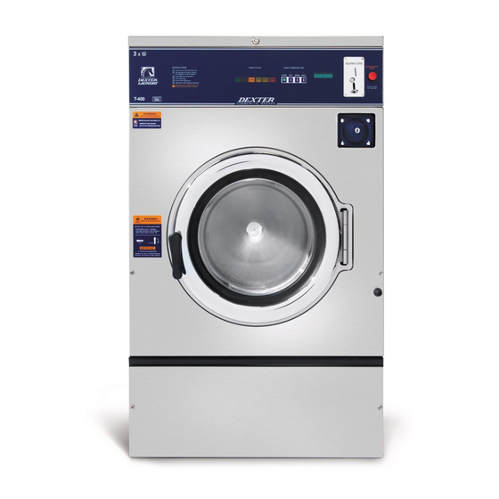
INDUSTRIAL WASHER
MODEL T-400 ON-PREMISE
V-SERIES CONTROL
WARNING - THIS WASHER IS EQUIPPED WITH DEVICES AND FEATURES RELATING TO ITS SAFE
OPERATION. TO AVOID INJURY OR ELECTRICAL SHOCK, DO NOT PERFORM ANY SERVICING UNLESS
QUALIFIED TO DO SO.
IT IS THE RESPONSIBILITY OF THE OWNER TO CHECK THIS EQUIPMENT ON A FREQUENT
BASIS TO ASSURE ITS SAFE OPERATION.
A machine should NOT be allowed to operate if any of the following occur:
-
Excessively high water level.
-
If machine is not connected to a properly grounded circuit.
-
If the door does not remain securely locked during the entire cycle.
-
Vibration or shaking from an inadequate mounting or foundation.
WARNING - SAFETY PRECAUTIONS
Always shut off power and water supply before servicing.
-
Do not overload the washer.
-
Do not open door when cylinder is in motion or it contains water.
-
Do not bypass any safety devices of this washer.
-
Do not use volatile or flammable substances in or near this washer.
-
Keep all panels in place. They protect against shock and injury and add rigidity to the washer.
-
PREVENTIVE MAINTENANCE REQUIREMENTS
DAILY
Check that the loading door remains securely locked and cannot be opened during an entire
-
cycle.
Check the water connections for leaks.
-
Clean the top, front, and sides of the cabinet to remove residue.
-
Clean the soap dispenser and lid and check that all dispenser mounting screws are in-place and
-
tight.
Check the drain valve for leaking and that it opens properly.
-
Check the loading door for leaks. Clean the door seal of all foreign matter.
-
Leave the loading door open to aerate the washer when not in use.
-
QUARTERLY
Make sure the washer is inoperative by switching off the main power supply.
-
Check the V-belts for wear and proper tension.
-
Clean lint and other foreign matter from around motor.
-
Check all water connections for leaks.
-
Wipe and clean the inside of the washer and check that all electrical components are free of
-
moisture and dust.
Remove and clean water inlet hose filters. Replace if necessary.
-
Check anchor bolts. Retighten if necessary
-
IMPORTANT: Replace any and all panels that were removed to perform daily and/or quarterly
maintenance.
8514-238-001 REV PR page 1
OPERATOR'S MANUAL
INSTALLATION & OPERATION
INSTRUCTIONS
Please read this information and retain for reference.
Advertisement
Table of Contents

Related Manuals for Dexter Laundry T-400 On-Premise


Summary of Contents for Dexter Laundry T-400 On-Premise
- Page 1 INDUSTRIAL WASHER MODEL T-400 ON-PREMISE V-SERIES CONTROL OPERATOR’S MANUAL INSTALLATION & OPERATION INSTRUCTIONS Please read this information and retain for reference. WARNING - THIS WASHER IS EQUIPPED WITH DEVICES AND FEATURES RELATING TO ITS SAFE OPERATION. TO AVOID INJURY OR ELECTRICAL SHOCK, DO NOT PERFORM ANY SERVICING UNLESS QUALIFIED TO DO SO.
-
Page 2: Table Of Contents
RAPID ADVANCE MODE ................19 WASHER ERROR CODES ................... 20 TROUBLESHOOTING ..................22 SERVICE AND PARTS ..................26 MODEL T-400 30 LB. WASHER CAPACITY 30 LBS/4 CUBIC FT. (13.6 kg/113 L) CYLINDER SIZE 25” DIA X 14 1/8” DEEP (63.5cm X 36cm) -
Page 3: Installation Instructions
(600mm) of clearance behind the rear of the machine to provide access for motor service. Refer to Figures Figure 1-1 and Figure 1-2 for machine bolt-down dimensions. Contact a Dexter laundry equipment distributor for recommended steel mounting bases. If an elevated concrete pedestal is desired, it should be embedded into the existing floor. - Page 4 Figure 1-1: Concrete Pedestal Mounting Figure 1-2: Floor Outline 8514-238-001 REV PR page 4...
- Page 5 Figure 1-3: Machine Mounting Detail 8514-238-001 REV PR page 5...
- Page 6 Figure 1-4: T-400 Industrial Washer Mounting Diagram 8514-238-001 REV PR page 6...
-
Page 7: Plumbing
ELECTRICAL The Dexter T-400 single/three-phase 208-240VAC 60 Hz washing machines are intended to be permanently installed appliances. No power cord is provided. The machine should be connected to an individual branch circuit not shared by lighting or other equipment. -
Page 8: Fusing Requirements
1.6.2 FUSING REQUIREMENTS Single- and Three -phase 208-240VAC models: 15 AMP TIME-DELAY (DUAL ELEMENT) FUSE (or equivalent circuit breaker) 1.6.3 CONTROLS TRANSFORMER (208-240V models only) The controls transformer is located inside the control trough and steps a range of 208 to 240 volts down to 115 volts. There are two terminals on the controls transformer for the primary (incoming) power. -
Page 9: Maximum Spin Speed Adjustment
Jumper Terminal Locations on Variable Frequency Drive (VFD) V Series Washer Max Spin Model (Left) (Right) 24V ACM AVI ACI 10V M01 MI1 MI2 MI3 MI4 MI5 MI6 Speed T-300, T-400, 60 G T-600, T-900, 80 G T-1200 100 G Default Setting (No Jumper Required) 60 G... -
Page 10: Injection Source Connections
INJECTION SOURCE CONNECTIONS The washer control may be programmed to send six 120V output signals for a chemical injection system of up to four chemical sources. The signals are not intended as a power source and must be limited to less than 100 milliamps of current. -
Page 11: Operating Instructions
OPERATING INSTRUCTIONS STARTING THE WASHER 2.1.1 Turn on power to the washer. 2.1.2 Ensure washer is in “RUN” mode. Locate the “RUN/PROGRAM” key switch and key. The current mode is indicated by the alignment of the key slot. If washer is not in “RUN”... -
Page 12: End Of Cycle
END OF CYCLE When the cycle is complete, the time will display “0” and a 5-second tone will sound. The door can now be opened. Immediately remove contents of washer. Leave the door open when the machine is not in use. SAFETY DOOR LOCK This machine is equipped with a safety door lock that locks the door when the cycle is started until the cycle is complete. -
Page 13: Machine Programming Instructions
PDA (Personal Digital Assistant). For instructions on using a PDA with this washer control, please contact your local Dexter laundry equipment distributor. Please read below for manual programming instructions. - Page 14 RINSE1, RINSE 2, RINSE 3, RINSE 4, and FINAL RINSE. When “RINSE” is illuminated, up to 4 rinses may be programmed. Each rinse is shown on the display as “b r1” through “b r4”. 3.1.6 Press “START” to display the settings. Available settings to alter in each bath are Cycle Time, Water Temp, Water Level, Type of Fill, Spin Time, and Injection Source.
-
Page 15: Default Washer Cycle Programs
3.1.9 To select a different cycle to program, press the “STOP” button again. If desired, repeat steps 3.1.3 through 3.1.8 to program another cycle. 3.1.10 To end programming, turn the key to “RUN” position. It is recommended when changes are made to one or more of the preset programs that the cycle number and the changes be documented for later reference. - Page 16 Cycle 1 Sheets & Pillowcases (Health Care) Bath Cycle Water Water Delay Spin Time Bath Injection Source Time (min.) Temp. Level Fill (min.) Flush Prewash Wash 1 (Detergent) Rinse 1 2 (Bleach) Rinse 2 Rinse 3 Rinse 4 Final Rinse 4 (Sour/Soft) Cycle 2 Towels / Pads / Diapers (Health Care)
- Page 17 Cycle 4 Guest Laundry (Hotel / Motel or Health Care) Bath Cycle Water Water Delay Spin Time Bath Injection Source Time (min.) Temp. Level Fill (min.) Flush Prewash 5 (Detergent/Bleach) Wash Rinse 1 Rinse 2 Rinse 3 Rinse 4 4 (Sour/Soft) Final Rinse Cycle 5 Rags &...
- Page 18 Cycle _____ Description _________________________________ Bath Cycle Water Water Delay Spin Time Bath Injection Source Time (min.) Temp. Level Fill (min.) Flush Prewash Wash Rinse 1 Rinse 2 Rinse 3 Rinse 4 Final Rinse Cycle _____ Description _________________________________ Bath Cycle Water Water Delay Spin Time...
-
Page 19: Rapid Advance Mode
RAPID ADVANCE MODE Rapid Advance mode is a key-controlled override to interrupt the current cycle, drain the water, and advance to the next mode of the wash cycle, including Pre Wash, Wash, Rinse, Final Rinse, Spin. The indicator lights will show to which segment the cycle has been advanced. To enter the Rapid Advance mode, turn the key counter-clockwise (CCW). -
Page 20: Washer Error Codes
WASHER ERROR CODES Fault # Description Customer Action (F #) The door failed to close and lock or the door Turn off the power to the washer. Check wire connections to door /lock switches. Check failed to remain locked after three tries of wire connections from switches to controller. - Page 21 The drive size setting has changed. Turn off the power to the washer. Check to ensure all the harnesses are properly connected to the controller. Check to ensure the drive horsepower is proper for this size of washer. Turn on power to the washer. (See Note) If problem reappears, contact your Dexter representative.
-
Page 22: Troubleshooting
TROUBLESHOOTING CAUTION: Label all wires prior to disconnection when servicing controls. Wiring errors can cause improper and dangerous operation. Verify proper operation after servicing. ATTENTION: Lors des opérations d'entretien des commandes, étiqueter tous les fils avant de les déconnecter. Toute erreur de câblage peut être une source de danger et de panne. If any of the following symptoms occur on this washer, check the suggested remedies listed below. - Page 23 No hot water Water Valve Coil Check coil continuity at terminals and replace if no in detergent continuity. 120 V power only on for 20 second in wash dispenser bath. Water Inlet Check water inlet screens for blockage and clean screens if necessary.
- Page 24 Machine does Check VFD by removing inspection panel and record any not turn numbers or letters displayed. If no display turn power off to machine at breaker for 2 minutes and turn power back on to reset. If still no display, replace VFD. Machine Remove inspection cover at rear and record in only tumbles in...
- Page 25 IMPORTANT TRANSIENT VOLTAGE SURGE SUPPRESSORS Like most electrical equipment your new machine can be damaged or have its life shortened by voltage surges due to lightning strikes which are not covered by factory warranty. Local power distribution problems also can be detrimental to the life of electrical components.
-
Page 26: Service And Parts
9565-003-001 Strainer, Inlet Hose Contact distributor or Dexter Laundry, Inc. if a steel-mounting base is required. For service and parts information, contact your local Dexter agent. To find your local Dexter agent, use the Distributor Locator at the website shown below. If a Dexter agent is not available, contact Dexter Laundry, Inc.
Need help?
Do you have a question about the T-400 On-Premise and is the answer not in the manual?
Questions and answers