Table of Contents
Advertisement
Quick Links
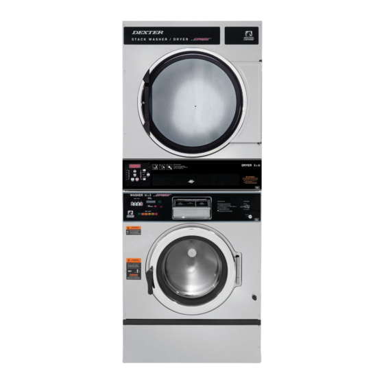
COMMERCIAL STACK WASHERS
MODELS T-350SWD, T-450SWD AND T-750SWD
VENDED C-SERIES CONTROL
WARNING - THIS WASHER IS EQUIPPED WITH DEVICES AND FEATURES RELATING TO ITS SAFE
OPERATION. TO AVOID INJURY OR ELECTRICAL SHOCK, DO NOT PERFORM ANY SERVICING UNLESS
QUALIFIED TO DO SO.
IT IS THE RESPONSIBILITY OF THE OWNER TO CHECK THIS EQUIPMENT ON A FREQUENT
BASIS TO ASSURE ITS SAFE OPERATION.
A machine should NOT be allowed to operate if any of the following occur:
-
Excessively high water level.
-
If machine is not connected to a properly grounded circuit.
-
If the door does not remain securely locked during the entire cycle.
-
Vibration or shaking from an inadequate mounting or foundation.
WARNING - SAFETY PRECAUTIONS
-
Always shut off power and water supply before servicing.
Do not overload the washer.
-
Do not open door when cylinder is in motion or it contains water.
-
Do not bypass any safety devices of this washer.
-
Do not use volatile or flammable substances in or near this washer.
-
-
Keep all panels in place. They protect against shock and injury and add rigidity to the washer.
PREVENTIVE MAINTENANCE REQUIREMENTS
DAILY
Check that the loading door remains securely locked and cannot be opened during an entire
-
cycle.
Check the water connections for leaks.
-
Clean the top, front, and sides of the cabinet to remove residue.
-
Clean the soap dispenser and lid and check that all dispenser mounting screws are in-place and
-
tight.
-
Check the drain valve for leaking and that it opens properly.
-
Check the loading door for leaks. Clean the door seal of all foreign matter.
Leave the loading door open to aerate the washer when not in use.
-
QUARTERLY
Make sure the washer is inoperative by switching off the main power supply.
-
-
Check the V-belts for wear and proper tension.
Clean lint and other foreign matter from around motor.
-
Check all water connections for leaks.
-
Wipe and clean the inside of the washer and check that all electrical components are free of
-
moisture and dust.
-
Remove and clean water inlet hose filters. Replace if necessary.
-
Check anchor bolts. Retighten if necessary
IMPORTANT: Replace any and all panels that were removed to perform daily and/or quarterly
maintenance.
8514-298-001 REV A page 1
OPERATOR'S MANUAL
INSTALLATION & OPERATION
INSTRUCTIONS
Please read this information and retain for reference.
Advertisement
Table of Contents

Related Manuals for Dexter Laundry T-450SWD


Summary of Contents for Dexter Laundry T-450SWD
- Page 1 COMMERCIAL STACK WASHERS MODELS T-350SWD, T-450SWD AND T-750SWD VENDED C-SERIES CONTROL OPERATOR’S MANUAL INSTALLATION & OPERATION INSTRUCTIONS Please read this information and retain for reference. WARNING - THIS WASHER IS EQUIPPED WITH DEVICES AND FEATURES RELATING TO ITS SAFE OPERATION. TO AVOID INJURY OR ELECTRICAL SHOCK, DO NOT PERFORM ANY SERVICING UNLESS QUALIFIED TO DO SO.
-
Page 2: Table Of Contents
TABLE OF CONTENTS SPECIFICATION SHEET ..................3 INSTALLATION INSTRUCTIONS ................4 FOUNDATION REQUIREMENTS ..............4 MOUNTING ....................4 2.2.1 T-350 SWD Machine Mounting Detail ............6 2.2.2 T-350 SWD Commercial Washer Dimensions ..........7 2.2.3 T-450 SWD Machine Mounting Detail ............8 2.2.4 T-450 SWD Commercial Washer Dimensions .......... -
Page 3: Specification Sheet
SPECIFICATION SHEET T-350 STACK WASHER-DRYER UNIT T-450 STACK WASHER-DRYER UNIT T-750 STACK WASHER-DRYER UNIT Capacity Dry Weight Capacity Per Machine - lb (kg) (9.1) (13.6) (22.7) Washer Cylinder Volume - cu ft (L) (76.5) (113.3) (184.1) Dryer Cylinder Volume - cu ft (L) (198.2) 11.3 (320) -
Page 4: Installation Instructions
T-750 SWD: approximately 4 inches (102 mm) Allow a minimum 24 inches (610 mm) of clearance behind the rear of the machine to provide access for motor service. Contact a Dexter laundry equipment distributor for recommended steel mounting bases. If an elevated concrete pedestal is desired, it should be embedded and tied into the existing floor (cut through existing floor as shown). - Page 5 Machine Mounting Detail Figures for floor thickness and bolt sizes. EXPANSION ANCHORS ARE NOT RECOMMENDED FOR USE IN CONCRETE PEDESTALS BECAUSE THE ANCHORS ARE TOO CLOSE TO AN EDGE, CAUSING IT TO BREAK OUT. 8514-298-001 REV A page 5...
-
Page 6: T-350 Swd Machine Mounting Detail
2.2.1 T-350 SWD Machine Mounting Detail 8514-298-001 REV A page 6... -
Page 7: T-350 Swd Commercial Washer Dimensions
2.2.2 T-350 SWD Commercial Washer Dimensions 8514-298-001 REV A page 7... -
Page 8: T-450 Swd Machine Mounting Detail
2.2.3 T-450 SWD Machine Mounting Detail 8514-298-001 REV A page 8... -
Page 9: T-450 Swd Commercial Washer Dimensions
2.2.4 T-450 SWD Commercial Washer Dimensions 8514-298-001 REV A page 9... -
Page 10: T-750 Swd Machine Mounting Detail
CONCRETE PEDESTAL MOUNTING FLOOR OUTLINE Figure 1-1 Figure 1-2 2.2.5 T-750 SWD Machine Mounting Detail 8514-298-001 REV A page 10... -
Page 11: T-750 Swd Commercial Washer Dimensions
2.2.6 T-750 SWD Commercial Washer Dimensions 8514-298-001 REV A page 11... -
Page 12: Plumbing
PLUMBING Water supply hoses are provided with each machine. The threaded connections on the hoses are ¾-11 ½ NHT for 60 Hz models and ¾-14 BSP for 50 Hz models. Separate hot and cold water lines must be supplied to the machine, maintaining 30 psi to 120 psi (207 kPa to 827 kPa) water flow pressure. - Page 13 WARNING: SHUT OFF POWER AND WATER BEFORE OPENING ANY SERVICE PANELS. ELECTRICAL CONNECTIONS 8514-298-001 REV A page 13...
-
Page 14: Installing The Electrical Connection
NOT be connected to L1 or L2. However, failure due to a voltage surge on the high leg is not covered by equipment warranty. Contact Dexter Laundry with any questions. 2.6.1.4 If power is 208-240V-1PH-60Hz, connect L1, L2 and Ground. -
Page 15: Controls Transformer
2.6.3 CONTROLS TRANSFORMER The controls transformer is located inside the control trough and steps a range of 180 to 255 volts down to 24 volts. There are two terminals on the controls transformer for the primary (incoming) power. Use the terminal marked “L1 200V” for power supplies between 180 and 229 volts. -
Page 16: Operating Instructions
OPERATING INSTRUCTIONS STARTING THE WASHER 3.1.1 Turn on power to the washer. 3.1.2 Load the laundry. Place laundry into the cylinder and latch the door securely. Be sure laundry does not get caught between the door gasket and tub front when closing the door. -
Page 17: End Of Cycle
END OF CYCLE When the cycle is complete a 3-second tone will sound and the display will read “CYCLE DONE THANK YOU” until the door is opened. The door can now be opened. Leave the clothes door open when the machine is not in use. - Page 18 “READY” “FAULT” “RUN” Washer Condition LED Status Status Status Idle Mode (No Cylinder Movement) Tumbling Stop from Tumble FLASHING Ramp to Intermediate or Final Extract Spin Spinning (Intermediate or Final) Stop from Spin FLASHING (Intermediate or Final) Faulted Table 1: Variable Frequency Drive Indicators 8514-298-001 REV A page 18...
-
Page 19: Machine Programming Instructions
MACHINE PROGRAMMING INSTRUCTIONS The washer control can be programmed to prompt the user for alternate vend prices, change washer cycle times, temperatures and many other options. This can be accomplished in two ways: 1. Manual programming utilizing the “Start”, “Hot”, “Warm” and “Cold” buttons 2. - Page 20 When manual programming mode is entered, the “Start”, “Hot”, “Warm” and “Cold” buttons perform alternate functions. Button Name Alternate Function in Programming Mode Becomes the action to accept the displayed option or Start the “Enter” key Becomes the action to move UP through displayed options (Press &...
- Page 21 8514-298-001 REV A page 21...
-
Page 22: Optional Cycles Option
Optional Cycles Option: This option allows the user to select the different test and short-cycle options. 1. “Quick Test” will begin a shortened wash cycle without the displayed vend price being met. The purpose of this shortened cycle is to test all major components for proper operation. -
Page 23: Error Code Historical Log
Error Code Historical Log: The last five occurring error codes will be stored in the control with a time and date stamp. The purpose of this option is only to observe the history of these code occurrences (no changes can be made). The time is based off the Real Time Clock, but potentially shifted by the user’s manual programming changes (Shift Hours option) and/or network time override. -
Page 24: Temp Pricing Option
Temp Pricing Option: The Temperature Pricing option allows for the user to prompt the customer for varying vend prices based on the water temperature the customer selects. If a value other then 0 is programmed for either the “WARM ADDER” or “HOT ADDER”, the feature becomes active. - Page 25 The “Final Spin” can be adjusted in increments of 10 G for washers with a 100G maximum spin speed and increments of 20 G for washers with a 200G maximum spin speed. The factory default “Final spin” speeds are the maximum values. Model Adjustable Final Spin Range...
- Page 26 The figure below shows the sub menu options for Cycles: 8514-298-001 REV A page 26...
-
Page 27: Plus Cycle Options
Plus Cycle Options: The “Plus Cycle” options allow for the user to prompt the customer for varying vend prices based on additional wash baths chosen. In general, the user can program the additional wash baths in a similar manner to what was described in the “Cycles” Options section. - Page 28 programmed, the customer will be prompted to add additional coins if they wish to purchase the “Extra Rinse” feature. This prompt will occur during the standard “Final Rinse” bath. If the customer does not meet the vend price of the “Extra Rinse”...
- Page 29 The figure below shows the sub menu options for Plus Cycle Options: 8514-298-001 REV A page 29...
-
Page 30: Settings
Settings: The “Settings” options allow for the user to make various programming changes to change how the control operation affects the customer. See below for detailed information on each next level option. 1. “Decimal Point”- If the user programs the Decimal Point to “OFF”, control display will not show a decimal point on any vend price values. - Page 31 press the “Enter” button to move to the minutes. Once the hours and minute are both chosen, the “Enter” button must be held down for 3 seconds to confirm that RTC is meant to be reset to the complete entry. 7.
- Page 32 The figure below shows the sub menu options for Settings: 8514-298-001 REV A page 32...
-
Page 33: Usage Menu
Usage Menu: The Usage menu allows for the user to track data about machine usage. See below for detailed information on each sub menu option. 1. “Coin Audit”: The coin audit field shows the accumulation of coin pulses that were sent to the control over each of the left and right coin inputs. Note that this is a count of coin pulses, not an accumulated report of vend value. - Page 34 The figure below shows the sub menu options for Usage: 8514-298-001 REV A page 34...
-
Page 35: Control Menu
4.10 Control Menu: The Control menu allows for the user to observe important technical information for the control. No changes can be made at this menu. See below for detailed information on each sub menu. 1. “Serial Number”: This is the control serial number. 2. -
Page 36: Coin Washer Default Cycle
4.11 COIN WASHER DEFAULT CYCLE The following table shows the complete details for the coin washer default cycle. Bath Bath Cycle Water Delay Fill Spin Time Time (min.) Temp. (min.) Prewash Cold Wash Warm Extend Wash Rinse Cold Final Rinse Cold Extra Rinse Spin Extra Rinse Bath... -
Page 37: Water Level Adjustment
4.14 WATER LEVEL ADJUSTMENT The water level of all baths can be adjusted by changing the switch settings on the electronic pressure sensor. Vended washers are shipped with the pressure sensor harness connected to Switch #1 and factory set for an energy-efficient water level. Switch #2 is factory set for the classic water level. -
Page 38: Displayed Washer Messages
DISPLAYED WASHER MESSAGES Displayed Fault Code Description DOOR This error is when the Door Locked signal is not Door Lock LOCK Condition received within one second after the start of the cycle. Error fter three attempts to start the washer. ERROR Delay Immediate... - Page 39 Check VFD fault light before turning off power. Try the data cable first. Move around cable and remove any side loading tension from data cable connector ends. Solution Check connection P23 to P15. Turn power back on to the washer. If the problem returns, replace the PCB washer controller.
- Page 40 Check the data communication cable between the washer computer and the variable frequency drive (VFD). Step 1: Make sure the cable did not become unplugged during operation. Step 2: Make sure that the cable is not being pulled sideways at either the washer controller, or the VFD, Solution plug end.
- Page 41 Check VFD fault light before turning off power. Inspect the braking resistors and measure the resistance. Check connecting wiring from braking resistor to the Solution drive mounted in the top of the washer. Reset the drive and try again. Possibly incorrectly programmed drive.
- Page 42 This error is when the drive size does not match the Condition washer size. Immediate. (after the size jumper configuration is Washer size/ DRIVE read). Washer size/type inputs are read only at power VFD size Delay ERROR1 up, before starting a cycle, once every 24 hours and in mismatch factory test mode Stop the machine and clear the cycle.
- Page 43 VFD Over- DRIVE OV Condition This error is over-voltage on the VF drive voltage Fault Delay Delay time is 35 seconds. Stop the machine and clear the cycle. Keep the door Action locked until the machine has stopped moving and then unlock the door.
- Page 44 VFD Ground DRIVE GFI Condition This error is a ground fault interruption on the VF drive Fault Delay Delay time is 12 seconds. Stop the machine and clear the cycle. Keep the door Action locked until the machine has stopped moving and then unlock the door.
- Page 45 COMM Condition This error indicates that a VFD exception error is set and ERROR6 Communication there is no VFD fault in the VFD fault register and there is Fault no COMM ERROR 5 condition. Delay Occurs following the “DELAY” error (see corresponding detail) Action Stop the machine and clear the cycle.
-
Page 46: Troubleshooting
TROUBLESHOOTING CAUTION: Label all wires prior to disconnection when servicing controls. Wiring errors can cause improper and dangerous operation. Verify proper operation after servicing. ATTENTION: Lors des opérations d'entretien des commandes, étiqueter tous les fils avant de les déconnecter. Toute erreur de câblage peut être une source de danger et de panne. If any of the following symptoms occur on this washer, check the suggested remedies listed below. - Page 47 Check for continuity through door latch switch when Door Switch door closed. If no continuity, adjust or replace door switch. Check to see if thermoactuator and its mechanism are stuck or binding and not allowing the door lock motor to open. Check to be sure that the locking thermoactuator is not receiving 24 VAC during the last Door will not 1 1/2 minutes of the cycle.
- Page 48 Check these areas: • Drain valve blockage. • Drain valve motor and gear train. If there is power Water comes to the valve but drain valve does not close, replace in but level Drain Valve (open) drain valve and motor. does not rise •...
- Page 49 Machine does Main PCB controls time of the cycle and the end of Main PCB not stop cycle. Check braking resistors for continuity. Verify ohms Braking Resistors resistance at braking resistors with wires removed. Door may need adjustment due to abuse or wear. Check tightness around perimeter using a dollar bill.
-
Page 50: Transient Voltage Surge Suppressors
TRANSIENT VOLTAGE SURGE SUPPRESSORS IMPORTANT Like most electrical equipment your new machine can be damaged or have its life shortened by voltage surges due to lightning strikes which are not covered by factory warranty. Local power distribution problems also can be detrimental to the life of electrical components. -
Page 51: Service And Parts
9565-003-001 (All) Strainer, Inlet Hose Contact distributor or Dexter Laundry, Inc. if a steel-mounting base is required. For service and parts information, contact your local Dexter agent. To find your local Dexter agent, use the Distributor Locator at the website shown below. If a Dexter agent is not available, contact Dexter Laundry, Inc.
Need help?
Do you have a question about the T-450SWD and is the answer not in the manual?
Questions and answers