Brocade Communications Systems 5100 Hardware Reference Manual
Hide thumbs
Also See for 5100:
- Quick start manual (2 pages) ,
- Reference manual (370 pages) ,
- Administrator's manual (96 pages)
Table of Contents
Advertisement
Advertisement
Table of Contents

Related Manuals for Brocade Communications Systems 5100


Summary of Contents for Brocade Communications Systems 5100
- Page 1 53-1000854-06 03 March 2014 Brocade 5100 Hardware Reference Manual...
- Page 2 Notice: This document is for informational purposes only and does not set forth any warranty, expressed or implied, concerning any equipment, equipment feature, or service offered or to be offered by Brocade. Brocade reserves the right to make changes to this document at any time, without notice, and assumes no responsibility for its use.
-
Page 3: Table Of Contents
Brocade 5100 Introduction ...................... 9 Brocade 5100 overview..................9 Port side of the Brocade 5100.................10 Port Numbering................... 11 Non-port side of the Brocade 5100..............11 Field replaceable units (FRUs)................11 Ports on Demand license................12 ISL trunking groups..................12 Brocade 5100 Installation and Configuration................13 Items included with the Brocade 5100............ - Page 4 Boot....................25 Interpreting POST results................25 Maintaining the Brocade 5100..............26 Installing an SFP................26 Diagnostic tests.................26 Field Replaceable Units (FRUs)............27 Power supply/fan assembly FRU replacement......... 27 Managing the Brocade 5100.................28 Brocade 5100 Specifications....................31 Switch components..................31 Weight and physical dimensions..............31 Facility requirements..................32 Power supply specifications................32...
-
Page 5: Preface
Document conventions The document conventions describe text formatting conventions, command syntax conventions, and important notice formats used in Brocade technical documentation. Text formatting conventions Text formatting conventions such as boldface, italic, or Courier font may be used in the flow of the text to highlight specific words or phrases. -
Page 6: Notes, Cautions, And Warnings
DANGER A Danger statement indicates conditions or situations that can be potentially lethal or extremely hazardous to you. Safety labels are also attached directly to products to warn of these conditions or situations. Brocade 5100 Hardware Reference Manual 53-1000854-06... -
Page 7: Brocade Resources
Select your platform and scroll down to the Documentation section. • For all other products, select the Brocade Products tab to locate your product, then click the Brocade product name or image to open the individual product page. The user manuals are available in the resources module at the bottom of the page under the Documentation category. -
Page 8: Document Feedback
Quality is our first concern at Brocade and we have made every effort to ensure the accuracy and completeness of this document. However, if you find an error or an omission, or you think that a topic needs further development, we want to hear from you. -
Page 9: About This Document
Communications Systems, Inc. for Fabric OS v6.1.0, documenting all possible configurations and scenarios is beyond the scope of this document. This document is specific to the Brocade 5100 and Fabric OS v6.1.0. To obtain information about a Fabric OS version other than v6.1.0, see the documentation specific to that OS version. - Page 10 What’s new in this document Brocade 5100 Hardware Reference Manual 53-1000854-06...
-
Page 11: Brocade 5100 Introduction
Because the Brocade 5100 has a slim 1U height and a high port count, you can use the Brocade 5100 to create very dense fabrics in a relatively small space. With its flexible Ports On Demand (POD) capability, the Brocade 5100 provides excellent overall value as the foundation of a SAN with the ability to grow with an organization’s SAN needs. -
Page 12: Port Side Of The Brocade 5100
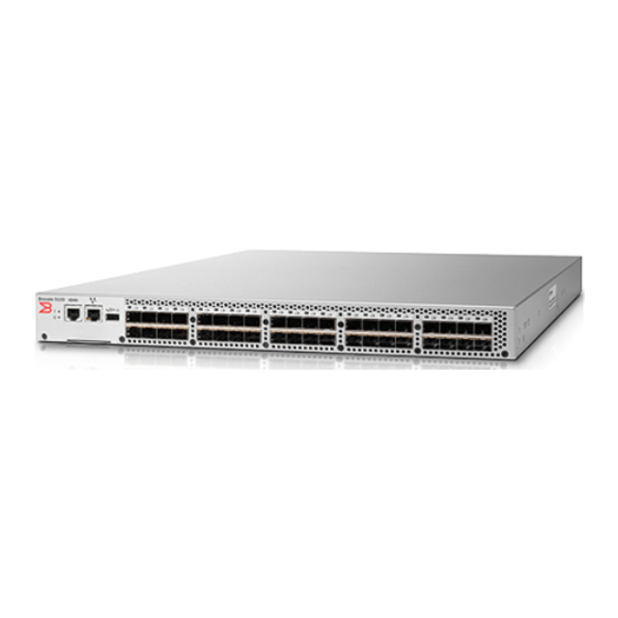
Port side of the Brocade 5100 The port side of the Brocade 5100 includes the system status LED, console port, Ethernet port and LEDs, USB port, and Fibre Channel ports and the corresponding port status LEDs. FIGURE 1 Port-side view of the Brocade 5100... -
Page 13: Port Numbering
Port Numbering Port Numbering The Fibre Channel ports on the Brocade 5100 are numbered from left to right, in eight-port groups from 0 to 39 as illustrated in the following figure. FIGURE 2 Port Numbering on the Brocade 5100 ATTENTION Brocade ISL Trunking is licensed software that allows you to create trunking groups of ISLs between adjacent switches. -
Page 14: Ports On Demand License
FRUs. Ports on Demand license The Brocade 5100 has 40 ports. By default, ports 0-24 are enabled. To enable additional ports, you must install Ports On Demand (POD) licenses. To install a POD license, you can either use the supplied license key or generate a license key. -
Page 15: Brocade 5100 Installation And Configuration
Items included with the Brocade 5100 The following items are included with the standard shipment of the Brocade 5100. When you open the Brocade 5100 packaging, verify that these items are included in the package and that no damage has occurred during shipping: •... -
Page 16: Environmental Considerations
You should not use tie wraps with optical cables because they are easy to over tighten. CAUTION Before plugging a cable to any port, be sure to discharge any static charge stored on the cable by touching the electrical contacts to ground surface. Brocade 5100 Hardware Reference Manual 53-1000854-06... -
Page 17: Items Required For Installation
• Use hook and loop style straps to secure and organize fiber optic cables. Items required for installation The following items are required for installing, configuring, and connecting the Brocade 5100 for use in a network and fabric: • Workstation with an installed terminal emulator, such as HyperTerminal •... -
Page 18: Cabinet Installation For A Brocade 5100
Brocade 5100 configuration Once you have set up the Brocade 5100 in a rack or as a standalone switch, it is time to give it power and a basic configuration. If you are going to use the Brocade 5100 in a single-switch setup, you can use EZSwitchSetup to complete the basic configuration. -
Page 19: Switch Ip Address
DHCP server. The DHCP client can only connect to a DHCP server that is on the same subnet as the switch. If your DHCP server is not on the same subnet as the Brocade 5100, use a static IP address. -
Page 20: Date And Time Settings
Date and time are used for logging events. Switch operation does not depend on the date and time; a Brocade 5100 with an incorrect date and time value still functions properly. However, because the date and time are used for logging, error detection, and troubleshooting, you should set them correctly. - Page 21 You must perform the procedure on all switches for which the time zone must be set. However, you only need to set the time zone once on each switch, because the value is written to nonvolatile memory. Use one of the two following procedures to set the time zone. Brocade 5100 Hardware Reference Manual 53-1000854-06...
- Page 22 The following example shows how to set up more than one NTP server using a DNS name: switch:admin> tsclockserver "10.32.170.1;10.32.170.2;ntp.localdomain.net" Updating Clock Server configuration...done. Updated with the NTP servers Changes to the clock server value on the principal or primary FCS switch are propagated to all switches in the fabric Brocade 5100 Hardware Reference Manual 53-1000854-06...
-
Page 23: Brocade 5100 Operation
Powering the Brocade 5100 on and off To power the Brocade 5100 on, connect one or both power cords to the power connectors on the power supplies and to a power source; then, set the AC power switches to "I". Power is supplied to the switch as soon as the first power supply is connected and powered on. -
Page 24: Led Locations
LED locations LED locations FIGURE 4 Port Side LEDs on the Brocade 5100. System status LED (top) and System power (bottom) Ethernet port Status LEDs (green/amber) FC port status (port 9) FIGURE 5 Non-Port Side LEDs on the Brocade 5100. - Page 25 Brocade 5100 Operation TABLE 1 Brocade 5100 LED Patterns During Normal Operation LED Name LED Color Status of Hardware Recommended Action Power Supply No light Primary power cord is disconnected or Verify the power supply is on and Status is not actively powered, or power seated and the power cord is supply has failed.
-
Page 26: Post And Boot Specifications
POST and boot specifications TABLE 1 Brocade 5100 LED Patterns During Normal Operation (Continued) LED Name LED Color Status of Hardware Recommended Action Steady amber There is a link. No action required. Flickering amber There is link activity (traffic). No action required. -
Page 27: Boot
For information about all referenced commands, and on accessing the error log, refer to Fabric OS Administrator’s Guide . For information about error messages, refer to the Fabric OS Message Reference Manual . Brocade 5100 Hardware Reference Manual 53-1000854-06... -
Page 28: Maintaining The Brocade 5100
Maintaining the Brocade 5100 Maintaining the Brocade 5100 The Brocade 5100 does not require any regular physical maintenance and is designed for high availability and to minimize the chance of failure. It includes diagnostic tests and field-replaceable units, described in the following sections. -
Page 29: Field Replaceable Units (Frus)
Power supply/fan assembly FRU replacement The Brocade 5100 fans are fixed inside the integrated power supply/fan FRU to provide necessary airflow to cool the whole system. There is one fan located in the rear section of each FRU. The system software sets fan speed and measures their speeds through the tachometer interface. -
Page 30: Managing The Brocade 5100
Fan Assembly Replacement Procedure . Managing the Brocade 5100 You can use the management functions built into the Brocade 5100 to monitor the fabric topology, port status, physical status, and other information to help you analyze switch performance and to accelerate system debugging. - Page 31 Brocade 5100 Operation TABLE 2 Management Options for the Brocade 5100 Switch (Continued) Management Tool Out-of-band Support In-band Support Management Server Ethernet or serial Native in-band interface(over connection HBA only) For information, refer to the Fabric OS Administrator’s Guide and the Fabric OS Command Reference Manual .
- Page 32 Managing the Brocade 5100 Brocade 5100 Hardware Reference Manual 53-1000854-06...
-
Page 33: Brocade 5100 Specifications
One USB port for system log file downloads or firmware upgrades • Two universal AC input and redundant power supplies with AC switches and built-in fans Weight and physical dimensions The following table lists the weight and dimensions of the Brocade 5100. TABLE 3 Physical Specifications Dimension... -
Page 34: Facility Requirements
428.75 mm (16.88 inches) Weight (with two power supply/fan assembly units installed, no SFPs) 9.3 kg (20.6 lbs) Facility requirements The following table provides the facilities requirements that must be met for the Brocade 5100. TABLE 4 Facility Requirements Type... -
Page 35: Environmental Requirements
2.0 G sine, 1.1 grms random 5-500 Hz Air flow High speed, 13,000 RPM, 49.3 CMH (29 CFM) None required Low speed, 7000 RPM, 37.4 CMH (22 CFM) General specifications The following table lists the general specifications for the Brocade 5100. Brocade 5100 Hardware Reference Manual 53-1000854-06... - Page 36 Complies with FC-IP 2.3 of FCA profile Aggregate switch I/O bandwidth 640 Gbps if all 40 ports are running at 8 Gbps, full duplex Port-to-port latency 700 nanoseconds The following table lists the EMC (electromagnetic compatibility) for the Brocade 5100. TABLE 8 EMC specifications Country Safety...
-
Page 37: Data Transmission Ranges
62.5 70 m (230 feet) 8 Gbps 50 m (164 ft) (OM2)150 m (492 ft) (OM3) 62.5 21 m (69 feet) 10 km Memory specifications The Brocade 5100 has three types of memory devices. Brocade 5100 Hardware Reference Manual 53-1000854-06... -
Page 38: Fibre Channel Port Specifications
The ports are capable of operating at 1, 2, 4, or 8 Gbps and are able to autonegotiate to the higher speed. Serial port specifications The serial port is located on the port side of the switch. The Brocade 5100 uses an RJ-45 connector for the serial port. NOTE To protect the serial port from damage, keep the cover on the port when not in use. -
Page 39: Regulatory Compliance
Logic ground UART1_RXD Receive data Not supported Not supported Regulatory compliance This section describes the regulatory compliance requirements for the Brocade 5100 switch. It contains: • FCC warning (US only) on page 37 next • KCC statement (Republic of Korea) on page 37 •... -
Page 40: China Statement
Class A device (Broadcasting Communication Device for Office Use): This device obtained EMC registration for office use (Class A), and may be used in places other than home. Sellers and/or users need to take note of this. China statement Brocade 5100 Hardware Reference Manual 53-1000854-06... -
Page 41: Vcci Statement Japan
This is a Class A product. In a domestic environment, this product might cause radio interference, and the user might be required to take corrective measures. The standards compliance label on the Brocade 5100 contains the CE mark which indicates that this system conforms to the provisions of the following European Council directives, laws, and standards: •... -
Page 42: Canadian Requirements
Standards, 21 CFR Subchapter I and the international laser safety standard IEC 825-2. ATTENTION Use only optical transceivers that are qualified by Brocade Communications Systems, Inc. and comply with the FDA Class 1 radiation performance requirements defined in 21 CFR Subchapter I, and with IEC 825-2. -
Page 43: Regulatory Certifications
In no event do the EPUP logos shown on the product and FRUs alter or expand that warranty that Brocade provides with respect to its products as set forth in the applicable contract between Brocade Brocade 5100 Hardware Reference Manual... - Page 44 TS/HS dual language sheet and its customer. Brocade hereby disclaims all other warranties and representations with respect to the information contained on this CD including the implied warranties of merchantability, fitness for a particular purposes and non-infringement. The EPUP assumes that the product will be used under normal conditions in accordance with the operating manual of the product.
- Page 45 X indicates that the concentration of such hazardous/toxic substance in all the units of homogeneous material of such component is higher than the SJ/T11363-2006 Requirements for Concentration Limits. O indicates that no such substances are used or that the concentration is within the aforementioned limits. Brocade 5100 Hardware Reference Manual 53-1000854-06...
- Page 46 Brocade 5100 Specifications Brocade 5100 Hardware Reference Manual 53-1000854-06...
-
Page 47: Index
Brocade Fabric Manager LEDs Brocade ISL Trunking 11, BSMI statement (Chinese) BSMI statement (Taiwan) installing a Brocade 5100 into an EIA cabinet installing an SFP installing a stand-alone Brocade 5100 Canadian requirements interpreting POST results CE statement IP over Fibre Channel (FC-IP) - Page 48 19, requirements tsTimeZone recommendations for cable management regulatory certifications regulatory compliance requirements airflow VCCI statement electrical environmental 32, facility rack weight, switch shock and vibration temperature and humidity RJ-45 connector RS-232 connector RTC battery Brocade 5100 Hardware Reference Manual 53-1000854-06...
Need help?
Do you have a question about the 5100 and is the answer not in the manual?
Questions and answers