Table of Contents
Advertisement
Advertisement
Table of Contents

Subscribe to Our Youtube Channel
Related Manuals for Brocade Communications Systems DS-5100B - Connectrix Switch - 8Gb Fibre Channel


Summary of Contents for Brocade Communications Systems DS-5100B - Connectrix Switch - 8Gb Fibre Channel
- Page 1 53-1000854-02 July 18, 2008 Brocade 5100 Hardware Reference Manual...
- Page 2 Copyright © 2008 Brocade Communications Systems, Inc. All Rights Reserved. Brocade, Fabric OS, File Lifecycle Manager, MyView, and StorageX are registered trademarks and the Brocade B-wing symbol, DCX, and SAN Health are trademarks of Brocade Communications Systems, Inc., in the United States and/or in other countries. All other brands, products, or service names are or may be trademarks or service marks of, and are used to identify, products or services of their respective owners.
-
Page 3: Table Of Contents
Contents About This Document In this chapter ......... . . vii How this document is organized . - Page 4 Brocade 5100 configuration ....... 10 Providing power to the switch ......10 Creating a serial connection .
- Page 5 Regulatory compliance ........32 FCC warning (US only) ....... . . 33 MIC statement (Republic of Korea) .
- Page 6 Brocade 5100 Hardware Reference Manual 53-1000854-02...
-
Page 7: About This Document
About This Document In this chapter • How this document is organized ........vii •... -
Page 8: What's New In This Document
What’s new in this document Corrections have been made to the original document. Document conventions This section describes text formatting conventions and important notice formats used in this document. Text formatting The narrative-text formatting conventions that are used are as follows: bold text Identifies command names Identifies the names of user-manipulated GUI elements... -
Page 9: Notice To The Reader
Notes, cautions, and warnings The following notices and statements are used in this manual. They are listed below in order of increasing severity of potential hazards. NOTE A note provides a tip, guidance or advice, emphasizes important information, or provides a reference to related information. -
Page 10: Brocade Resources
Brocade resources To get up-to-the-minute information, join Brocade Connect. It’s free! Go to http://www.brocade.com and click Brocade Connect to register at no cost for a user ID and password. For practical discussions about SAN design, implementation, and maintenance, you can obtain Building SANs with Brocade Fabric Switches through: http://www.amazon.com For additional Brocade documentation, visit the Brocade SAN Info Center and click the Resource... -
Page 11: Document Feedback
2. Switch Serial Number The switch serial number and corresponding bar code are provided on the serial number label, as illustrated below.: *FT00X0054E9* FT00X0054E9 The serial number label is located as follows: • Brocade 200E—On the non-port side of the chassis •... - Page 12 Brocade 5100 Hardware Reference Manual 53-1000854-02...
-
Page 13: In This Chapter
Chapter Brocade 5100 Introduction In this chapter • Brocade 5100 overview ......... . 1 •... -
Page 14: Port Side Of The Brocade 5100
Port side of the Brocade 5100 • Inter-Switch Link (ISL) Trunking (licensable), which allows up to eight ports (at 1, 2, 4, or 8 Gbps speeds) between a pair of switches combined to form a single, logical ISL with a speed of up to 128 Gbps full duplex for optimal bandwidth utilization and load balancing. -
Page 15: Port Numbering
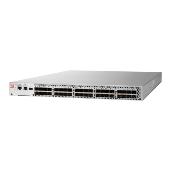
Port side of the Brocade 5100 System status (top) and power (bottom) LEDs System RS232 console port (RJ-45) System Ethernet port (RJ-45) Ethernet port LEDs (green/amber) USB port Fibre Channel port status LED Fibre Channel ports Switch ID pull-out tab FIGURE 1 Port-side view of the Brocade 5100 Port Numbering... -
Page 16: Non-Port Side Of The Brocade 5100
Non-port side of the Brocade 5100 ATTENTION Brocade ISL Trunking is licensed software that allows you to create trunking groups of ISLs between adjacent switches. For more information about Brocade ISL Trunking, refer to the Brocade Fabric OS Administrator’s Guide. Non-port side of the Brocade 5100 The non-port side of the Brocade 5100 includes the two redundant power supply-fan assemblies and the corresponding status LEDs. -
Page 17: Ports On Demand License
Ports on Demand license Ports on Demand license The Brocade 5100 has 40 ports. By default, ports 0-24 are enabled. To enable additional ports, you must install Ports On Demand (POD) licenses. To install a POD license, you can either use the supplied license key or generate a license key. Typically the switch is shipped with a paper pack that specifies the transaction key to use with the Software License Keys link. - Page 18 ISL trunking groups Brocade 5100 Hardware Reference Manual 53-1000854-02...
-
Page 19: Chapter 2 Brocade 5100 Installation And Configuration
Chapter Brocade 5100 Installation and Configuration In this chapter • Items included with the Brocade 5100 ......7 •... -
Page 20: Electrical Considerations
Installation and safety considerations Electrical considerations To install and operate the switch successfully, ensure the following: • The primary outlet is correctly wired, protected by a circuit breaker, and grounded in accordance with local electrical codes. • The supply circuit, line fusing, and wire size are adequate, as specified by the electrical rating on the switch nameplate. -
Page 21: Items Required For Installation
Installing a standalone Brocade 5100 Cables can be organized and managed in a variety of ways, for example, using cable channels on the sides of the cabinet or patch panels to minimize cable management. Following is a list of recommendations: NOTE You should not use tie wraps with optical cables because they are easy to over tighten. -
Page 22: Cabinet Installation For A Brocade 5100
Cabinet installation for a Brocade 5100 ATTENTION Do not connect the switch to the network until the IP address is correctly set. For instructions on how to set the IP address, see “Brocade 5100 configuration” Cabinet installation for a Brocade 5100 You must use one of three rack mount kits to install a Brocade 5100 in a cabinet. -
Page 23: Creating A Serial Connection
Brocade 5100 configuration 3. After POST is complete, verify that the switch power and status LEDs on the left of the port side of the switch are green. Creating a serial connection You will perform all basic configuration tasks in this guide using a serial connection. Complete the following steps to create a serial connection to the switch. -
Page 24: Date And Time Settings
Brocade 5100 configuration 1. Log into the switch using the default password, which is password. 2. Use the ipaddrset command to set the Ethernet IP address. If you are going to use an IPv4 IP address, enter the IP address in dotted decimal notation as prompted. -
Page 25: Setting The Date
Brocade 5100 configuration • System services that have already started will reflect the time zone changes only after the next reboot. • Time zone settings persist across failover for high availability. Local time synchronization You can synchronize the local time of the principal or primary fabric configuration server (FCS) switch to a maximum of eight external network time protocol (NTP) servers. -
Page 26: Setting Time Zones
Brocade 5100 configuration Thu Sep 27 12:30:00 UTC 2007 switch:admin> Setting time zones You must perform the procedure on all switches for which the time zone must be set. However, you only need to set the time zone once on each switch, because the value is written to nonvolatile memory. - Page 27 Brocade 5100 configuration LOCL switch:admin> tsclockserver "132.163.135.131" switch:admin> tsclockserver 132.163.135.131 switch:admin> The following example shows how to set up more than one NTP server using a DNS name: switch:admin> tsclockserver "10.32.170.1;10.32.170.2;ntp.localdomain.net" Updating Clock Server configuration...done. Updated with the NTP servers Changes to the clock server value on the principal or primary FCS switch are propagated to all switches in the fabric Brocade 5100 Hardware Reference Manual...
- Page 28 Brocade 5100 configuration Brocade 5100 Hardware Reference Manual 53-1000854-02...
-
Page 29: In This Chapter
Chapter Brocade 5100 Operation In this chapter • Powering the Brocade 5100 on and off ......17 •... -
Page 30: Led Locations
LED activity interpretation LED locations Figure 4 shows the locations of the port side LEDs on the Brocade 5100. FIGURE 4 Brocade 5100 port side LEDs System status LED (top) and System power (bottom) Ethernet port Status LEDs (green/amber) FC port status (port 9) Figure 5 shows the non-port side LEDs on the Brocade 5100. -
Page 31: Led Patterns
LED activity interpretation LED Patterns Table 1 describes the LEDs and their actions on the switch. TABLE 1 Brocade 5100 LED Patterns During Normal Operation LED Name LED Color Status of Hardware Recommended Action Power Supply No light Primary power cord is disconnected Verify the power supply is on and Status (right) or is not actively powered, or power... -
Page 32: Post And Boot Specifications
POST and boot specifications TABLE 1 Brocade 5100 LED Patterns During Normal Operation (Continued) LED Name LED Color Status of Hardware Recommended Action Port Status No light No signal or light carrier (media or Check transceiver and cable. cable) detected. Slow flashing Port is online but segmented No action required. -
Page 33: Interpreting Post Results
Interpreting POST results 4. Runs diagnostic tests on several functions, including circuitry, port functionality, memory, statistics counters, and serialization. Boot In addition to POST, boot includes the following tasks after POST is complete: 1. Performs universal port configuration. 2. Initializes links. 3. -
Page 34: Installing An Sfp
Maintaining the Brocade 5100 Installing an SFP The Brocade 5100 only supports Brocade-branded SFPs. If you use an unqualified SFP, the switchShow command output shows the port in a Mod_Inv state. Fabric OS also logs the issue in the system error log. Complete the following steps to install an SFP. -
Page 35: Field Replaceable Units (Frus)
Maintaining the Brocade 5100 The tests are implemented by command, either through a Telnet session or through a terminal set up for a serial connection to the switch. Some tests require the ports to be connected by external cables, to allow diagnostics to verify the serializer/deserializer interface, transceiver, and cable. Some tests require loopback plugs. -
Page 36: Managing The Brocade 5100
Managing the Brocade 5100 2. Use one of the following methods to determine whether a fan requires replacement: • Check the system status LED (see Figure 4 on page 18 for location of system status LED). If the system status LED is flashing amber and green, it could mean the fan has failed. The green power supply/fan LED will also flash in the event of failure. - Page 37 Managing the Brocade 5100 NOTE To achieve in-band support for IP over Fibre Channel, the software must be run on both the HBA and the switch, and it must be supported by both the HBA and HBA driver. Brocade 5100 Hardware Reference Manual 53-1000854-02...
- Page 38 Managing the Brocade 5100 Brocade 5100 Hardware Reference Manual 53-1000854-02...
-
Page 39: In This Appendix
Appendix Brocade 5100 Specifications In this appendix • Switch components ..........27 •... -
Page 40: Weight And Physical Dimensions
Weight and physical dimensions Weight and physical dimensions Table 3 lists the weight and dimensions of the Brocade 5100. TABLE 3 Physical Specifications Dimension Value Height 1U = 43 mm (1.7 inches) Depth 610.535 mm (24 inches) Width 428.75 mm (16.88 inches) Weight (with two power supply/fan assembly units installed, no SFPs) 9.3 kg (20.6 lbs) Facility requirements... -
Page 41: Environmental Requirements
Environmental requirements TABLE 5 Power Supply Specifications Specification Value System power consumption 84 Watts nominal, 91 Watts Maximum Input voltage 85 - 264 VAC, Universal Input line frequency 47 - 63 Hz BTU rating 406 BTU/hr Inrush current 35 Amps Maximum Environmental requirements Table 6 lists the acceptable environmental ranges for both operating and nonoperating (such as... -
Page 42: Data Transmission Ranges
Aggregate switch I/O bandwidth 640 Gbps if all 40 ports are running at 8 Gbps, full duplex Port-to-port latency 700 nanoseconds Table 8 lists the EMC (electromagnetic compatibility) for the Brocade 5100. TABLE 8 EMC specifications Country Safety United States Bi_Nat UL/CSA 60950-1 1st Ed or ANSI C63.4... -
Page 43: Memory Specifications
Memory specifications TABLE 9 Laser Data Transmission Ranges Port Speed Cable Size Short Wavelength (SWL) Long Wavelength (LWL) Extended Long (microns) Wavelength (ELWL) 2 Gbps 300 m (984 ft) (OM2) 500 m (1,640 ft) (OM3) 62.5 150 m (492 feet) 10 km (6.2 miles) 40 km (24.8 miles) without a Brocade... -
Page 44: Serial Port Specifications
Serial port specifications Serial port specifications The serial port is located on the port side of the switch. The Brocade 5100 uses an RJ-45 connector for the serial port. NOTE To protect the serial port from damage, keep the cover on the port when not in use. The serial port can be used to connect to a workstation to configure the switch IP address before connecting the switch to a fabric or IP network. -
Page 45: Fcc Warning (Us Only)
Regulatory compliance • “Regulatory certifications” on page 35 FCC warning (US only) This equipment has been tested and complies with the limits for a Class A computing device pursuant to Part 15 of the FCC Rules. These limits are designed to provide reasonable protection against harmful interference when the equipment is operated in a commercial environment. -
Page 46: Bsmi Statement (Taiwan)
The standards compliance label on the Brocade 5100 contains the CE mark which indicates that this system conforms to the provisions of the following European Council directives, laws, and standards: • Electromagnetic Compatibility (EMC) Directive 2004/108/EEC • Low Voltage Directive (LVD) 2006/95/EC •... -
Page 47: Laser Compliance
This product is designed for an IT power system with phase-to-phase voltage of 230V. After operation of the protective device, the equipment is still under voltage if it is connected to an IT power system. Regulatory certifications Table 12 lists the EMC compatibility for the Brocade 5100. TABLE 12 EMC (electromagnetic compatibility) Country... -
Page 48: Environmental Regulation Compliance
Environmental regulation compliance TABLE 12 EMC (electromagnetic compatibility) Country Safety Australia/New Zealand EN55022 or CISPR22 or AS/NZS CISPR22 Argentina IEC60950-1 or latest Russian Federation IEC60950-1 or latest 51318.22-99 and 51318.24.99 Korea KN22 and KN24 China (PS only) GB4943-2001 and GB17625.1-2003 or latest... - Page 49 Environmental regulation compliance TS/HS dual language sheet In accordance with China's Management Measures on the Control of Pollution caused by Electronic Information products (Decree No. 39 by the Ministry of Information Industry), the following information is provided regarding the names and concentration level of Hazardous substances (HS) which may be contained in this product.
- Page 50 Environmental regulation compliance Brocade 5100 Hardware Reference Manual 53-1000854-02...
- Page 51 Index EIA rack requirements electrical safety access environmental requirements event accessory kit date and time bandwidth, aggregate Fabric Manager Brocade Advanced Web Tools FCC warning (US only) Brocade Fabric Manager Fibre Channel classes, supported Brocade ISL Trunking Fibre Channel ports BSMI statement (Chinese) specifications Field replaceable units (FRUs)
- Page 52 requirements airflow electrical Management Server environmental MIC statement (Republic of Korea) facility monitoring rack through LED activity shock and vibration temperature and humidity RJ-45 connector RS-232 connector RTC battery access serial port specifications physical dimensions of switch setting port time zone configurable types setting the date and time Ethernet port...
- Page 53 VCCI statement weight, switch Brocade 5100 Hardware Reference Manual 53-1000854-02...
- Page 54 Brocade 5100 Hardware Reference Manual 53-1000854-02...
Need help?
Do you have a question about the DS-5100B - Connectrix Switch - 8Gb Fibre Channel and is the answer not in the manual?
Questions and answers