
Related Manuals for Digital Watchdog Snapit DWC-HV421D


Summary of Contents for Digital Watchdog Snapit DWC-HV421D
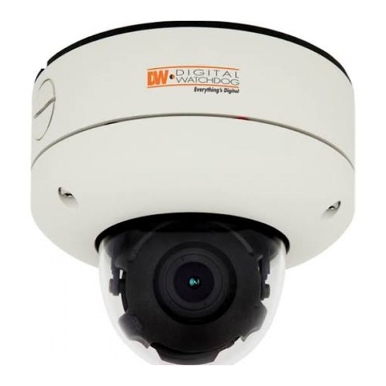
- Page 1 HD-SDI Vandal-Proof Dome Camera DWC-HV421D DWC-HV421TIR ABOUT MANUAL Before installing and using the camera, please read this manual carefully. Be sure to keep it handy for future reference. 08062014...
- Page 2 PRECAUTIONS Do not open or modify. Do not open the case except during maintenence and installation, for it may be dangerous and can cause damages. Do not put objects into the unit. Keep metal objects and flammable substances from entering the camera. It can cause fire, short-circuits, or other damages.
-
Page 3: Table Of Contents
TABLE OF CONTENTS Introduction Features Parts and Descriptions Dimensions Installation Included Accessories Easy Installations 8- 13 Connecting to Monitors Controling the Camera’s OSD Remotely Adjusting the Camera’S Lens Adjusting the 3-Axis Gimbal Camera OSD Menu and Glossary 18-30 Troubleshooting Warranty Information 32-33 Specifications 34-35... - Page 4 FEATURES* Sony 1/2.8” CMOS Sensor Highest Resolution 2.1 Megapixels 720P / 1080P Mode Selectable 3.5~16mm Auto-Focus Lens 4.5X Optical Zoom Double Shutter WDR (Wide Dynamic Range) at 15fps 70ft Range IR with Intelligent Camera Sync [HV421TIR] Electronic Day and Night [HV421D] True Day and Night [HV421TIR] AGC / BLC / AWB 3D DNR (3D Digital Noise Reduction)
- Page 5 PART & DESCRIPTIONS* Lens Power input Connctor 12VDC Voltage BNC (HD-SDI) + RS485 Camera Control Board Bubble Dome Upper Case Flush Mount Case Surface Mount Case Assembly Screws #8 - 32 x 0.75 2nd Video Connector Safety Wire Mounting Screws w/o IR...
-
Page 6: Dimensions
DIMENSIONS IN MILLIMETERS (IN)* Flush Mount 137(5.39”) 101(3.98”) 17(0.67”) 28(1.1”) (4.76”) 98.8(3.89”) 54(2.13”) Surface Mount 139(5.47”) 139(5.47”) 36(1.42”) 118.8 (46.8”) 29(1.41”) (4.76”) 53.8(2.12”) -
Page 7: Inside The Box
INSIDE THE BOX* Included with Snapit Vandal Dome Camera User Manual L-Wrench Mounting Template TORX-T20 Bolt 4 Machine Screw and 4 Dry Wall Anchors Secondary Video-BNC Cable TORX-T20 Wrench... - Page 8 SURFACE MOUNT INSTALLATION INSTRUCTIONS* Use the camera’s mounting Drill holes into the drywall and Pull wires through and make template or your camera to insert the drywall mounts into connections. mark the holes as required. the holes. If you need to keep the wiring within the camera housing, refer to the diagram below.
- Page 9 Snap the camera module onto the base by aligning the red and black markings on the base and the camera module. Secure the three (3) assembly Adjust the camera’s position Tighten the three locking screws. by using the 3-Axis Gimbal. screws in with the L-Wrench to secure the cover dome over the camera.
- Page 10 FLUSH MOUNT INSTALLATION INSTRUCTIONS* For a flush mount housing, detach the surface mount base, which is also known as the junction box, from the flush mount base. Use the mounting template to mark the holes for the screws and a larger hole for the top extruded component of the flush mount base.
- Page 11 WALL MOUNT INSTALLATION INSTRUCTIONS (optional)* Check to see all parts are in Insert the wires from the Use the mounting template to the box. camera through the wall make pilot holes. Use the dry mount housing. wall anchors and woods screws to attach the assembly.
- Page 12 PENDANT MOUNT INSTALLATION INSTRUCTIONS (optional)* Check to see all parts are in Attach the top shield to the Run all necessary cables the box. pendant mount. from the ceiling to the mount. Use the mounting template Connect all cables and verify Attach the camera to the to make pilot holes.
- Page 13 CORNER MOUNT INSTALLATION INSTRUCTIONS (optional)* Check to see all parts are in the box. Attach the two compression fittings to the corner bracket. Attach the wall mount bracket to the corner Mount the camera assembly to the corner of mount using the machine screws. the wall, using wall mount anchors and machine screws.
-
Page 14: Connecting To Monitors
CONNECTING TO MONITORS* Use the diagram below to connect to a Monitor or CRT Monitor properly. DC 12V CCTV Monitor NO IR Second Video Output Monitor 300.0mm(11.8”) Power Connection: 12VDC Voltage. All cameras are equipped with a second video output for on-site configuration. - Page 15 CONTROLLING THE CAMERA’S OSD REMOTELY DWC-HV421D and DWC-HV421TIR, combined with Digital Watchdog’s VMAX HD DVR offer the unique feature of controlling the camera’s OSD menu, focus and zoom all from the DVR with no additional cables other than the BNC cable.
-
Page 16: Adjusting The Camera Lens
ADJUSTING THE CAMERA LENS* Adjusting Auto Focus Lens If pushing the OSD joystick to ‘UP’, the lens will start zoom-in. If pushing the OSD joystick to ‘DOWN’, the lens will start zoom-out. If you keep pushing the joystick, zoom in/out will be continuously operated. When you find the right angle, take off your finger from the joystick and wait. -
Page 17: Adjusting The 3-Axis Gimbal
ADJUSTING THE 3-AXIS GIMBAL* The Gimbal mechanism yields maximum rotation and placement as show below. NO IR NO IR Rotation 360 Panning 360 NO IR Tilting 90 Tilting 75... -
Page 18: Module Osd Menu
MODULE OSD MENU* PROPERTY EXPOSURE LENS BRIGHTNESS LENS TYPE CAMERA ID 0~20 MANUAL, DC, AF 0~255 SHUTTER MODE TITLE AUTO, MANUAL (1/30~1/60000) OUTDOOR,INDOOR/FLK,Deblur120,Deblur240 OPTIC ZOOM TELE, WIDE DISPLAY FOCUS MODE MANUAL, AUTO OFF, x2, x3, x4 NON, ID,, TITLE FOCUSING FAR, NEAR PROTOCOL TIMER... - Page 19 You can select to display the camera’s ID or title on the video by selecting the appropriate option. PROTOCOL NDT-AUX If you are connecting the camera to Digital Watchdog’s VMAXHD DVR, use the default Protocol- NDT-AUX. See page 11 for more information. BAUDRATE ----------------- 9600 is default.
- Page 20 EXPOSURE BRIGHTNESS 2 EXPOSURE 0~20 You can adjust the brightness of the image. The higher the number, the brighter the image. BRIGHTNESS Default is 10. SHUTTER AUTO SHUTTER AUTO The shutter’s speed adjusts automatically based on RETURN the light available. MANUAL The shutter speed can be adjusted between 1/30 ~ 1/60000.
-
Page 21: Lens Type
LENS LENS TYPE 3 LENS Auto Focus Lens. AF LENS Auto-iris Varifocal lens. DC LENS LENS TYHPE AF LENS MANUAL Manual iris or Fixed board lens. MODE DEBLUR120 OPTIC ZOOM FOCUS MODE AUTO TIMER OFF 00:00 TDN SYNC 3 LENS If DC or Manual modes are selected, RETURN the following menu options will be disabled:... -
Page 22: Focus Mode
LENS FOCUS MODE When using Auto Focus Lens, Focus is adjusted automatically. If AUTO is selected, AUTO the camera will adjust the focus after every optical zoom adjustment. You can also set the camera to automatically adjust the focus based on a timer, from once every minute, up to every ten (10) minutes. - Page 23 FUNCTION DZOOM 0~112 Digital Zoom function zooms to the center of the 4 FUNCTION image by default. set the zoom level from 0~112. DZOOM AUTO AUTO White Balance is automatically adjusted. PRIVACY MIDDLE AUTO_H White Balance is automatically adjusted when MOTION the Color temperature is high.
- Page 24 FUNCTION PRIVACY You can hide some parts of the screen for privacy purposes. A total of 30 privacy masks OFF / ON are available. ZONE NO 0~29 PRIVACY ZONE OP Zone Display. ON/OFF ZONE NO 0~29 X-POS X-Position (0~57) ZONE OP ON/OFF Y-POS Y-Position (0~31)
- Page 25 FUNCTION Digital Noise Reduction reduces the noise/distortion on the screen in low light conditions, allowing a clear image at night. Sellect OFF / LOW / MIDDLE / HIGH. MOTION If selecting ON, define the following menu: OFF/ON Define the size an area with motion has to be to trigger the camera’s motion detection. RESOLUTION The higher the number, the smaller the area with motion has to be to trigger the camera’s motion detection.
- Page 26 IMAGE CHROMA 0~20 Chroma sets the quality of the color that embraces both 5 IMAGE hue and saturation. White, black and grays have 0 chroma. The higher numbers accentuate the brighter colors in the CHROMA image. Default is 7. SHARPNESS MIRROR SHARPNESS FLIP...
- Page 27 IMAGE CONTRAST NORMAL/ HIGH/ HIGHEST You can adjust the contrast level - Normal, High, and Highest. COLOR SET Color 1 is the default. If the color reproduction on the monitor is not COLOR 1,2,3 to your satisfactory, try changing the color mode to Color2 or Color3. HUE CONTROL 50 ~180.
- Page 28 WDR/BLC MAX-DR (Digital Wide Dynamic Range) OFF/ ON Digital Wide Dynamic Range provides clear 6 WDR/BLC images when a strong backlighting is present. MODE MAX DR MODE BLC - Back Light Compensation. See OFF/ BLC/ WDR WDR_WGT information below. BLC OSD BLC POS-X WDR - Wide Dynamic Range (If selected, camera BLC POS-Y...
- Page 29 DAY&NIGHT TDN MODE 7 DAY&NIGHT AUTO The camera switches between day and night COLOR automatically depending on the level of light. BW to C C to BW COLOR The camera always stays in day mode (Color). CDS SET BW LOW RETURN The camera always stays in night mode (B/W).
- Page 30 SETUP DEFECT DET OFF / ON Dead Pixel Cancellation automatically 8 SETUP removes defective pixels in real time. Consult your installer for setup and additional DEFECT DET information. 2.0M MODE 1080P 720P MODE 60/50FPS 2.0M MODE LANGUAGE 1080P / 720P The camera offers the selction of 2 resolutions: TDN TEST TEST OFF...
-
Page 31: Troubleshooting
TROUBLESHOOTING Before sending your camera for repair, check the following or contact our technical specialist. FOR NO VIDEO Check the coaxial cable and make sure it is connected securely. Check the lens’ iris adjustment at the camera’s OSD menu. Check the power supply and make sure the camera has the proper voltage and current. FOR OUT-OF-FOCUS VIDEO Check the clear dome cover and the lens for dirt or fingerprints. -
Page 32: Warranty Information
WARRANTY INFORMATION* Digital Watchdog (referred to as “the Warrantor”) warrants the Digital Watchdog Camera against defects in materials or workmanship as follows: LABOR: For the initial five (5) years and one (1) year on IR LED from the original purchase date, if the camera is determined to be defective, the Warrantor will repair or replace the unit with a new or refurbished product at its option at no charge. - Page 33 This warranty gives you specific legal rights, and you may also have other rights that vary from state-to-state. If the problem is not handled to your satisfaction, then write to the following address: Digital Watchdog, Inc. ATTN: RMA Department 5436 W. Crenshaw Street...
-
Page 34: Specifications
SPECIFICATIONS* VIDEO Image Sensor 1/2.8” CMOS Sensor Total Pixels 2000 (H) x 1241 (V) Synchronization Internal Horizontal Resolution 2.1 Megapixels (1920 x 1080) at 30fps Minimum Illumination F1.6 (30IRE): 0.1 Lux [Color] F1.6 (30IRE): 0.01 Lux [B&W] S/N Ratio 50dB (AGC off) Video Output HD-SDI, CVBS Analog LENS... -
Page 35: Specifications
SPECIFICATIONS* OPERATIONAL Digital Noise Reduction OFF / LOW / MIDDLE / HIGH Digital zoom 1~112 Chroma 0-20 Sharpness 0-10 Mirror & Flip OFF / ON Highlight Mask OFF / ON WDR / BLC OFF / WDR / BLC Language ENGLISH / CHINESE / GERMAN ENVIRONMENTAL Operating Temperature C ~ 50... - Page 36 5436 W Crenshaw St. Tampa, FL 33634 Tel : 866-446-3595 / 813-888-9555 Fax : 813-888-9262 www.Digital-Watchdog.com technicalsupport@dwcc.tv Technical Support Hours : Monday-Friday 8:30am to 8:00pm EST...
Need help?
Do you have a question about the Snapit DWC-HV421D and is the answer not in the manual?
Questions and answers