
Related Manuals for TANDBERG EDUCATOR2


Summary of Contents for TANDBERG EDUCATOR2
- Page 1 TANDBERG EDUCATOR Installation & Configuration Manual Software Version B4 Control Software V4.1 D50103-06 This document is not to be reproduced in whole or in part without the permission in writing from: TANDBERG...
-
Page 2: Educator
Tel: 703-709-4281, Fax: 703-709-4231 All rights reserved. This document contains information that is proprietary to TANDBERG. No part of this publication may be reproduced, stored in a retrieval system, or transmitted, in any form, or by any means, electronic, mechanical, photocopying, or otherwise, without the prior written permission of TANDBERG. -
Page 3: Table Of Contents
Touch and Talk Microphones ......................10 Telephone Add-on ......................... 10 Pressure Mats (automatic camera positioning) ................10 TANDBERG Trackers (automatic camera positioning) ..............10 Auxiliary 35 mm Slide to Video Converter ..................10 Auxiliary Room Camera with Wide Angle Lens ................10 Auxiliary High Quality VGA/SVGA Scan Converter .............. - Page 4 35mm Slide to Video Converter ....................23 PC Presenter ..........................23 ............................23 ............................23 Pressure Mats ..........................24 TANDBERG Trackers ........................25 Room Camera ..........................25 Telephone Add-on ......................... 25 Touch and Talk Microphones ......................25 The Director Microphone ......................25 System Configuration ....................
- Page 5 TANDBERG Educator ISDN-PRI Settings ........................31 Switch Type ..........................31 ISDN-PRI Settings ........................31 Advanced Setup ........................32 Call Quality ..........................32 External Network Settings ......................33 Call Control ..........................33 Network Clocking ........................33 Leased E1/T1 Description ......................34 Network Type ..........................
- Page 6 TANDBERG Educator Abbreviations ......................53 Appendix 1: AudioScience Microphone..............54 AudioScience Microphone Parts Listing ..................54 Tools Required for Assembly and Installation ................54 Installation Considerations ......................55 Selecting a Mounting Location ...................... 56 Assembly and Installation Instructions ..................57 Appendix 2: The Tracker ..................
-
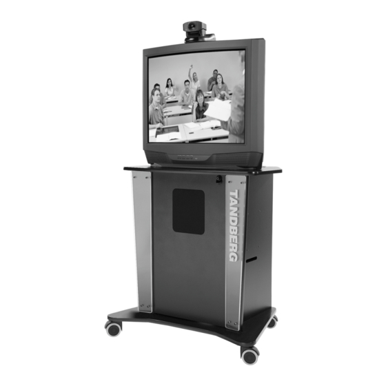
Page 7: Figure 1 Educator
Educator Panel Manual Content This manual is designed to assist you in the installation and configuration of the TANDBERG Educator . It assumes that users have a fundamental knowledge of the system. This manual is arranged in the order in which an Educator user will need the information. -
Page 8: System Description
TANDBERG Educator System Description Control Touch Panel Control A 10.4" color touch panel is used to control the entire TANDBERG Educator system. The touch panel with optional integrated instructor microphone is typically placed on a desk. Audio Audio Controls You can change the loud speaker sound level with the touch panel audio controls. You can also mute the microphones to have a private conversation during a distance education session. -
Page 9: Pc Presenter
Optional Equipment Document Camera The standard document camera is the TANDBERG Documentor camera with full touch panel control. Other cameras that can be used are the ELMO EVSeries with RS232 Control, Sony VID-PSeries withRS232 Control and the Wolfvision VZ series. The customer can also supply his own camera as long as it provides a composite video output. -
Page 10: Director Microphone
TANDBERG Trackers (automatic camera positioning) Up to 12 Trackers can be used by the system, allowing the user to request the Student Camera to focus on them. This option is only available for the Student Source with the WAVE camera configured. -
Page 11: Precautions
Unpacking The TANDBERG Educator is shipped in several crates. Each crate identifies its contents. We recommend that you store all packaging materials in case the need should arise to transport the system to another location. To repack the system, reverse the steps described to unpack it. -
Page 12: Room Configuration And Setup
TANDBERG Educator Room Configuration and Setup The Tandberg Application Module (TAM) has been designed to provide versatility for installation at any site. The following sections describe the Educator installation using TANDBERG carts in a typical room setup. If TANDBERG carts are not used, install the TAM and other equipment in a similar manner, as per site requirements. Continue with the cabling instructions that are applicable, no matter where the TAM is located. -
Page 13: Nam And Tam Location
TANDBERG Educator NAM and TAM Location The NAM and TAM electronics are pre-mounted into sleeve modules. The sleeve modules are designed to be installed by simply sliding into the shelf of the appropriate cart. Depending on the room configuration the following is recommended: •... -
Page 14: Nam And Tam Module Installation
TANDBERG Educator NAM and TAM Module Installation To install the NAM and TAM modules perform the following steps: Install the NAM module in the Student monitors/cart remove the back panel of the cart by using the key (provided with the cart) and pushing on the lock. -
Page 15: Cabling
TANDBERG Educator Cabling System cables are connected at the rear of the TAM, either directly to the Codec or to the interface panel. Connect cables to the TAM as required. Coil any excess lengths of cable and place at the bottom of the carts. -
Page 16: Cabling Configurations
TANDBERG Educator Cabling Configurations Figure 3 shows the system cabling when the TAM is located in the Instructor podium. Figure 4 shows the system cabling when the TAM is located in the Student cart. In this case, the AC power to the student peripherals is not controlled by a power control unit, but instead the AC power is connected to a power bar that is connected to the switched outlet of the TAM. -
Page 17: Instructor
1. Connect the INSTRUCTOR cable to the INSTRUCTOR connector on the TAM interface panel. If the TAM is not located close enough to the equipment, use a TANDBERG T510 extension cable. 2. Route the instructor cables to the instructor equipment and connect as follows: Connect the cable labeled CAM VID OUT to the VIDEO output connector of the camera. -
Page 18: Student
1. Connect the STUDENT cable to the STUDENT connector on the TAM interface panel. If the TAM is not located close enough to the equipment, use a TANDBERG T510 extension cable. 2. Route the student cables to the student equipment and connect as follows: Connect the cable labeled WAVE CAM to the WAVE camera. -
Page 19: Audioscience Microphone
TANDBERG Educator AudioScience Microphone 1. See Appendix 1: AudioScience Microphone. 2. Connect the AudioScience microphone cable to MIC 2 on the rear of the Codec. 3. An additional AudioScience microphone may be connected to MIC 3 on the rear of the Codec. -
Page 20: Network Terminating Units Nt1 And Nt384
TANDBERG Educator Network Terminating Units NT1 and NT384 (North America only) Install network terminating units when the site’s network provider ISDN BRI lines provides a U interface. The U interface of the unit is connected to the outside network, and the S/T interface of the unit is connected to the internal system network (Codec ISDN BRI connectors). -
Page 21: Document Camera
Document Camera The document camera option is a ELMO EV-Series with RS232 or a similar device. Installation instructions for the TANDBERG Documentor are supplied with the camera. Note: The Sony EVI-D30/31 document camera option is a custom configuration. 1. Place the document camera as appropriate. -
Page 22: Dvd Player
TANDBERG Educator If separate playback and record VCRs are used, connect as follows: 1. Place the VCRs on an equipment cart. 2. Connect the VCR cables to the TAM interface panel as follows: Connect the cable labeled TAM I/P VCR VIDEO IN to the VCR IN VIDEO connector of the interface panel. -
Page 23: Scan Converter
TANDBERG Educator Scan Converter (North America only) An optional scan converter can be installed within a peripherals cart as follows: 1. Place the scan converter on a shelf within the cart. 2. Connect the cable labeled TAM I/P VIDEO AUX IN to the VIDEO AUX IN 1 or 2 connector of the TAM interface panel. -
Page 24: Pressure Mats
TANDBERG Educator Pressure Mats 1. Install the pressure mats connector box with double- sided tape strips in a suitable location near the TAM. Place the pressure mats at desired locations within the room. The illustration shows some possible locations for the mats. -
Page 25: Tandberg Trackers
Touch and Talk Microphones (North America only) The installation of the Touch and talk microphones is discussed in document – D5012803 – By TANDBERG Inc. This document is supplied with the TNT equipment. -
Page 26: System Configuration
TANDBERG Educator System Configuration To configure the system, turn it ON by pressing SYSTEM ON in the upper left corner of the bezel. When power is applied to the system, the touch panel appears as follows: Figure 5 Touch Panel Opening Page The “Please Wait”... -
Page 27: System Set Up Button
TANDBERG Educator System Set Up Button Press SYSTEM SETUP and either the Main System Setup page or a key pad will appear on the screen. The key pad will only appear if the Password option has been selected in the System Setup page. To access the configuration pages when the password protection is active, you must enter the password on the key pad and press Enter. -
Page 28: Terminal Setup Page
TANDBERG Educator Terminal Setup Page Press TERMINAL SETUP to display the Terminal Setup page (see following figure). Different options will be displayed for configuring the ISDN-BRI/ PRI, Leased Line and External networks as shown in Figure 6. For each installation of the Educator... -
Page 29: Isdn-Bri Settings
TANDBERG Educator ISDN-BRI Settings Press ISDN-BRI in the CURRENT NETWORK panel of the Terminal Setup page to display this network’s control options. Figure 8 Terminal Setup ISDN-BRI Settings Page Switch Type Buttons Functions Enable Switch Type Enables (activates) the switch type that is displayed in the switch type window. -
Page 30: Advanced Setup
TANDBERG Educator Advanced Setup Buttons Functions Press the button to display the Advanced Call Setup screen. Select as many options as required from the advanced setup panel. Parallel Dial performs a parallel dial. If set to ON (illuminated), dialed channels will be connected in parallel when setting up a Bonding call. -
Page 31: Isdn-Pri Settings
Cable Length Use the arrow keys to specify the distance from the Educator2 to the CSU. The current length will be displayed in the white text box. Cascade Cable Length Use the arrow keys to specify the length of the cascading cable. -
Page 32: Advanced Setup
TANDBERG Educator Advanced Setup Buttons Functions Pressing this button displays the Advanced Configuration Screen. Select as many options as required from the advanced Setup Panel. Note: The Advanced Setup window has ‘green’ and ‘red’ indicators to show which settings are on or off. -
Page 33: External Network Settings
TANDBERG Educator External Network Settings Press External in the CURRENT NETWORK panel of the Terminal Setup page to display the External Network controls. Figure 10 External Setup Page Call Control Buttons Functions RS366 Dialing Enables RS366 dialing from the system, and is normally used together with network clocking. RS449/V35 compatible when the external equipment uses RS366 ports. -
Page 34: Leased E1/T1 Description
TANDBERG Educator Leased E1/T1 Description Press Leased E1/T1 in the CURRENT NETWORK panel of the Terminal Setup page to display the Leased E1/T1 network control options. Figure 11 Leased E1/T1 Page Network Type Buttons Functions E1/T1 Switch Type Enables the system type E1 (30 channels) or T1 (24 channels). E1 will be default for PAL versions and T1 will be default for NTSC versions. -
Page 35: Call Quality
TANDBERG Educator Call Quality Button Function Pressing this button displays the Call Quality Configuration Screen (see Figure 12). This allows the Codec to be set to make a specific type of call. The Codec will negotiate with the remote site using the given call parameters. -
Page 36: Ethernet H.323 & Ip Setup
TANDBERG Educator Ethernet H.323 & IP Setup Press Ethernet H.323 & IP Setup in the CURRENT NETWORK panel of the Terminal Setup page to display the controls for configuring the IP addresses. The controls are: Figure 13 Ethernet Diagnostic Setup Page... -
Page 37: Gatekeeper & Routing Settings
TANDBERG Educator Gatekeeper & Routing Settings Buttons Function The Codec will not use a gatekeeper and an IP-address must be used in order to make an H.323 call. Auto The Codec will automatically try to register on any available gatekeeper. If a gatekeeper responds to the request sent from the Codec within 30 seconds, this specific gatekeeper will be used. -
Page 38: Streaming
TANDBERG Educator Streaming Buttons Function Enable on Call Control This button allows you to enable streaming on the call Control/Status and Manual Dial pages. Start Streaming is started using Quick button “Start”. To stop streaming, press the Start button again. -
Page 39: Equipment Setup Page
TANDBERG Educator Equipment Setup Page The Equipment Setup page is the default page that appears when SYSTEM SET UP on the bezel is pressed. (The Equipment Setup page is active when the EQUIPMENT SETUP button is green.) A selected button goes from gray to green indicating that the source/option is active. -
Page 40: Student/Instructor Camera
, is installed. Parkervision Fully controlled from the Touch Panel. Activate Auto Tracking button TANDBERG WAVE/ Fully controlled from the Touch Panel. Set the camera’s brightness (Iris), White Balance by pressing Sony/Wave Setup. Sony EVI-D30/31 Camera type is automatically detected. -
Page 41: Sony Wave Camera Setup (Student, Instructor)
TANDBERG Educator Sony/Wave Camera Setup (Student, Instructor) Use the camera controls to manually set the Iris / Gain setting of the Sony EVI-D30/31 camera. This feature allows you to de-activate the default Auto-Iris setting on the camera and manually set it for difficult situations; for example, where the foreground and background are illuminated differently. -
Page 42: Document Camera
TANDBERG Educator Document Camera Pressing the Document Camera button opens a pop-up window in the right part of the screen. Select a document camera. The choices are as follows: Buttons Functions Wolfvision VZ-series Provides zoom, focus and iris controls. Elmo EV-400AF Provides zoom, focus, lighting and image controls. -
Page 43: Vcr Or Dvd Player
TANDBERG Educator VCR or DVD Player Pressing the VCR or DVD button opens a pop-up window in the right part of the screen. Select the applicable VCR or DVD player. Device Controls (DVD) • Sony DVD Touch panel provides play and transport controls. -
Page 44: Auxiliary Device #1
TANDBERG Educator Auxiliary Device #1 Press the Auxiliary Device #1 button to set the device attached to the AUX#1 port. Select the applicable auxiliary device from the pop-up window in the right part of the screen. The choices are as they appear in the following screen. -
Page 45: Auxiliary Device #2
TANDBERG Educator Auxiliary Device #2 Press the Auxiliary Device #2 button to set the device attached to the AUX#2 port. Select the applicable auxiliary device from the pop- up window in the right part of the screen. The choices are as they appear in the following screen. -
Page 46: Audio Setup Page
TANDBERG Educator Audio Setup Page Press AUDIO SETUP on the Main System Setup page to display the Audio Setup page. Use this page to view and change the settings and levels for each audio input and output. Telephone Add-on (North America only) -
Page 47: Audio Output Settings
TANDBERG Educator Audio Output Settings Audio Output Level Select to configure that audio output. Displays the corresponding audio level in dB. Audio 1 - Room Loud Speakers Audio 2 – Telephone Add-on Audio 3 - VCR Note: Selecting a particular Audio Output causes that output’s setup window to appear in the center of the screen. -
Page 48: Room Properties
TANDBERG Educator Room Properties The Room Properties feature allows you to set the optimization of the echo canceller to the acoustic size of the room. Hard walls, many windows etc. might require higher settings than expected. Carpets, curtains etc. might require a lower setting. -
Page 49: System Setup Page
Configures the type of monitor used in the system. Exit Returns to the Main Operating page. This can take several seconds as the system is communicating any changes to the related equipment. * See your TANDBERG Representative for more details. Installation and Configuration Manual - D50103-06... -
Page 50: External Control
Note. The supplied monitors are equipped with TANDBERD MIB (monitor interface box) and custom cabling. SVGA Custom Select this mode when the Educator is installed with TANDBERG MID (multi image display) hardware. When enabled an additional ‘setup’ button appears allowing configuration of the MID system. A separate document describes MID system operation. -
Page 51: Data Port Setup Page
Data Mode This mode provides a transparent data channel. This channel can be used for many different purposes such as file transfer, and application sharing. When using this mode, it is necessary to have a TANDBERG system at the remote site. -
Page 52: T120 Mode
TANDBERG Educator T120 Mode This mode provides a data channel that supports the T.120 standard for data communications. Using T.120 software such as Microsoft NetMeeting on a local PC, the user can communicate with other T.120 systems via the Educator Codec Test Page Press CODEC TEST on the System Setup Main page to display the Codec Test page. -
Page 53: Abbreviations
European Telecommunications Standards Institute Hum Filter IMUX Inverse Multiplexer ISDN Integrated Systems Digital Network Microphone Multi Subscriber Network Personal Computer Primary Rate Interface Touch and Talk SPID Service Provider Identification TANDBERG Applications Module Video Graphics Array Installation and Configuration Manual - D50103-06... -
Page 54: Appendix 1: Audioscience Microphone
AudioScience Microphone Parts Listing Before proceeding, please ensure that the following list of parts was received with your new AudioScience Microphone package. If any part is missing or damaged, contact your TANDBERG Representative to arrange for a replacement. Part Description... -
Page 55: Installation Considerations
4. The microphone cable should be routed from the microphone on the ceiling to the system on the floor in an aesthetic manner, such as within a conduit or wall “punch-out”. 5. The AudioScience microphone is currently limited for use on the TANDBERG Educator and other approved systems. Other applications will be documented, as they become available. -
Page 56: Selecting A Mounting Location
TANDBERG Educator Selecting a Mounting Location The mounting location of the AudioScience microphone can be determined through the application of three principles: 1. All desirable seating positions should be within 14 feet (5 meters) of the microphone capsule, with an unobstructed line of sight to the microphone capsule. -
Page 57: Assembly And Installation Instructions
TANDBERG Educator Assembly and Installation Instructions 1. Read the “Installation Considerations” on page 56 and proceed after all considerations have been understood and satisfied. 2. Read the guidelines for “Selecting a Mounting Location” on page 57 and select a mounting location. - Page 58 TANDBERG Educator 9. Push back the ceiling tiles located directly above the microphone unit. Route the microphone cable up from the hole in the top deflector, along one of the safety cables, to the ceiling. Use the supplied cable ties to attach the microphone cable to the safety cable.
-
Page 59: Appendix 2: The Tracker
TANDBERG Educator Appendix 2: The Tracker The Tracker is a hand held Infrared transmitter that allows user to request the student camera to focus on their location. Each Tracker has a specific Student camera preset allocated to it and hence the Tracker must be used from the location the camera preset will focus on. -
Page 60: Appendix 3: Installation And Setup, Educator/Tutor Extended Height Cart (Ehc-03) And Monitor Interface Box (Mib)
1. Unpack Extended Height Carts, equipment cabinet enclosure/s and monitors. 2. Install and fasten monitors on carts using the instructions supplied with TANDBERG monitors. 3. Locate, unpack and install the monitor RS232 printed circuit boards following the instructions supplied with the cards. -
Page 61: Optional Acrylic Shelf Installation
2. Install the MIB using the supplied bracket and screws to the rear of the cart (refer to images below). TAM Installation 1. Locate and unpack the Tandberg Applications Module (TAM). 2. Install the TAM unit within the bottom of the cabinet enclosure. -
Page 62: Power Bar Installation
TANDBERG Educator Power Bar Installation 1. Locate and unpack the power bar/s. One power bar is supplied with the Tutor Student system and two power bars are supplied with the Tutor Teaching or Educator system. 2. Install the power bar to the bottom rear of the cart. Insert the supplied long tie wraps within the holes on the cart and around the power bars. -
Page 63: Svga Connections
TANDBERG Educator 3. Connect cable/s T510C as shown in diagram below. If system is not equipped with an Instructor monitor cart omit the T510C-1320 cable connection. SVGA Connections 1. Connect the VGA cables as per diagram below. Installation and Configuration Manual - D50103-06... -
Page 64: Monitor Setup
TANDBERG Educator Monitor Setup Before continuing with this section make sure the system is completely connected and AC power can be applied. Once AC power is applied press SYSTEM ON (green button) located on the Touch Panel. At this point the monitors should have powered on. -
Page 65: Touch Panel Setup
TANDBERG Educator Touch Panel Setup 1. Press and hold the Touch Panel external System Setup button for about 3 seconds. 2. Next, press the System Setup button and the following page will appear 3. Press the Monitor Configuration button and the following popup page will appear to the far right of the screen.
Need help?
Do you have a question about the EDUCATOR2 and is the answer not in the manual?
Questions and answers