Table of Contents
Advertisement
Advertisement
Table of Contents
Troubleshooting

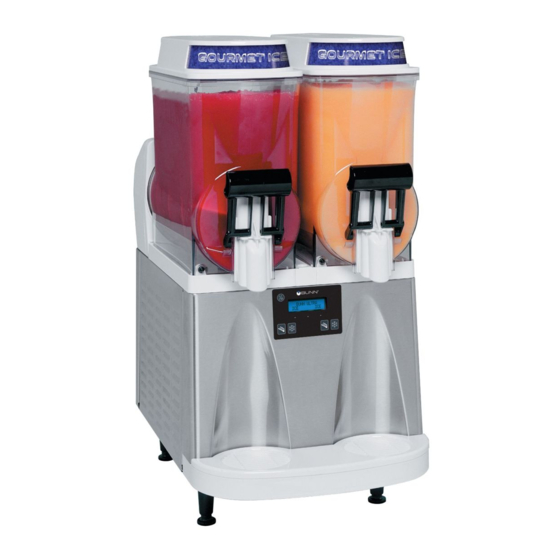
Related Manuals for Bunn Ultra


Summary of Contents for Bunn Ultra
- Page 1 BUNN TECHNICAL TRAINING ® Ultra...
-
Page 2: Table Of Contents
Thermistor ........................... 37 Compressor Windings ....................... 38 External Thermal Protector ....................38 PAF Error Messages ......................40 Ultra 1 Triac Map ......................... 40 Ultra 2 Triac Map ......................... 41 Ultra PAF Triac Map ......................42 © 2013 Bunn-O-Matic Corporation. All Rights Reserved... -
Page 3: Unit 1: Installation
Unit Objectives Given a realistic scenario depicting a new site install, the learner will be able to install and setup the ULTRA for cus- tomer turnover without error. Given a new machine, all the necessary tools and safety equipment, the learner will be able to install the ULTRA without error. -
Page 4: Site Requirements
• Dispenser performs better if not placed near any heating appliance that exhausts heat on and around dispenser. • Ultra-1 approx. dimensions (H 32 x W 8 x D 24.5) • Ultra-2 approx. dimensions (H 32 x W 16 x D 24.5) Plumbing (PAF Only) •... -
Page 5: Prepping For Install
Step 2: Unbox the machine and all the parts. Step 3: Place the machine in the desired location on the counter. Do not lift the Ultra by the drum(s). Step 3: Place the machine in the desired location on the counter. Do not lift the Ultra by the drum(s). -
Page 6: Electrical Install
Step 6: Press the seals firmly into Step 5: Install each hopper seal over the flange Step 4: Plug RCA cord into Ultra Step 6: Press the seals firmly into Step 5: Install each hopper seal over the flange Step 4: Plug RCA cord into Ultra place. -
Page 7: Laf Install
The Brix pump should be placed as close to the concentrate supply as possible. • The Brix pump mounting placement should be the same level or slightly higher than the concentrate BIB. • Ease of access to the brix pump and sanitize valve for sanitizing procedure. Bunn-O-Matic Corporation... - Page 8 LIQUID AUTOFILL KITS INTRODUCTION Installing Liquid Autofill Kits (Autofill ready Ultra-2) These instructions are for installing the Liquid Autofill Kits on Autofill ready ULTRA-2 cold drink dispensers. There are three different kits available: 37960.0000 ULTRA-2 Liquid Autofill Kit 120V with Separate Water Lines 37960.0001...
- Page 9 Early models with quick disconnect fittings, pointing down. quick disconnect fitting into the hole on follow steps 19 through 23. the hopper and secure with nut provided Late models with new hopper slide fitting with fitting. skip to step 24 through 26. Bunn-O-Matic Corporation...
- Page 10 155. The factory set point should not need any adjustment. 31. After confirming that both hoppers are reading about 250 for the threshold, proceed to the next screen to test the refill circuit. Ultra Training Manual 32. At the test refill screen, select yes.
- Page 11 32. At the test refill screen, select yes. 33. The Activate Valve screen will allow you to test the pumping and refill circuit. Press and hold the ULTRA button to activate the left refill system. Confirm that the left side is filling when the ULTRA button is pressed. Release the ULTRA button to stop the filling process.
-
Page 12: Unit 2: Setup
Unit Objectives Given a realistic scenario depicting a new site install, the learner will be able to install and setup the ULTRA for customer turnover without error. Given an installed machine, all the necessary tools and safety equipment, the learner will be able to set the machine up for initial operation. -
Page 13: User Interface
Press and hold for five seconds the “Gourmet” button to enter into the programming menus. “ULTRA” (left under display) When prompted by a selection from the menu to answer yes or no, the “ULTRA” switch is used to answer “NO” or (-) minus. -
Page 14: Setup
□ Day To Clean (Recommended) LAF Set Up Menus □ Delayed Refill □ Enable Refill ? (Ultra-1 Only) Set Thickness Setting the thickness changes the ice consistency, or torque of each auger. The factory default is 8 with a range of 1 to 16. - Page 15 “ICE” will change to “CHILL” during the night mode. During the night mode, the product will be kept chilled to below 35°F. “ICE” reading will return after night mode elapses. With “OFF” representing 12:00 AM, the operator can scroll to the times desired for the night time mode to begin and end. Bunn-O-Matic Corporation...
- Page 16 This can help the already frozen product from becoming diluted and not ready to serve. These delay and fill times are to be determined and set based on each application as desired by the end user. Enable Refill (Ultra-1 Only) This function will activate the Liquid Autofill function only in machines equipped with the LAF option.
-
Page 17: Product Preparation
Step 2: The delivery rate of the water ingredient is factory preset to 1 fl.oz. per second. Therefore, it is only necessary Step 3: Place the PAF on top of a fully assembled ULTRA taking care to align the PAF guide rails over the rollers on to adjust the delivery rate of the powdered granita mix. -
Page 18: Laf Liquid Concentrate Setup
Step 8: Turn on the water supply and the machine is now ready for start up and initial fill of the hopper. Ultra Training Manual... -
Page 19: Start Up
Step 3: Press and release the (ON/OFF) switch to power on the machine. Step 4: ULTRA with LAF option: Press and release the appropriate (ON/OFF) auger switch until the appropriate “Auger Refill On” mode is selected. This mode activates the motor and refill circuit in unison and will automatically maintain the level of product in the hopper to the probe level. -
Page 20: Unit 3: Machine Composition
achine oMposition Unit Objectives Given a realistic scenario in which the learner has access to the machine’s internal components the learner will un- derstand the composition and functions of the machine. Given a realistic scenario requiring the learner to access the internal components of the machine the learner will be able to remove the top motor covers, side panels and front control panel. -
Page 21: Exterior Overview
Removing the Enclosure The majority of the service work done to the ULTRA will require the service technician to access the inside of the machine. The ULTRA enclosure is comprised of two side panels, front control panel and two top motor covers to facilitate access to the refrigeration and electrical components. -
Page 22: Left Side Panel
Left Side Panel Removing the left side panel will give you access to the refrigerant solenoids, hot gas sensor/thermistor and optional LAF water valve/ULTRA-1 only. How to Remove The left side panel is attached by 2, 1/4 inch hex slotted screws on the underside. Remove or loosen the screws and the panel is now ready for removal by pulling downward and out. -
Page 23: Right Side Panel
Right Side Panel Removing the right side panel will give you access to the hood light relay, lamp circuit breaker, compressor relay, stepdown trans- former, condenser fan/ULTRA-2, compressor starting components and optional LAF water valve/ULTRA-2 only. How to Remove The right side panel is attached by 2, ¼ inch hex slotted screws on the underside. -
Page 24: Compressor
Compressor Electrtic Motor Type: The type of motor being used in the ULTRA-2 HP dispenser is known as CSR motor (Capacitive Start & Run). The CSR version uses a start and run capacitor with an external thermal protector. The start capacitor is in series with the compressor motor start winding. -
Page 25: Led Assembly
6 month PM = on/off Days to Clean = Thick Adjust = yes/no Switches = on/lockout Delay Refill = on/off Refill time = Delay time = Ad Message = enabled/disabled Enter asset # = (If applicable) Main Control Board Bunn-O-Matic Corporation... - Page 26 The amount of time for the delay is based on the cooling drum temperature. For instance, if the thermistors sense that both barrels, (one for Ultra-1), are above 50º F when the machine is powered up, the delay time is 1 min- ute.
- Page 27 Temperature Sensing System The Ultra uses a thermistor to monitor the actual temperature of each cooling drum. Night and Chill modes maintain 35º F, instead of the torque sensing board (product thickness).
-
Page 28: Unit 4: Preventive Maintenance
reventive aintenance Unit Objectives Given a realistic scenario depicting a machine requiring a preventive maintenance, the learner will be able to identify which elements of a component need to be serviced without error. Given a machine, all the necessary tools and safety equipment, the learner will be able to identify the components that need to be serviced for the PM. -
Page 29: Pm Parts
Prior to servicing the ULTRA: • The ULTRA has an optional menu setting that may alert the operator when Preventive Maintenance is due by displaying a message on the display, the message will read “Shaft Seal Maintenance Due”. The message will not shut down the machine if the service is not performed. - Page 30 Auger Shaft Assy Scroll to menu “PM Complete?” and answer “YES” to reset the reminder message “PM Due”. Lube about 1 ” of shaft and in the groove with BUNN P/N: 29563.0000 “Krytox” Lubricant Figure 3 Faucet Seal Figure 4...
-
Page 31: Unit 5: Troubleshooting
roubleshooting Unit Objectives Given a realistic scenario depicting one of several possible machine malfunctions, the learner will be able to effec- tively troubleshoot, diagnose and repair the malfunction before returning the machine to normal operation. Given a machine displaying an error or warning message, all the necessary tools and safety equipment, the learner will be able to access the programming and use component test menus as a tool to assist in the diagnosing process. -
Page 32: Service Tools
(TDS) of the product or water. The threshold 155 normally will not need to be adjusted on the Ultra machine but is mainly for geographical areas where naturally soft water is present or customers using water purifica- tion systems (reverse osmosis) on coffee equipment. -
Page 33: Temp & Torque Screen
Temp and Torque Screen Press and hold for five seconds the ULTRA and ICE hidden switches to display the TEMP & TORQUE. The tem- perature of each cooling drum and the hot gas temperature will toggle back and forth. The auger torque is displayed continuously during machine operation. -
Page 34: Warning Messages
I/O (ON/OFF) switch and allow the barrels or cooling drums to warm over 50°F. Scroll to the Cleaning Guide and perform the cleaning service. The barrels will warm to over 50°F when cleaned with warm water and the message will disappear. Clean Due Today CLEAN Due Now Ultra Training Manual... -
Page 35: Error Messages
Error Messages Bunn-O-Matic Corporation... - Page 36 The machine thinks the product thickness has reach the maximum and shuts off the compressor. The illustration below shows some of the other possible causes for a false reading from the torque sensor board. Ultra Training Manual...
-
Page 37: Torque Sensor Board
5vdc, replace thermistor. Resistance Check Disconnect the plug on thermistor leads and check resistance as indicated below. The indication must be: a) 5650 ohms @ 32° F ± 10% b) 2000 ohms @ 77° F ± 10% Bunn-O-Matic Corporation... -
Page 38: Compressor Windings
Step 1: Disconnect all electrical power to the BUNN ULTRA-2 HP. Step 2: Access compressor terminal pins and disconnect the wire leads going to the compressor pins. - Page 39 • Relay terminal 2 and 5: No continuity, broken coil, replace relay. • Relay terminal 1 and 2: No continuity, contacts are open, replace relay. Start Capacitor Start Capacitor: BUNN P/N# 39804.0004 Rating: 243-292 MFD 165V 50/60HZ Disconnect the start capacitor from the system. Remove the bleed resistor. Use a capacitance meter to measure the capacitance.
-
Page 40: Paf Error Messages
Flashes On/Off at 50% duty cycle Low product level in Powder Autofill hopper. Two flashes about every 2 seconds Ultra/Powder Autofill probe circuit open. Three flashes about every 2 seconds Powder Autofill hopper not in place. Four flashes about every 2 seconds Ultra refill exceeded 5 minutes. -
Page 41: Ultra 2 Triac Map
Ultra 2 Triac Map (CBA with Real Time Clock) 1. TH6 = Left Refrigerant Solenoid Valve 2. TH5 = Compressor Relay 3. TH4 = Condensor Fan Motor 4. TH3 = Right Refrigerant Solenoid Valve 5. TH2 = Left Auger Motor 6. -
Page 42: Ultra Paf Triac Map
Ultra PAF Triac Map 1. Right Fill Valve (TH1) 2. Left Fill Valve (TH2) Ultra Training Manual...
Need help?
Do you have a question about the Ultra and is the answer not in the manual?
Questions and answers