Table of Contents
Advertisement
Quick Guide
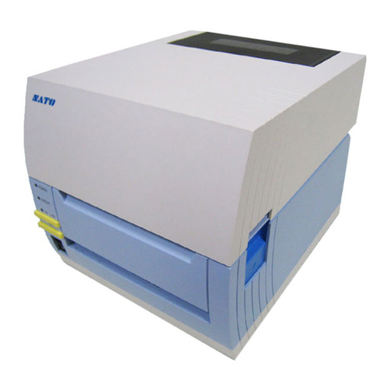
Label Printer
CT400i Series
CT400iDT Series
Thermosensitive type
203dpi/305dpi/600dpi
* Be sure to use SATO genuine parts
(labels, ribbons).
Thank you for purchasing
the SATO CT400i Series
barcode printer. Please
read this manual carefully
to ensure you understand
the CT400i Series
functions and how to
operate it properly.
CT400iTT Series
Thermal transfer type
203dpi/305dpi/600dpi
Advertisement
Table of Contents

Related Manuals for SATO CT400i Series


Summary of Contents for SATO CT400i Series
- Page 1 CT400i Series read this manual carefully to ensure you understand the CT400i Series functions and how to operate it properly. CT400iTT Series Thermal transfer type 203dpi/305dpi/600dpi CT400iDT Series Thermosensitive type 203dpi/305dpi/600dpi * Be sure to use SATO genuine parts (labels, ribbons).
- Page 2 FCC WARNING You are cautioned that changes or modifi cations not expressly approved by the party responsible for compliance could void your authority to operate the equipment. This device complies with Part 15 of the FCC Rules. Operation is subject to the following two conditions: (1) this device may not cause harmful interference, and (2) this device must accept any interference received, including interference that may cause undesired operation.
-
Page 3: Safety Precautions
• Do not use other than the accidentally drinking it. If the specified voltage. Doing so fluid is drunk, immediately could result in fire or electric consult with a physician. shock. Version 1 December 10, 2007 Q02073000 ©2007 SATO CORPORATION... - Page 4 Safety Precautions Caution Do not place in areas with high humidity Power cord Opening and closing the thermal head Do not place the printer in • Keep the power cord away from • When opening or closing the • areas with high humidity or hot devices.
-
Page 5: Accessories Check
Accessories Check The following items are packed together with the main unit in the box. Be sure to check to make sure nothing is missing. If something is missing, contact the store or dealer where you purchased the product. ¡ ¡... -
Page 6: Names Of Parts
Names of Parts Printer unit [unit exterior] ¡Window ¡Top cover ¡Label discharge outlet ¡Front cover ¡Opening lever ¡Operation panel [Back (USB + LAN interface) ¡USB interface ¡LAN interface ¡DC input power terminal (Power connector) ¡I/F Cover [Back (USB + RS-232C interface) ¡USB interface ¡RS-232C interface ¡Interface board... - Page 7 Names of Parts When top cover is opened [For CT400iDT Series] ¡Thermal head ¡Paper holder ¡Paper sensor ¡Platen roller ¡Paper holder slide lever [For CT400iTT Series] ¡Ribbon unit ¡Paper holder ¡Paper sensor ¡Platen roller ¡Paper holder slide lever...
- Page 8 Names of Parts When top cover is opened [Cutter Type] ¡Cutter top knife ¡Paper holder ¡Paper sensor ¡Platen roller ¡Paper holder slide lever (When front cover is open) ¡Cutter bottom knife ¡Cutter unit [Separation Type] ¡Paper holder ¡Paper sensor ¡Platen roller ¡Paper holder slide lever ¡Backing paper...
-
Page 9: Operation Panel
Names of Parts [Operation Panel] ¡ [POWER] lamp Illuminates (green) when the power switch is on. ¡ [ERROR] lamp Illuminates or flashes (red) when an error occurs. ¡ [ON LINE] lamp Illuminates (green) when reception is possible. ¡ [ON LINE] key This is press to stop/restart and to terminate data reception. - Page 10 Loading the Roll Paper [Continuous, Cutter, Linerless types] Press down the opening lever (1) on the right side of the printer to release the lock and open the top cover (2). While pressing the paper holder slide lever (1), adjust the paper holder to match the paper size (2).
- Page 11 Loading the Roll Paper [Continuous, Cutter, Linerless types] Close the top cover. At this time, press on the top where shown by the arrows to close the cover until you hear the lock engage. (1) Press the [FEED] key to feed the leading edge of the paper.
- Page 12 Loading fan-folded paper [Continuous, Cutter types] Open the window from the back edge. Window Press down on the open lever (1) on the right side of the printer to release the lock and then open the top cover (2). Pass the paper through the opened window.
- Page 13 Loading fan-folded paper [Continuous, Cutter types] While pressing the paper holder slide lever (1), adjust Paper sensor the paper holder to match the paper size (2). After pulling out the paper, pass it through the paper sensor. Close the top cover. At this time, press on the top where shown by the arrows to close the cover...
- Page 14 Loading Roll Paper [Separator] Press down on the open lever (1) on the right side of the printer to release the lock and then open the top cover (2). Open the front cover forward. While pushing on the [PUSH DOWN] mark on the separator unit, tilt it forward (1) to open the separator unit (2).
- Page 15 Loading Roll Paper [Separator] Peel off labels to expose 15 cm of only the backing paper and then load the paper into the paper holder. After pulling out the paper, pass it through the paper sensor. Pass the backing paper between the separator unit and the platen roller.
- Page 16 Loading Roll Paper [Separator] Close the top cover. At this time, press on the top where shown by the arrows to close the cover until you hear it lock closed. (1) Press the [FEED] key to feed the leading edge of the paper.
-
Page 17: Printing Position Adjustment
Printing Position Adjustment ▲ Printing Standard Position The printing standard position when using labels is the top of the label. The printing standard position when using fan folded paper is the top of the match mark on the back of the fan folded paper. -
Page 18: Cut Position Adjustment
Cut Position Adjustment ▲ Label Cut The cut position when using labels is the designated cut position between labels on the blank area (the area where there is only backing paper). Labels Backing paper Cut position (Fig. 1) (Fig. 2) If the cut position is not the prescribed position, open the top cover and use the Philips head end of the dial screwdriver attached to the printer unit to adjust the cut position. -
Page 19: Loading The Carbon Ribbon
Loading the Carbon Ribbon [Loading the Carbon Ribbon] Press down on the open lever (1) on the right side of the printer to release the lock and open the top cover (2). [PULL] mark Pull the ribbon unit’s [PULL] mark to pull the ribbon unit forward. - Page 20 Loading the Carbon Ribbon [Loading carbon ribbons with a width greater than 92 mm] After setting the carbon ribbon in the right side of the ribbon supply unit (1), press the core guide (2). Ribbon supply unit core guide After setting the ribbon core in the right side of the ribbon windup unit (1), press the core guide (2).
- Page 21 Loading the Carbon Ribbon [Loading carbon ribbon with a width under 76 mm] For carbon ribbon with a width of 76 mm or 59 mm, set the ribbon adapter hooks at the bottom. From this state, turn the hooks in the direction shown by the arrow to set it at the bottom.
- Page 22 Loading the Carbon Ribbon Set the ribbon unit in the top cover and return the cover to its original position. Closing the top cover after closing the ribbon unit could prevent the top cover from closing properly. Always Caution put the ribbon unit in the top cover. For the cutter type, be careful not to Paper sensor cut your hand on the top cutter knife...
-
Page 23: Connecting To A Computer
Connecting to a Computer [Standard Interface] ¡USB + LAN type USB interface LAN interface (1)When using a USB interface, set DSW 1-8 inside the front cover to OFF. When using a LAN interface, set DSW 1-8 inside the front cover to ON. -
Page 24: Ieee 1284 Interface
Connecting to a Computer [Extension Interface(Option)] ¡IEEE 1284 interface IEEE 1284 interface (1)When using an IEEE 1284 interface, set DSW 3-1 of the circuit board on the bottom of the printer to ON. (2)To set the printing support for the IEEE 1284 interface setting, set DSW3-2 of the circuit board on the bottom of the printer. -
Page 25: Bluetooth Interface
Connecting to a Computer (1)When using the wireless LAN2 interface, set DSW 3-1 of the circuit board on the bottom of the printer to ON. (2)When setting the wireless LAN2 interface setting to the reception mode, set DSW 3-2 of the circuit board on the bottom of the printer. -
Page 26: Turning On The Power
Turning On the Power Plug the AC adapter/power cord into the printer and turn on the power. [Power Setting] When installation is completed, set the power as shown below. Connect the power cord to the AC adapter. The plug of the included power cord is a 3-pronged plug. -
Page 27: Turning Off The Power
Turning On the Power [Turning On the Power] Turn on the power switch at the front POWER lamp of the printer. ERROR lamp Switch it to the “ ” symbol. ONLINE lamp [ONLINE] key When the power switch is turned on, Power switch the POWER lamp will illuminate. - Page 28 Printing Operation Confirmation and Error Number Display [Printer Status Print] This prints the status of the printer. The current settings information is printed, so check the settings printout. Turn on the power while pressing the [FEED] key. [ON LINE] key The buzzer will sound, so then press the following key.
-
Page 29: Dip Switch Settings
Printing Operation Confirmation and Error Number Display [Dip Switch Settings] Suitable settings have been made to match the printer’s operating environment, but in the event the settings are different, please reset the dip switches. * A detailed explanation of the dip switches is given on the explanation sticker affixed to the printer. - Page 30 Printing Operation Confirmation and Error Number Display ¡ Dip Switch Settings Table DSW2 (RS-232C Interface Settings) Only for the USB + RS-232C type To change the dip switch DSW2 settings to make the RS-232C interface settings, set them as shown below. (1) Turn off the printer power and disconnect the power cord.
- Page 31 USB + LAN type Function Explanation Not used Normally OFF Interface settings USB interface (DSW1-8 OFF) DSW3-2 Printing port SATO port Standard printing port LAN interface (DSW1-8 ON) DSW3-2 Reception mode Periodic response status ENQ response status USB + RS-232C type Function...
-
Page 32: Error Messages
Printing Operation Confirmation and Error Number Display ¡ Error Messages Error Cause Resolution Method Code FLASH ROM read/write overflow Contact the store, dealer, or support center. or write count overflow. Defective circuit board Contact the store, dealer, or support center. EEPROM error Contact the store, dealer, or support center. -
Page 33: Basic Specifications
Max. folded height: 100 mm (Supplied from outside the printer.) Refer to “Fan-folded Paper Settings.” / page 12 Carbon ribbon Only use carbon ribbon manufactured and specified by SATO. Width 45, 59, 76, 92, 111mm The carbon ribbon width should be wider than the paper being used. - Page 34 Basic Specifications Weight 3.0 kg (standard) Excluding AC adapter,battery Power supply AC adapter AC 100 to 240V (1.5A) 50/60 Hz Input voltage DC 25V (2.0A) Output voltage Print ratio 30% 180VA 120W Power consumption Maximum 280VA 180W During standby 30VA Environmental Operation ambient temperature: 5 to 35°C conditions...
- Page 35 Basic Specifications Contained fonts 5 × 9 dots (alphanumeric, symbol) Standard 17 × 17 dots (alphanumeric, symbol) 24 × 24 dots (alphanumeric, symbol) 48 × 48 dots (alphanumeric, symbol) 48 × 48 dots (alphanumeric, symbol) Outline font (alphanumeric, symbol) OCR-A 15×22 dots OCR-A 22×33 dots OCR-A 44×66 dots (alphanumeric, symbol)
Need help?
Do you have a question about the CT400i Series and is the answer not in the manual?
Questions and answers