
Subscribe to Our Youtube Channel
Related Manuals for SHENZHEN ENCOM ELECTRIC TECHNOLOGIES CO. EDS1000 series


Summary of Contents for SHENZHEN ENCOM ELECTRIC TECHNOLOGIES CO. EDS1000 series
- Page 1 ISO9001:2000 Quality Management System Authentication CE Authentication EDS1000 series 0.4-75KW U n i v e r s a l i n v e r t e r V e r . 3 . 0 SERVICE MANUAL SHENZHEN ENCOM ELECTRIC TECHNOLOGIES CO.,LTD.
- Page 2 Thank you for purchasing EDS1000 series multi-function universal inverter from our company Shenzhen Encom Electric Technologies CO., LTD. 1. EDS1000 series can fulfill all kinds of demand for general-purpose inverter by advanced control manner which make high torque,high precision and wide-range speed regulation drive be available.
- Page 3 Print version:V3.0-A11 rewinding of the inverter, to keep constant tension of winding and rewinding cable. Drawing machine can divide into large drawing machine, medium drawing machine, slender drawing machine and micro drawing machine other four, composes of drawing and taking-up two parts. To improve the quality of cable and lower the cost, drawing machine is general from single frequency control to dual-frequency control, and now most of the dual-frequency control is generally used external PID...
- Page 4 Assembling wiring, parameter setting, troubleshooting and daily maintenance notices are available in this manual. To make sure that you can correctly assemble and operate EDS1000 series inverters to exert their excellent performance, please read this user manual detailed before you assemble the device and conserve the manual appropriately before the end-user get them.
-
Page 6: Table Of Contents
CONTENTS Safety information and use n otice points 1.1 safety precautions 1.2 use range 1.3 use notice points 1.4 scrap notice points Type and specification of the inverter 2.1 incoming inverter inspect 2.2 type explanation 2.3 nameplate explanation 2.4 series type explanation 2.5 appearance and parts name explanation 2.6 outer size and gross weight 2.7 outer size of key board and its fixing box... - Page 7 3.6.2 explanation for control panel terminal 3.6.3 analog input output terminal wiring 3.6.4 communication terminal wiring 3.7 installation guide for anti-jamming 3.7.1 restraining to noise disturbance 3.7.2 locale wiring and earthing 3.7.3 relation of long-distance wiring and current leak and the countermeasure 3.7.4 installation demand for electromagnetic on-off electronic device Run an d op eration e xplanation for i n verter...
- Page 8 6.2 start-up, stop, braking function parameter group:F1 6.3 assistant run function parameter group:F2 6.4 Closed-loop run control parameter group: F3 6.5 simple PLC run function parameter group:F4 6.6 terminal function parameter group:F5 6.7 swing frequency parameter group:F6 6.8 frequency-provision parameter group:F7 6.9 motor and vector control parameter group:F8 6.10 protection function parameter:F9 6.11 failure record function parameter:Fd...
- Page 9 Serial port RS485 communication protocol Appendix1 EDS1100 drawing machine inverter manual Appendix2 The manual of middle frequency inverter Appendix3 Modus communication protocol(need customized special process) Appendix4 Braking resistance...
-
Page 10: Safety Information And Use Notice Points
www.enc.net.cn/en Tel/Fax:86-755-26984485/26985120 1 Safety information and use notice points 1 Safety information and use notice points In order to ensure the safety of your personal and equipment, before using the inverter, please read this chapter of contents conscientiously. 1.1 Safety p recautions There are three kinds of safe relevant warnings in this service manual, they are as follows: This symbol briefs on: If does not operate on request, may make the body... -
Page 11: Use Range
1.3 Use notice points (1) EDS1000 series inverter is voltage-type inverter, so temperature, noise and vibration slightly increasing compared to power source running when using, belongs to normal phenomenon. - Page 12 www.enc.net.cn/en Tel/Fax:86-755-26984485/26985120 1 Safety information and use notice points (5) For hoist and great inertia load, etc., the inverter would shut off frequently due to over-current or over-voltage failure, in order to guarantee normal work, should consider choosing proper brake package. (6) Should switch on/off the inverter through terminal or other normal order channels.
-
Page 13: Scrap Notice Points
www.enc.net.cn/en Tel/Fax:86-755-26984485/26985120 1 Safety information and use notice points EDS1000 After wiring, short-circuit U, V, W to measure insulation resistance. EDS2000 EDS1000 motor Grounding part Megohm meter Fig.1-1 motor insulation measure Fig.1-2 capacitor at output side forbidden 1.4 Scrap notice points When disposing scrap inverter and its parts, please note: (1) The unit: please discard as industrial useless. -
Page 14: Type And Specification Of The Inverter
www.enc.net.cn/en Tel/Fax:86-755-26984485/26985120 2 Type and specification of the inverter Type and specification of the inverter 2.1 Incoming inverter inspect (1) Check if there is damage during transportation and inverter itself has damage or fall-off parts. (2) Check if parts presented in packing list are all ready. (3) Please confirm rated data of the inverter is in line with your order requirement. -
Page 15: Series Type Explanation
www.enc.net.cn/en Tel/Fax:86-755-26984485/26985120 2 Type and specification of the inverter 2.4 Series type explanation Table 2-1 series type explanation Input Inverter type Rated power Rated output Adapted motor (G: general with constant torque: voltage (KVA) current (A) (KW) P: special for blower water pump) EDS1000-2S0004 Single EDS1000-2S0007... -
Page 16: Appearance And Parts Name Explanation
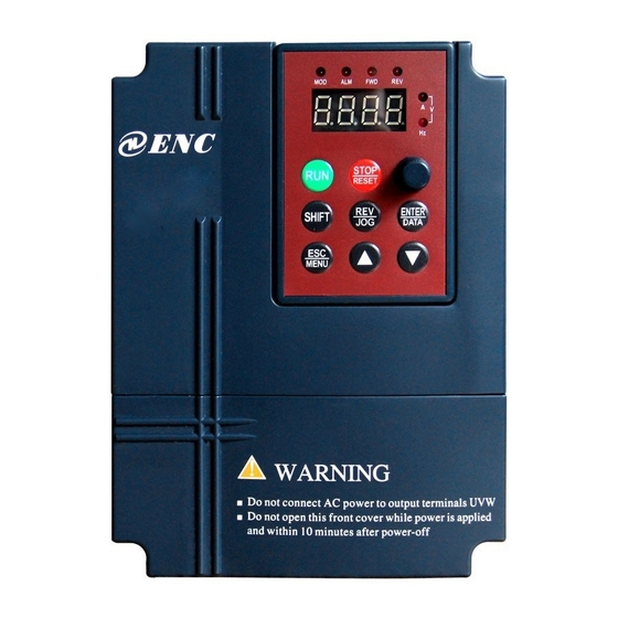
www.enc.net.cn/en Tel/Fax:86-755-26984485/26985120 2 Type and specification of the inverter 2.5 Appearance and parts name explanation digital LED display LED display potentiometer keypad digital potentiometer Upper cover plate keypad connection terminal Control cable nameplate nameplate inlet ventilation hole bottom fitting hole Power supply input end Control cable inlet Power supply input end,... - Page 17 www.enc.net.cn/en Tel/Fax:86-755-26984485/26985120 2 Type and specification of the inverter Fig.2-4 Fig.e outer dimension Fig.2-4 Fig.f outer dimension Table 2-2 EDS1000-2S0004~EDS1000-4T0750P mounting size Fixi apert Inverter type G.W. (G: general; P: special) (mm) (mm) (mm) (mm) (mm) (mm) (kg) EDS1000/1200/1300-2S0004 EDS1000/EDS1100/1200/1300-4T0007G 110 160 125 170 123.2 135.5 1.5 Fig a EDS1000/1200/1300-2S0007 EDS1000/EDS1100/1200/1300-4T0015G...
-
Page 18: Outer Size Of Key Board And Its Fixing Box
www.enc.net.cn/en Tel/Fax:86-755-26984485/26985120 2 Type and specification of the inverter Table 2-2 EDS1000-7T0185G~EDS1000-7T1320G mounting size Fixing Inverter type aperture Fig. (mm) (mm) (mm) (mm) (mm) (mm) EDS1000-7T0110G/0150P 252.7 Fig e EDS1000-7T0150G/0185P EDS1000-7T0185G/0220P EDS1000-7T0220G/0300P Fig d EDS1000-7T0300G/0370P EDS1000-7T0370G/0450P EDS1000-7T0450G/0550P Fig d EDS1000-7T0550G/0750P EDS1000-7T0750G/0900P EDS1000-7T0900G/1100P Fig d... -
Page 19: Product Technic Index And Spec
www.enc.net.cn/en Tel/Fax:86-755-26984485/26985120 2 Type and specification of the inverter Fig.2-7 EN-KB6 outer size Fig.2-8 EN-KB6 hole size Product technic index and spec item Item description 3 phase 690V grade, 3 phase 690V ,50Hz/60Hz; 3 phase 380V grade, 3 phase 380V ,50Hz/60Hz; Rating volt., frequency 1 phase 220V grade, 1 phase 220V ,50Hz/60Hz Input... - Page 20 www.enc.net.cn/en Tel/Fax:86-755-26984485/26985120 2 Type and specification of the inverter Automatic torque boost, manual torque boost Torque boost 0.1%~12.0% Set rating frequency randomly at range of 5~400Hz,can choose constant torque, degressive V/F curve (volt. frequency torque 1, degressive torque 2, degressive torque 3 characteristic) and user-defined V/F in total 5 kinds of curve 2 modes: straight line accelerating decelerating and...
- Page 21 www.enc.net.cn/en Tel/Fax:86-755-26984485/26985120 2 Type and specification of the inverter Over-current protection, over-voltage protection, Protection function lack-voltage protection, over-heat protection, over-load protection, etc. brake subassembly, remote-control keypad, Fitting parts connecting cable for remote-control keypad etc. indoor,not bare to sunlight,no dust, no corrosive Use ambient gas, no flammable gas, no oil fog, no vapor, no water drop or salt etc.
-
Page 22: Installation And Wiring
www.enc.net.cn/en Tel/Fax:86-755-26984485/26985120 3 Installation and wiring Installation and wiring 3.1 Installation ambient 3.1.1 Demand for installation ambient (1) Installed in drafty indoor place, ambient temperature within -10ºC~40ºC, need external compulsory heat sink or reduce the volume if temperature exceeds 40ºC. (2) Avoid installing in place with direct sunlight, much dust, floating fibre and metal powder. -
Page 23: Parts Disassembly And Installation
www.enc.net.cn/en Tel/Fax:86-755-26984485/26985120 3 Installation and wiring Leading divider Fig. 3-2 mounting of multiple inverters 3.2 Parts disassembly and installation 3.2.1 Key board disassembly and installation Mounting claw (1) disassembly Let the forefinger press finger inlet on the keypad,depress fixing flexible plate Hook on the top lightly, draw it outward, then Mounting claw... -
Page 24: Wiring Notice Points
www.enc.net.cn/en Tel/Fax:86-755-26984485/26985120 3 Installation and wiring 2> put the mounting claw into relevant hole on the unit body and then press downward in force, see fig. 3-4-a. Metal cover disassembly and installation (1) disassembly First take off 2 screws at sides of the cover and move it a bit outward horizontally, then tilt it at 15 degree and draw it outward at direction shown in right figure, now you can take the cover off. -
Page 25: Main Loop Terminal Wiring
www.enc.net.cn/en Tel/Fax:86-755-26984485/26985120 3 Installation and wiring (1)Before wiring, assure power supply is cut off completely for 10 minutes and all LED indicator light extinguished. (2)Before internal wiring, confirm that DC volt. Between main loop end P+ and P- fall down to below DC36V. danger (3)Wiring can only be done by professional person trained and qualified. -
Page 26: Main Loop Terminal Wiring
www.enc.net.cn/en Tel/Fax:86-755-26984485/26985120 3 Installation and wiring (4) Magnetic control conductor only be applied to power supply control and don’t apply magnetic control conductor to controlling on/off of the inverter (5) Input side EMI filter Can use EMI filter to inhibit high-frequency conduction disturbance and emission Isolation switch... - Page 27 www.enc.net.cn/en Tel/Fax:86-755-26984485/26985120 3 Installation and wiring Table 3-1 main loop input output terminal description Main loop terminal Adapted type Function description name Zero wire live wire EDS1000-2S0004~ DC volt. Positive end DC volt. negative end EDS1000-2S0015 L1 L2 P+ P- U V W E U,V,W 3 phase AC output end...
- Page 28 www.enc.net.cn/en Tel/Fax:86-755-26984485/26985120 3 Installation and wiring R, S, T 3 phase AC 380V input terminal DC side voltage positive T P P+ P- U V W E EDS1000-4T0185G terminal EDS1000-4T0550G Reserved terminal for exterior DC reactor EDS1000-4T0220P DC side voltage negative EDS1000-4T0750P terminal U,V, W...
-
Page 29: Basic Running Wiring Diagram
www.enc.net.cn/en Tel/Fax:86-755-26984485/26985120 3 Installation and wiring Basic running wiring diagram Adapted type:EDS1000-2S0004~2S0037 EDS1000-4T0007~4T0015G EDS1000-4T0022G~EDS1000-4T0750P Braking unit Braking resistance (external,fitting part) (external,fitting part) breaker 3 phase R(L1 220V AC) 380V S(L2 220V AC) 50/60Hz Forward run/stop EDS1000 Reverse run/stop DC amperometer Multi-function 1 4-20mA current signal Multi-function 2... -
Page 30: Control Loop Collocation And Wiring
www.enc.net.cn/en Tel/Fax:86-755-26984485/26985120 3 installation and wiring 3.6 Control loop collocation and wiring 3.6.1 Location&function of terminal and slide switch: For location of terminal and slide switch on the CPU board, please see Fig.3-10. Function description of terminal provided for the user, please see Table 3-2, function and setup description of slide switch, please see Table 3-3,... -
Page 31: Explanation For Control Panel Terminal
www.enc.net.cn/en Tel/Fax:86-755-26984485/26985120 3 installation and wiring Table 3-3 function description of slide switch provided for user Symbol Function Setting Factory default :0~5V voltage signal; YCI: 5V/10V voltage input mode 0~5V :0~10V voltage signal selection :0~10V voltage signal ; VCI:5V/10V voltage input mode 0~10V :voltage signal selection... - Page 32 www.enc.net.cn/en Tel/Fax:86-755-26984485/26985120 3 installation and wiring Multi-function input 5 end function description. X7, X8 can be set as Multi-function input 6 H-speed impulse input port, Input impedance of X7, for detailed see Chapter 6 X8 input channel: Multi-function input 7 Section 6.6 terminal R=2KΩ...
- Page 33 www.enc.net.cn/en Tel/Fax:86-755-26984485/26985120 3 installation and wiring Accept analog voltage Input voltage range: input,0~5V or 0~10V 0~10V (input optioned by slide switch impedance: 70KΩ) Analog value input VCI resolution: 1/1000 JP8,factory default is 0~10V. (reference ground: GND) Provide analog voltage/current output,can express 6 kinds of parameter see F5.17 Current output range:...
-
Page 34: Analog Input Output Terminal Wiring
www.enc.net.cn/en Tel/Fax:86-755-26984485/26985120 3 installation and wiring “*” terminal is for the manufacturer, user can’t use. (5) RS485 terminal and JP15 function description as table 3-5 Table 3-5 CPU board RS485 terminal function table item symbol name Function description spec 485 difference signal positive end For standard RS-485 RS485+ RS485... - Page 35 www.enc.net.cn/en Tel/Fax:86-755-26984485/26985120 3 installation and wiring (2) CCI terminal accepts analog signal input,slide switch decide to input voltage(0~10V) or input current(4~20mA),wiring mode as follows: CCIcurrent input EDS1000 +10V 0~+10 0/4~20mA Or 0~+5V CCI volt. input ― Shielded wire close end grounded 0~10V Fig.3-12 CCI terminal wiring diagram (3) YCI terminal accepts analog voltage signal input,wiring mode as follows:...
-
Page 36: Communication Terminal Wiring
www.enc.net.cn/en Tel/Fax:86-755-26984485/26985120 3 installation and wiring 2> when YCI input voltage is 0~5V: 2.5V -high limit frequency + high limit frequency (REV) (FWD) f(Hz) (4) wiring of analog output terminals AO1, AO2 analog output terminals AO1, AO2 connected to analog meter and kinds of physical data can be indicated, thereinto AO1 can output current (4~20mA) or voltage (0~10V) decided by slide switch JP6. - Page 37 www.enc.net.cn/en Tel/Fax:86-755-26984485/26985120 3 installation and wiring A(485+) 1(485+) EDS1000 Device with 3(485-) B(485-) RS485 RS485 interface (E)PE or EDS1000 Fig.3-15 communication terminal wiring (2) To connect remote control keypad, you can connect plug of remote control keypad to RS485 directly. No need to set any parameter, inverter local keypad and remote control keypad can work at one time.
-
Page 38: Installation Guide For Anti-Jamming
www.enc.net.cn/en Tel/Fax:86-755-26984485/26985120 3 installation and wiring power supply. 2> Apply magnetic circle on the communication wire. 3> Reduce inverter carrier wave frequency properly. (1) When form the network only by inverters, you must set local address parameter F2.15 of the mainframe EDS1000 to 0. (2) For programming of RS485 interface,please refer to appendix note communication protocol. - Page 39 www.enc.net.cn/en Tel/Fax:86-755-26984485/26985120 3 installation and wiring (2) noise spread road ⑧ ② ② ⑥ ⑤ ③ power supply inverter Wireless set meter ④ ⑦ sensor ⑤ motor ① Fig.3-19 noise disturbance spread road sketch (3) basic countermeasure for suppressing disturbance Table 3-7 disturbance suppressing countermeasure table Noise spread...
-
Page 40: Locale Wiring And Earthing
www.enc.net.cn/en Tel/Fax:86-755-26984485/26985120 3 installation and wiring Keep device and signal wire prone to disturbance from the inverter. Should use shielded signal wire, shielding layer single end earthed and try best to keep away from the inverter and its input, output wire. If signal wire must intersect strong power cable, must keep them in real intersection and avoid parallel. -
Page 41: Relation Of Long-Distance Wiring And Current Leak And The Countermeasure
www.enc.net.cn/en Tel/Fax:86-755-26984485/26985120 3 installation and wiring 3.7.3 Relation of long-distance wiring and current leak and the countermeasure High-order harmonic will form between-line leak current through distributing capacitor and to-earth leak current when long-distance wiring between inverter and motor commence. Can adopt following method to suppress: (1) install ferrite magnetic circle or output reactor at inverter output side. -
Page 42: Run And Operation Explanation For Inverter
www.enc.net.cn/en Tel/Fax:86-755-26984485/26985120 4 Run and operation explanation for inverter 4 Run and operation explanation for inverter 4.1 Run of inverter 4.1.1 Running order channels There are 3 kinds of order channel for controlling run action of the inverter such as run, stop, jog etc.: 0: keypad STOP Control by key... -
Page 43: Work State
www.enc.net.cn/en Tel/Fax:86-755-26984485/26985120 4 Run and operation explanation for inverter 4.1.3 Work state Work state of EDS1000 is classified as waiting state and running state: waiting state: If there is no running command after the inverter electrified or after stop command during running state, the inverter enters into waiting state. running state: the inverter enters into running state after receiving run command. - Page 44 www.enc.net.cn/en Tel/Fax:86-755-26984485/26985120 4 Run and operation explanation for inverter 0: jog run Upon receiving jog run command (for instance, press the key on keypad) during waiting state, the inverter run at jog frequency (see function code F2.06~F2.08). 1: closed-loop run The inverter will come into closed-loop run mode when closed –loop run control effective parameter is set(F3.00=1).
-
Page 45: Operation And Use Of Key Board
www.enc.net.cn/en Tel/Fax:86-755-26984485/26985120 4 Run and operation explanation for inverter 4.2 Operation and use of key board 4.2.1 Keypad layout Keypad is main unit for receiving command, displaying parameter. Outer dimension of EN-KB6 is as Fig.4-2: Failure alarm indicator light Forward run indicator light Reverse run indicator light Mode indicator light Current unit(A) -
Page 46: Led And Indicator Light
www.enc.net.cn/en Tel/Fax:86-755-26984485/26985120 4 Run and operation explanation for inverter normal stop status after pressing this key when the inverter is in malfunction status. Analog Be used to set frequency; when F0.00=0 value set by analog potentiometer potentiometer is frequency provision To increase data or function code (to press it continuously can Increasing button improve increasing speed) - Page 47 www.enc.net.cn/en Tel/Fax:86-755-26984485/26985120 4 Run and operation explanation for inverter (1) waiting parameter display status The inverter is in waiting status and waiting status supervision parameter is displayed on keyboard, normally parameter F3.28 decide which status supervision parameter to be displayed. As shown in Fig.4-3 b,the unit is indicated by rightward unit indicator light.
- Page 48 www.enc.net.cn/en Tel/Fax:86-755-26984485/26985120 4 Run and operation explanation for inverter (3) Failure alarm display status The inverter enters into failure alarm display status upon detecting failure signal and display failure code sparklingly(as shown in Fig.4-4); SHIFT over current in accelerating To press key can look over relative parameter after stopping running;Can Fig.4-4 failure alarm...
-
Page 49: Operation Mode
www.enc.net.cn/en Tel/Fax:86-755-26984485/26985120 4 Run and operation explanation for inverter Second-class Third-class MENU First class menu ENTER ENTER menu menu Frequency Set frequency Digital provision run parameter Switch display setting mode MENU/ESC ENTER/DATAstore para. MENU /ESC MENU /ESC Waiting status Editing status parameter Display or run status parameter display or... - Page 50 www.enc.net.cn/en Tel/Fax:86-755-26984485/26985120 4 Run and operation explanation for inverter Description: 1> All status parameters C-00~C-14 can be displayed when the inverter leaves factory. You can make a change by modifying function code F2.11, F2.12 if you want to, for detail please refer to F2.11, F2.12function code description. ENTER 2>...
- Page 51 www.enc.net.cn/en Tel/Fax:86-755-26984485/26985120 4 Run and operation explanation for inverter LED displayed 50.00 45.00 40.00 49.99 content Key operation … order Stop pressing after set Press Adjust value reached, go back decreasing frequency based to normal display status button for on requirement after 1 second one time Fig.
- Page 52 www.enc.net.cn/en Tel/Fax:86-755-26984485/26985120 4 Run and operation explanation for inverter (6) See about failure parameter under failure status: LEDdisplayed Fd.06 50:00 Fd.07 45:00 Fd.08 E001 content Failure set freq. Failure output freq. Failure current Key-press SHIFT SHIFT SHIFT operation order SHIFT 1500 Fd.14 1111...
-
Page 53: Inverter Electrification
www.enc.net.cn/en Tel/Fax:86-755-26984485/26985120 4 Run and operation explanation for inverter 4.3 Inverter electrification 4.3.1 Check before electrification Please carry on wiring based on operation requirement provided in “inverter wiring” of this Service manual. 4.3.2 First electrification Close input side AC power supply start switch after correct wiring and power supply confirmed, electrify... -
Page 54: Function Parameter Schedule Graph
www.enc.net.cn/en Tel/Fax:86-755-26984485/26985120 5 Function parameter schedule graph 5 Function parameter schedule graph 5.1 Symbol description × ---- parameter can’t be changed in process of running ○ ---- parameter can be changed in process of running * ---- read-only parameter, unmodifiable 5.2 Function parameter schedule graph F0 –basic run function parameter group Function... - Page 55 www.enc.net.cn/en Tel/Fax:86-755-26984485/26985120 5 Function parameter schedule graph 10.0(%)-70.0(%)(Acce/Dece time) ○ F0.06 S curve risetime 0.1(%) 60.0(%) F0.05+F0.06≤90(%) Acce Dece time 0: second × F0.07 unit 1: minute ○ F0.08 Acce time 1 0.1-6000.0 20.0 ○ F0.09 Dece time 1 0.1-6000.0 20.0 ×...
- Page 56 www.enc.net.cn/en Tel/Fax:86-755-26984485/26985120 5 Function parameter schedule graph ○ F1.04 DC brake time at start-up 0.0-20.0S 0.1s 0.0s 0: Dec stop × F1.05 Stop mode 1: free stop 2: Dec+DC brake stop DC brake initiative freq. when ○ F1.06 0.0-15.00Hz 0.01Hz 0.00Hz stop running DC brake time when stop...
- Page 57 www.enc.net.cn/en Tel/Fax:86-755-26984485/26985120 5 Function parameter schedule graph 14: reserved 15: RS485+CCI 16: RS485-CCI 17: RS485+VCI 18: RS485-VCI 19: RS485+keypad potentiometer 20: RS485- keypad potentiometer 21: VCI+ keypad potentiometer 22: VCI- keypad potentiometer 23: CCI+ keypad potentiometer 24: CCI- keypad potentiometer 25: reserved 26: reserved 27: reserved...
- Page 58 www.enc.net.cn/en Tel/Fax:86-755-26984485/26985120 5 Function parameter schedule graph LED 1 bit: 0: all parameter allowed to be modified 1: except this parameter,all other parameter not allowed to be modified 2: except F0.01 and this parameter, all other parameter not allowed to be modified LED 2 bit:...
- Page 59 www.enc.net.cn/en Tel/Fax:86-755-26984485/26985120 5 Function parameter schedule graph ○ F2.20 Acce time 3 0.1-6000.0 20.0 ○ F2.21 Dece time 3 0.1-6000.0 20.0 ○ F2.22 Acce time 4 0.1-6000.0 20.0 ○ F2.23 Dece time 4 0.1-6000.0 20.0 ○ F2.24 Acce time 5 0.1-6000.0 20.0 ○...
- Page 60 www.enc.net.cn/en Tel/Fax:86-755-26984485/26985120 5 Function parameter schedule graph F3– closed-loop run function parameter group Function Min. Factory Modif- Name Set range code unit default ication 0: closed-loop control ineffective Closed-loop run 1: PID closed-loop control effective × F3.00 control selection 2: constant pressure water supply PID control effective(F5.10~F5.13 must be set to 21) 0: digital provision Provision channel...
- Page 61 www.enc.net.cn/en Tel/Fax:86-755-26984485/26985120 5 Function parameter schedule graph frequency holding time Sleep frequency ○ F3.16 0.00-400.00Hz 0.01Hz 30.00 threshold Revival pressure ○ F3.17 0.000-F3.21Mpa 0.001 0.500 threshold ○ F3.18 Sleep delay time 0.0-6000.0s 000.0 ○ F3.19 Revival delay time 0.0-6000.0s 000.0 0: inverter works in one-drive-two water supply mode 1: constant pressure water supply board acts in...
- Page 62 www.enc.net.cn/en Tel/Fax:86-755-26984485/26985120 5 Function parameter schedule graph 13: analog input YCI 14: exterior pulse inputs ○ F3.29 YCI run-in delay time 0.0-999.9s 10.0 0: inverter running(RUN) 1: frequency arriving signal(FAR) 2: frequency level detect signal (FDT1) 3: reserved 4: overload warning alarm signal (OL) 5: output frequency reach high limit(FHL) 6: output frequency reach low limit(FLL) 7: inverter under voltage blockage stop (LU)
- Page 63 www.enc.net.cn/en Tel/Fax:86-755-26984485/26985120 5 Function parameter schedule graph F4 –simple PLC function parameter group Function Min. Factory Modif- Name Set range code unit default ication LED first bit: 0: no action 1: stop after single circulation 2: keep final value after single circulation 3: consecutive circulation Simple PLC running setting LED second bit:...
- Page 64 www.enc.net.cn/en Tel/Fax:86-755-26984485/26985120 5 Function parameter schedule graph F5 –terminal correlative function parameter group Function Min. Factory Modif- Name Set range code unit default ication 0: leave control terminal unused 1: multisection speed control terminal 1 2: multisection speed control terminal 2 3: multisection speed control terminal 3 4: multisection speed control terminal 4 5: external forward run jog control...
- Page 65 www.enc.net.cn/en Tel/Fax:86-755-26984485/26985120 5 Function parameter schedule graph Input terminal X2 × F5.01 Same as above function selection Input terminal X3 × F5.02 Same as above function selection Input terminal X4 × F5.03 Same as above function selection Input terminal X5 ×...
- Page 66 www.enc.net.cn/en Tel/Fax:86-755-26984485/26985120 5 Function parameter schedule graph 23: reserved 24: reserved Open circuit collector output × F5.11 Same as above terminal output setting Open circuit collector output × F5.12 Same as above terminal output setting Open circuit collector output × F5.13 Same as above terminal OC4...
- Page 67 www.enc.net.cn/en Tel/Fax:86-755-26984485/26985120 5 Function parameter schedule graph counting value reaches provision Specified interior ○ F5.26 counting value 0--9999 reaches provision Interior timer ○ F5.27 0.1-6000.0s 60.0 setting F6 –swing frequency special function parameter group Function Min. Factory Modif- Name Set range code unit default...
- Page 68 www.enc.net.cn/en Tel/Fax:86-755-26984485/26985120 5 Function parameter schedule graph 0.00-high limit frequency ○ F7.09 YCI min. provision corresponding freq. 0.01 Hz 50.00 Hz (reverse run) ○ F7.10 YCI max. provision 0.00-10.00V 0.01V 9.9V 0.00-high limit frequency ○ F7.11 YCI max. provision corresponding freq. 0.01 Hz 50.00 Hz (forward run) ○...
- Page 69 www.enc.net.cn/en Tel/Fax:86-755-26984485/26985120 5 Function parameter schedule graph Depend on × F8.11 Mutual inductance 0.0-999.9mH 0.1 mH device type × F8.12 Torque limit 50.0-200.0%(rated current) 0.1% 150.0% × F8.13 Speed loop proportion gain 0.000-6.000 0.001 0.700 × F8.14 Speed loop integral time constant 0.000-9.999 0.001 0.360 ×...
- Page 70 www.enc.net.cn/en Tel/Fax:86-755-26984485/26985120 5 Function parameter schedule graph Fd –failure record function parameter group Function Min. Factory Modif- Name Setting range code unit default ication Fd.00 Previous one time failure record Previous one time failure record Fd.01 Previous two time failure record Previous two time failure record Fd.02 Previous three time failure record Previous three time failure record...
- Page 71 www.enc.net.cn/en Tel/Fax:86-755-26984485/26985120 5 Function parameter schedule graph 1℃ C-06 Module temperature IGBT heat sink temperature Run time Inverter electrification run time C-07 C-08 accumulative run time Inverter accumulative run time Input terminal status Switch value input terminal status C-09 ―― C-10 output terminal status Switch value output terminal status...
-
Page 72: Detailed Function Description
www.enc.net.cn/en Tel/Fax:86-755-26984485/26985120 Detailed function description Detailed function description Listed column content for parameter function code description in this chapter is as follows: Code Name Set range or description Factory default 6.1 Basic run function parameter group: F0 F0.00 Frequency input channel selection range: 0~11 0: keypad analog potentiometer. - Page 73 www.enc.net.cn/en Tel/Fax:86-755-26984485/26985120 Detailed function description disconnected with electic,it will keep the currently running frequency,and next time it will keep the former frequency running the electric on . 11: terminal PWM pulse set frequency. Relation between frequency and input information is determined by function code F7.00~F7.17 when frequency input channel is 4, 5, 6, 7,...
- Page 74 www.enc.net.cn/en Tel/Fax:86-755-26984485/26985120 Detailed function description 0: as REV key 1: as JOG key bit is set to“1” ,this function is effective for keypad run command If the 2 channel, terminal run command channel and serial port run command channel. note F0.04 Accelerating decelerating mode selection range: 0, 1...
- Page 75 Output freq. 50.00Hz time Fig.6-3 Acc/Dec time definition (1) In EDS1000 series inverter 7 kinds of Acc/Dec time are defined in total,here we only define Acc/Dec time 1,Acc/Dec time 2~7 are defined in F2.18~F2.29,please note refer to Section 6.3. (2) Can choose time unit minute or second for Acc/Dec time 1~7 by F0.07, factory default is second.
- Page 76 www.enc.net.cn/en Tel/Fax:86-755-26984485/26985120 Detailed function description 0: manual boost. Torque boost voltage is determined completely by parameter F0.14, its characteristic is boost voltage fixed, but the motor is prone to magnetic saturation when lightly loaded. 1: automatic torque boost. Torque boost voltage varies as stator current of the motor changes,bigger stator current corresponds to bigger boost voltage.
-
Page 77: Start-Up, Stop, Braking Function Parameter Group:f1
www.enc.net.cn/en Tel/Fax:86-755-26984485/26985120 Detailed function description The user can choose 1, 2, 3 V/F curve run mode according to load characteristic to reach better energy save result while the inverter is driving degressive torque load such as blower and water pump etc.. If F0.15=4, you can set V/F curve yourself by setting F2.37-F2.44 parameters. - Page 78 www.enc.net.cn/en Tel/Fax:86-755-26984485/26985120 Detailed function description Starting frequency means initial frequency at which the inverter start up,as fs shown in Fig.6-6;Starting freq. holding time means consecutive run time during which the inverter run at starting frequency,as t shown in Fig.6-6. freq. Hz time starting freq.
-
Page 79: Assistant Run Function Parameter Group:f2
www.enc.net.cn/en Tel/Fax:86-755-26984485/26985120 Detailed function description command and the load stops freely according to mechanical inertia. 2: Dec plus DC braking stop. The inverter reduces output frequency gradually according to set Dec time upon receival of stop command and start DC braking when F1.06 stop braking initiative frequency is reached. - Page 80 www.enc.net.cn/en Tel/Fax:86-755-26984485/26985120 Detailed function description applied to occasion of stable load, speed. This function commonly applied to load such as blower and water pump etc. note F2.03 AVR function range: 0, 1, 2 AVR namely automatic voltage adjusting function. Indicate that the inverter can output constant voltage by AVR function when the inverter input voltage fluctuates.
- Page 81 www.enc.net.cn/en Tel/Fax:86-755-26984485/26985120 Detailed function description Should decrease carrier frequency properly to reduce heat consumption of the inverter when ambient temperature is high and motor load is heavy. Relation of EDS1000 each type and carrier frequency is as shown in Table 6-1. Table 6-1 relation table of device type and carrier frequency carrier freq.
- Page 82 www.enc.net.cn/en Tel/Fax:86-755-26984485/26985120 Detailed function description Jog decelerating time freq. freq. accelerating time signal signal Fig.6-11 jog run (1) Keypad, control terminal and serial port can do jog control all. (2) The inverter will stop according to Dec stop mode after jog run command is note withdrawn.
- Page 83 www.enc.net.cn/en Tel/Fax:86-755-26984485/26985120 Detailed function description 16: RS485-CCI 17: RS485+VCI 18: RS485-VCI 19: RS485+keypad analog potentiometer 20: RS485- keypad analog potentiometer 21: VCI+ keypad analog potentiometer 22: VCI- keypad analog potentiometer 23: CCI+ keypad analog potentiometer 24: CCI- keypad analog potentiometer 25: reserved 26: reserved 27: reserved...
- Page 84 www.enc.net.cn/en Tel/Fax:86-755-26984485/26985120 Detailed function description C-11: analog input VCI C-12: analog input YCI C-13: analog input CCI C-14: outer pulse input range: LED 1 bit: 0~2 F2.13 Parameter operation control LED 2 bit: 0~2 LED 3 bit: 0~4 LED 1 0: all parameter allowed to be modified 1: except this parameter,all other parameter not allowed to be changed 2: except F0.01 and this parameter,all other parameter not allowed to...
- Page 85 www.enc.net.cn/en Tel/Fax:86-755-26984485/26985120 Detailed function description F2.14 make use of 1 bit, 2 bit to set baud rate and data format of serialcommunication,thereinto LED 1 bit represents communication baud rate, set value as follows: 0: 1200BPS 1: 2400BPS 2: 4800BPS 3: 9600BPS 4: 19200BPS 5: 38400BPS LED 2...
- Page 86 www.enc.net.cn/en Tel/Fax:86-755-26984485/26985120 Detailed function description F2.22 Accelerating time 4 range: 0.1-6000.0 20.0 F2.23 Decelerating time 4 range: 0.1-6000.0 20.0 F2.24 Accelerating time 5 range: 0.1-6000.0 20.0 F2.25 Decelerating time 5 range: 0.1-6000.0 20.0 F2.26 Accelerating time 6 range: 0.1-6000.0 20.0 F2.27 Decelerating time 6 range: 0.1-6000.0...
- Page 87 www.enc.net.cn/en Tel/Fax:86-755-26984485/26985120 Detailed function description F2.45 Jumping freq. 1 range: 0.00-400.00Hz 0.00Hz F2.46 Jumping freq. 1 range range: 0.00-30.00Hz 0.00Hz F2.47 Jumping freq. 2 range: 0.00-400.00Hz 0.00Hz F2.48 Jumping freq. 2 range range: 0.00-30.00Hz 0.00Hz F2.49 Jumping freq. 3 range: 0.00-400.00Hz 0.00Hz range: 0.00-30.00Hz F2.50...
-
Page 88: Closed-Loop Run Control Parameter Group: F3
www.enc.net.cn/en Tel/Fax:86-755-26984485/26985120 Detailed function description 6.4 Closed-loop run control parameter group: F3 Analog feedback control system: Input pressure specified value through VCI port, send 4~20mA feedback value of pressure sensor to inverter CCI input port,make up of analog closed-loop control system by built-in PID adjustor,as shown in Fig.6-13. - Page 89 www.enc.net.cn/en Tel/Fax:86-755-26984485/26985120 Detailed function description confirming corresponding relation and unitive dimension between specified value and feedback value. Expected feedbck value 20mA specified value Fig.6-15 specified value and expected feedback value When the system is determined,basic steps for setting closed-loop parameter are as follows: (1) determine closed-loop provision and feedback channel(F3.01, F3.02) (2) need to set relation between closed-loop provision and feedback for analog...
- Page 90 www.enc.net.cn/en Tel/Fax:86-755-26984485/26985120 Detailed function description 0: VCI analog input voltage 0-10V 1: CCI analog input 2: VCI+CCI 3: VCI-CCI 4: Min { VCI, CCI } 5: Max { VCI, CCI } When CCI analog input is selected to be current input, it will be converted to voltage value in the inverter.
- Page 91 www.enc.net.cn/en Tel/Fax:86-755-26984485/26985120 Detailed function description range: 0.000-9.999 F3.08 Proportion gain Kp 0.050 F3.09 Integral gain Ki range: 0.000-9.999 0.050S F3.10 Differential gain Kd range: 0.000-9.999 0.000 F3.11 Sampling cycle T range: 0.01-1.00S 0.10S The more big Kp proportion gain is, the more quick the response is, but overbig is prone to bringing surge.
- Page 92 www.enc.net.cn/en Tel/Fax:86-755-26984485/26985120 Detailed function description value are bigger than this limit,only when specified value and feedback value are smaller than or equal to this limit,integral react. Can adjust system response speed by adjusting this parameter. F3.14 closed-loop preset frequency range: 0-high limit freq. 0.00Hz closed-loop preset frequency F3.15...
- Page 93 www.enc.net.cn/en Tel/Fax:86-755-26984485/26985120 Detailed function description 2: constant pressure water supply board acts in one-drive-three mode 3: constant pressure water supply board acts in one-drive-four mode F3.21 Long-distance manometer range range: 0.001-9.999 1.000 To set this parameter correspondingly to 10V or 20mA. Allowed offset to high limit and lower limit range: F3.22...
-
Page 94: Simple Plc Run Function Parameter Group:f4
www.enc.net.cn/en Tel/Fax:86-755-26984485/26985120 Detailed function description This parameter defines initial supervision parameter selection during running or stop. For example F3.28=3, LED displays output voltage initially, please press SHIFT key if you want to see about other supervision parameter. 0: set frequency:Standby mode display set the frequency, output frequency is displayed after running. - Page 95 PLC step finishing indication PLC circle finishing indication Fig.6-19 simple PLC run EDS1000 series inverter simple PLC run function can provide 7 kinds of multi-speed operation mode, takethe fowling 7speed for example Figure 6 -20 , a1~ a5, d1~d5Is the speed up time and the deceleration time of the stage, they are setted by the acceleration time parameters F 0.08,F0.09and F2.18~F2.29, a total of...
- Page 96 www.enc.net.cn/en Tel/Fax:86-755-26984485/26985120 Detailed function description PLC rerun mode after interruption,set run time unit,detail as follows: LED 1 0: no action. PLC run mode ineffective. 1: stop after single circle. As shown in Fig.6-20,the inverter stops automatically after finishing a circle,can only start when another run command is available.
- Page 97 www.enc.net.cn/en Tel/Fax:86-755-26984485/26985120 Detailed function description LED 2 bit: 0: start from first step. Stop during running caused by stop command, failure or power off,after restarting the inverter will run from first step. 1: continue to run from step frequency of interruption moment. When stop during running caused by stop command or failure,the inverter will record current step used time automatically and enter into this step automatically after restarting,continue to run for residual time according to defined frequency of this...
- Page 98 www.enc.net.cn/en Tel/Fax:86-755-26984485/26985120 Detailed function description F4.01 Step 1 setting range: 000-621 F4.02 Step 1 runtime range: 0-6000.0 F4.03 Step 2 setting range: 000-621 F4.04 Step 2 runtime range: 0-6000.0 F4.05 Step 3 setting range: 000-621 F4.06 Step 3 runtime range: 0-6000.0 F4.07 Step 4 setting range: 000-621...
-
Page 99: Terminal Function Parameter Group:f5
www.enc.net.cn/en Tel/Fax:86-755-26984485/26985120 Detailed function description 6.6 Terminal correlative function parameter group: F5 F5.00 Input terminal X1 function selection range: 0~42 F5.01 Input terminal X2 function selection range: 0~42 F5.02 Input terminal X3 function selection range: 0~42 F5.03 Input terminal X4 function selection range: 0~42 F5.04 Input terminal X5 function selection... - Page 100 www.enc.net.cn/en Tel/Fax:86-755-26984485/26985120 Detailed function description 30 Run command channel selection 2 31 Run command channel selection 3 32 Swing frequency runin 33 External interruption input 34 interior counter clearing end 35 interior counter triggering end 36 Interior timer clearing end 37 interior timer triggering end Pulse frequency input(only effective for Reserved...
- Page 101 www.enc.net.cn/en Tel/Fax:86-755-26984485/26985120 Detailed function description Output frequency Speed2 Speed7 Speed1 Speed6 Common set freq. Time Run command Multi-stepspeed control terminal 1 Multi-stepspeed control terminal 2 Multi-stepspeed control terminal 3 Fig.6-24 multi-step run In fig.6-25 see an example of terminal run command channel,can make forward, reverse run control by K5, K6.
- Page 102 www.enc.net.cn/en Tel/Fax:86-755-26984485/26985120 Detailed function description Table 6-4 Accel&Decel time terminal selection logic mode Terminal 2 Terminal 2 Terminal 1 Accel/Decel time selection Accel time 1/ Decel time 1 Accel time 2/ Decel time 2 Accel time 3/ Decel time 3 Accel time 4/ Decel time 4 Accel time 5/ Decel time 5 Accel time 6/ Decel time 6...
- Page 103 www.enc.net.cn/en Tel/Fax:86-755-26984485/26985120 Detailed function description substitute for keypad to realize long-distance control. Effective during common run if F0.00=2.Increasing descending speed is set by F5.09. 18: Accel&Decel speed forbidden command. Let the motor not effected by any foreign signal(except stop command),keep running at current frequency. Ineffective during normal decelerating stop.
- Page 104 www.enc.net.cn/en Tel/Fax:86-755-26984485/26985120 Detailed function description Table 6-5 terminal frequency provision channel selection logic mode frequency frequency frequency frequency provision provision provision channel provision channel channel selection channel selection selection end 3 selection end 2 end 1 hold freq. setting potentiometer provision keypad number provision terminal UP/DOWN adjusting provision...
- Page 105 www.enc.net.cn/en Tel/Fax:86-755-26984485/26985120 Detailed function description serial port run command channel(keypad STOP command ineffective) serial port run command channel(keypad STOP command effective) Can realize control command selection shown in Table 6-6 by ON/OFF combination of run command channel selection terminal,For relation of terminal switch and function code F0.00 setting, that is, latter effective.
- Page 106 www.enc.net.cn/en Tel/Fax:86-755-26984485/26985120 Detailed function description run command EDS1000 stop reverse run forward run stop Fig.6-27 2-wire run mode 1 1: 2-wire control mode 2 run command EDS1000 stop forward run reverse run Fig.6-28 2-wire run mode 2 EDS1000 2: 3-wire control mode 1 thereinto: SB1: stop button SB2: forward run button...
- Page 107 www.enc.net.cn/en Tel/Fax:86-755-26984485/26985120 Detailed function description EDS1000 run direction selection Forward run Reverse run Fig.6-30 3-wire run mode 2 Xi is multifunction input terminal X1~X8, here should define its corresponding terminal function as No. 19 “3-wire run control” function. The inverter restores after failure and start at once if run command channel selecting terminal and terminal FWD/REV is effective during warning alarm stop.
- Page 108 www.enc.net.cn/en Tel/Fax:86-755-26984485/26985120 Detailed function description Inverter stops for under voltage Output Freq. reach low limit(FLL) blockage (LU) Stop for exterior failure(EXT) Inverter zero speed running In PLC run process Simple PLC segment run finished PLC finish one cycle run reserved Inverter is ready for run(RDY) Inverter failure Swing Freq.
- Page 109 www.enc.net.cn/en Tel/Fax:86-755-26984485/26985120 Detailed function description 10: In PLC run process 11: Simple PLC segment run finished. After simple PLC current segment run is finished,output indicator signal(single pulse signal,width 500ms). 12: PLC finish one cycle run 13: reserved 14: Inverter is ready for run(RDY). If this signal is effective, shows that bus-bar voltage is normal and run prohibition terminal is ineffective, the inverter can receive start-up command.
- Page 110 www.enc.net.cn/en Tel/Fax:86-755-26984485/26985120 Detailed function description range: 0.00-50.00Hz F5.14 Freq. arriving(FAR)detect range 5.00Hz This parameter is supplementary definition to No. 1 function in Table 6-7.As shown in Fig.6-32 , when output frequency of the inverter is within high&lowdetect range of set frequency,output pulse signal. FDT1(freq.
- Page 111 www.enc.net.cn/en Tel/Fax:86-755-26984485/26985120 Detailed function description F5.21 range: 0.10-2.00 Analog output(AO2)gain 1.00 range: 0.00-10.00V F5.22 Analog output(AO2) offset 0.00 Same as F5.18 and F5.19 function parameter description. This function makes real-time effect to analog output when it’s being note F5.23 DO terminal output function selection range: 0~9 Same as F5.17 function parameter description.
-
Page 112: Swing Frequency Parameter Group:f6
www.enc.net.cn/en Tel/Fax:86-755-26984485/26985120 Detailed function description F5.27 Interior timer timing setting range: 0.1-6000.0s 60.0 This parameter is used to set timing time of interior timer of the inverter.The timer is activated by exterior triggering end(triggering end selected by F5.00~F5.07), the timer begins timing upon receiving exterior triggering signal, after it’s up to timing time one effective pulse signal of 0.5s will be outputted from relative OC end. - Page 113 www.enc.net.cn/en Tel/Fax:86-755-26984485/26985120 Detailed function description F6.04 traverse cycle range: 0.1-999.9S 10.0S Whole time for a cycle including traverse rising, descending process. Triangle wave range: 0.0-98.0(%)(traverse F6.05 50.0(%) rising time cycle) Define runtime of traverse rising segment=F6.04×F6.05 (s),runtime of descending segment = F6.04×(1-F6.05) (s).
- Page 114 www.enc.net.cn/en Tel/Fax:86-755-26984485/26985120 Detailed function description 6.8 Frequency provision function parameter group: F7 F7.00 VCI minimum provision range: 0.00-F7.02 0.0V Corresponding freq. to range: 0.00-high limit F7.01 0.00Hz VCI minimum provision frequency F7.02 VCI max. provision range: 0.00-10.00V 9.9V Corresponding freq. to range: 0.00-high limit F7.03 50.00Hz...
- Page 115 www.enc.net.cn/en Tel/Fax:86-755-26984485/26985120 Detailed function description range: F7.14(PULSE min. F7.16 PULSE max. provision provision)-F7.13(max. 10.0K input pulse) Corresponding freq. to range: 0.00-high limit F7.17 50.00Hz PULSE max. provision frequency F2.00 sets the analog channel filtering time constant,to filter input signal, the more long filtering time is, the more great anti-jamming ability is, but response speed descend;...
-
Page 116: Motor And Vector Control Parameter Group:f8
www.enc.net.cn/en Tel/Fax:86-755-26984485/26985120 Detailed function description See below relation curve of YCI and set frequency: fmax Amin Amax dead band fmin A:YCI provision Amin: min. provision fmin: corresponding freq. to min. provision Amax: max. provision fmax: corresponding freq. to max. provision See below relation curve of PULSE and set frequency: Set freq. - Page 117 www.enc.net.cn/en Tel/Fax:86-755-26984485/26985120 Detailed function description Depend on Motor rated speed range: 1-9999r/min F8.04 device type Depend on Motor pole quantity range: 2-14 F8.05 Please set above parameters according to rated data of motor device type Depend on drived by the inverter for the sake of safe running. range: 0.1-999.9KW Motor rated power F8.06...
-
Page 118: Protection Function Parameter:f9
www.enc.net.cn/en Tel/Fax:86-755-26984485/26985120 Detailed function description 6.10 Protection function parameter: F9 F9.00 reserved F9.01 failure self-restoration times range: 0-10 F9.02 failure self-restoration interval range: 0.5-20.0S 5.0S During run process, failure will take place accidently due to load fluctuation and the inverter will cut off output, here failure self-restoration function can be applied in order to let the device continue to run. - Page 119 www.enc.net.cn/en Tel/Fax:86-755-26984485/26985120 Detailed function description time Output current Alarm level [F9.05] [F9.04]=100 [F9.04]=50 1minute current high high 150% (G) 110% time 120% (P) 105% [F9.06 [F9.06] Fig.6-36 electronic thermal relay protection Fig.6-37 overload alarm F9.05 overload alarm checkout level range: 20-200(%) 130(%) F9.06 overload alarm delay time...
- Page 120 www.enc.net.cn/en Tel/Fax:86-755-26984485/26985120 Detailed function description automatic current range: 110-200(%) F9.09 150(%) limiting level frequency descending F9.10 range: 0.00-99.99Hz/S 0.00Hz/S rate during current limiting automatic current F9.11 range: 0, 1 limiting action selection By automatic current limiting function the inverter can limit load current not to exceed automatic current limiting level set by F9.09 to avoid tripping out for failure caused by rushing current.
-
Page 121: Failure Record Function Parameter:fd
www.enc.net.cn/en Tel/Fax:86-755-26984485/26985120 Detailed function description 6.11 Failure record function parameter: Fd Fd.00 previous one failure record range: 0~23 Fd.01 previous two failure record range: 0~23 Fd.02 previous three failure record range: 0~23 Fd.03 previous four failure record range: 0~23 Fd.04 previous five failure record range: 0~23 Fd.05... - Page 122 www.enc.net.cn/en Tel/Fax:86-755-26984485/26985120 Detailed function description ENTER FF.00=0000),input new password and press key to confirm,then the DATA password come into effect at once. Please keep the password you set without fail, in case the password is missing please consult the manufacturer. note FF.01 manufacturer password...
-
Page 123: Troubleshooting
www.enc.net.cn/en Tel/Fax:86-755-26984485/26985120 7 Troubleshooting 7 Troubleshooting 7.1 Failure and countermeasure Possible failure types in EDS1000 are shown in Table 7-1 and failure code is from E001 to E023. Some failure code is reserved for intelligent automatic diagnosis function which will be executed continuously in future. When failure takes place in the inverter, the user should check according to note of this table first and record failure phenomena detailedly. - Page 124 www.enc.net.cn/en Tel/Fax:86-755-26984485/26985120 7 Troubleshooting Input voltage change abnormally Assemble reactor Load inertia is a bit big Use energy consumption subassembly E007 Inverter control Unwonted input voltage Check input power supply or look for power supply service overvoltage E008 Inverter Accel time is set to too short Prolong accelerating time overload DC injection braking is too big...
- Page 125 www.enc.net.cn/en Tel/Fax:86-755-26984485/26985120 7 Troubleshooting Unwonted control board Look for service from manufacturer or agent E014 external device use sudden stop key Look up operation mode STOP failure non-keypad run mode Use sudden stop key STOP Set running parameter correctly under condition of stall Sudden stop terminal for external Open external failure terminal after failure closed...
-
Page 126: Failure Record Search
www.enc.net.cn/en Tel/Fax:86-755-26984485/26985120 7 Troubleshooting 7.2 Failure record lookup This series inverter can record latest 6 failure code and inverter run parameter of the last failure, to search these informations can redound to finding out reason of the failure. Failure information is all stored in Fd group parameter,please enter into Fd group parameter to see about information by referring to keypad operation method. -
Page 127: Maintenance
www.enc.net.cn/en Tel/Fax:86-755-26984485/26985120 8 Maintenance 8 Maintenance 8.1 Routine maintenance When you use ESD1000 series you must assemble and operate it according to demand listed in this《service manual》strictly. During run state, temperature, humidity, vibration and aging parts may affect it. To avoid this, it is recommended to perform routine inspections. -
Page 128: Repair Guarantee
www.enc.net.cn/en Tel/Fax:86-755-26984485/26985120 8 Maintenance Abnormal noise, even oscillation may take place if the fan have wearingbearing, aging blade, here replacement of the fan should be considered. (2) filter electrolyte capacitance When frequent-changing load causes increasing pulsant current and aging electrolyte under high ambient temperature, the electrolyte capacitance may be damaged and here should replace it. -
Page 129: Fitting Parts
www.enc.net.cn/en Tel/Fax:86-755-26984485/26985120 9 Fitting parts 9 Fitting parts 9.1 Communication subassembly 9.1.1 Long-distance operation key board Maximum electric distance from local keypad to inverter is 2m. RS485 communication mode is adopted between inverter and long-distance keypad,only a four-core cable is needed between them and maximum electric distance can reach 1000m.They communicate with each other in main-auxiliary mode, namely take long-distance keypad as main device and inverter as auxiliary one. -
Page 130: Examples
www.enc.net.cn/en Tel/Fax:86-755-26984485/26985120 10 Examples 10 Examples 10.1 Common speed regulation running 10.1.1 Basic wiring diagram 3 phase breaker motor EDS1000 failure waring light ENTER DATA cymometer Fig.10-1 10.1.2 Set following basic parameter: (1) set parameter F8.01-F8.06 according to rated value of the motor. (2) set F0.00 parameter to 0,... -
Page 131: Terminal Control Running
www.enc.net.cn/en Tel/Fax:86-755-26984485/26985120 10 Examples 10.2 Terminal control running 10.2.1 Basic wiring diagram 3 phase breaker motor EDS1000 3 phase 380V 50/60Hz failure warning light forward run reverse run 10V/5V specified signal 10K ammeter Fig.10-2 10.2.2 Parameter setting (1) set parameter F8.01-F8.06 according to rated value of the motor. (2) set F0.00 parameter to 4~6 to choose VCI, CCI, YCI accordingly, can accept frequency set signal within 0~10V. -
Page 132: Multi-Step Speed Control Running
www.enc.net.cn/en Tel/Fax:86-755-26984485/26985120 10 Examples 10.3 Multi-step speed control running 10.3.1 Parameter setting (1) set parameter F8.01-F8.06 according to rated value of the motor. (2) set F0.02 parameter to 1,to choose terminal run command channel. (3) F2.30-F2.44: multi-step speed frequency setting. (4) F5.00-F5.07 set multi-step speed terminal control function. -
Page 133: Closed-Loop Control System
www.enc.net.cn/en Tel/Fax:86-755-26984485/26985120 10 Examples 10.3.3 Realized function (1) make use of external on-off quantum signal to control start/stop of the motor. (2) make use of external on-off quantum signal to make the motor run at set frequency. (3) bear free stop and reset function by utilizing external on-off quantum signal. (4) bear warning alarm and PLC run indication function. -
Page 134: Consecutive Action Running
www.enc.net.cn/en Tel/Fax:86-755-26984485/26985120 10 Examples (2) can control start/stop of the motor from long distance. (3) bear failure alarm and current indicator function. 10.4.4 Application field Applied in field where need stable system, pressure, flux such as blower pump, constant pressure water supply, air compressor, air conditioner, freezer cooling tower, music fountain, heat supply etc.. -
Page 135: Constant Voltage Water Supply Application
www.enc.net.cn/en Tel/Fax:86-755-26984485/26985120 10 Examples 10.5.4 Application field Applied in field such as conveyer belt, coiler, factory production line, food chemistry etc. 10.6 Application to constant pressure water supply 10.6.1 Summary for constant pressure water supply board This constant pressure water supply board (hearafter in 10.6 referenced as “the board”) is constant pressure water supply controller for multiple pumps, and it has to work with EDS1000 to control constant pressure water supply system for multiple pumps effectively. - Page 136 www.enc.net.cn/en Tel/Fax:86-755-26984485/26985120 10 Examples ENC constant pressure water supply board COM Y Z1 Z2 A B +24V X1 X2 +24V Fig.10-7 connection between water supply controller and inverter Explanation for terminals: A, B terminals of constant pressure water supply board are for RS485 receving and sending, Z1 is over pressure signal output terminal when pump increased, Z2 is pressure falling signal output terminal when pump reduced, Y is fire fighting pump control signal input terminal, +24V, COM are respectively power supply input terminal and grounding terminal of the board.
- Page 137 www.enc.net.cn/en Tel/Fax:86-755-26984485/26985120 10 Examples (2) Operation mode a. frequency conversion repetition mode Inverter drives pump to run at variable frequencies, it can determine running pump quantity (within set range) according to pressure closed loop control requirement and only one pump can be drived by variable frequency at one time.Repetition mode of pump drived by the inverter is as 1—2—3—4—1—2—3 —...
- Page 138 www.enc.net.cn/en Tel/Fax:86-755-26984485/26985120 10 Examples detailed parameter setting information, please see below table. function name set range explanation code F0.08 Acce time 1 Set according to actual situation F0.09 Dece time 1 Same as above F0.10 Upper limit freq. Same as above F0.11 Lower limit freq.
-
Page 139: Parameter Setting
www.enc.net.cn/en Tel/Fax:86-755-26984485/26985120 10 Examples F3.26 Water Monitor parameter display Set to 1 can see C11, C12 monitoring given water pressure mode and feedback pressure F3.31 This parameter needs to work with F3.20 Constant pressure 0:frequency conversion to make constant pressure water supply water supply mode 2 repetition mode, control effective ( for details please see... - Page 140 www.enc.net.cn/en Tel/Fax:86-755-26984485/26985120 10 Examples (2) Basic wiring diagram 3 phase breaker inverter M1-3 3 phase breaker 2 phase breaker Constant pressure M2-3 Water supply controller M3-3 M4-3 Fig.10-10 basic wiring diagram for constant pressure water supply controller Description: (1B,C1B), (1G,C1G), (2B,C2B), (2G,C2G), (3B,C3B), (3G,C3G), (4B,C4B), (4G,C4G) denote respectively 2 terminals corresponding to control terminal“No.1 variable frequency”, “No.1 bypass”, “...
-
Page 141: Serial Port Rs485 Communication Protocol
11.1 Summarization We provide general RS485/RS232 communication interface in our Inverters (such as EDS1000 series, EDS2000 series, EDS2800 series, etc.) for the user. Through this communication interface upper device (such as PC, PLC controller etc.) can perform centralized monitor to the inverter (such as to set inverter parameter, control run of inverter, read work state of the inverter) and also long-distance control keypad can be connected to realize various usage requirement of the user. -
Page 142: Serial Port Rs485 Communication Protocol
www.enc.net.cn/en Tel/Fax:86-755-26984485/26985120 11 Serial port RS485 communication protocol 11.2.3 Transport mode Asynchronous serial,semiduplex transport mode. Default format and transport rate: 8-N-1,9600bps.For specific parameter setting please see description for F2.14~F2.17 group function code. 11.2.4 Data command frame format main device command frame format sending 10 11 12 13 14 15 16 17 18 order... - Page 143 www.enc.net.cn/en Tel/Fax:86-755-26984485/26985120 11 Serial port RS485 communication protocol Remark: (1) “Setting data area” and “run data area” may not be existent in some command/data frame format, so in protocol command list it’s marked with “nothing”. (2) In protocol effective character set is: ~, 1, 2, 3, 4, 5, 6, 7, 8, 9, A, B, C, D, E, F and hex data 0DH,ASCII lowercase a, b, c, d, e, f are invalid.
- Page 144 www.enc.net.cn/en Tel/Fax:86-755-26984485/26985120 11 Serial port RS485 communication protocol Auxiliary device communication and control is normal;function code modification is effective; password is correct. (1) frame checkout error; When this response code is reported, data of “command area”, “index (2)“command area”data overrun; area”...
- Page 145 www.enc.net.cn/en Tel/Fax:86-755-26984485/26985120 11 Serial port RS485 communication protocol accelerating over RS485 communication failure voltage decelerating over reserved voltage Constant speed run over reserved voltage Controller power supply Under voltage over voltage Inverter overload System disturbance Motor overload Reserved Inverter over heat Reserved reserved PROM read and write error...
- Page 146 www.enc.net.cn/en Tel/Fax:86-755-26984485/26985120 11 Serial port RS485 communication protocol current run freq. ~010B00010194\r 0.01Hz Output voltage ~010B00020195\r Output current ~010B00030196\r 0.1A Bus-bar voltage ~010B00040197\r Load motor speed ~010B00050198\r 1rpm Module temp. ~010B00060199\r Runtime ~010B0007019A\r accumulative time ~010B0008019B\r Input terminal ~010B0009019C\r output terminal ~010B000A01A3\r analog input VCI ~010B000B01A6\r...
- Page 147 www.enc.net.cn/en Tel/Fax:86-755-26984485/26985120 11 Serial port RS485 communication protocol reverse auxiliary device 0Hz~ high reverse run with ~010C00060FA00281\r 0.01Hz boot-strap limit freq. run freq. provision set freq. =40.00Hz auxiliary device ~010C0007019B\r stop auxiliary device ~010C0008019C\r jog run auxiliary device ~010C0009019D\r forward jog run auxiliary device ~010C000A01A5\r reverse jog run...
- Page 148 www.enc.net.cn/en Tel/Fax:86-755-26984485/26985120 11 Serial port RS485 communication protocol Run direction function setting 0, 1 ~010E00030001025A\r code F0.03 F0.03 to reverse accelerating time1 function 0~8CA0 ~010E000803E8028B\r 0.1S F0.08 code F0.08 to 10.0s decelerating time1 function 0~8CA0 ~010E000903E8028C\r 0.1S F0.09 code F0.09 to 10.0s Query auxiliary device software...
- Page 149 www.enc.net.cn/en Tel/Fax:86-755-26984485/26985120 11 Serial port RS485 communication protocol Table 11-6 read auxiliary device function code parameter function Read auxiliary device function code parameter: all function code parameter except definition user password and manufacturer password frame checkout frame meanings address order order index run data head...
- Page 150 www.enc.net.cn/en Tel/Fax:86-755-26984485/26985120 11 Serial port RS485 communication protocol Table 11-7 set auxiliary devsice function code parameter function Set auxiliary device function code parameter: all function code parameter except definition user password and manufacturer password frame checkout meanings address order order index run data frame end head mainframe...
- Page 151 www.enc.net.cn/en Tel/Fax:86-755-26984485/26985120 Appendix 1 EDS1100 Drawing machine Inverter Manual Appendix 1 EDS1100 Drawing machine Inverter Manual 1.1 Drawing machine schematic diagram Drawing machine with retracting and releasing volume diagram shows as Diagram 1-1 (a) (b) shows. It is made up of host, tensile modulus, tension balance bar, wire-retracting machine and cable machine.
- Page 152 www.enc.net.cn/en Tel/Fax:86-755-26984485/26985120 Appendix 1 EDS1100 Drawing machine Inverter Manual 2.1 Working Theory 2.1.1 Working Theory To ensure the drawing machine keep constant tension in the process of receiving and releasing line and continue to line up line synchronously, especially for Micro-pulling machine, we generally take frequency output voltage signal of host as analog input voltage signal of wire retracting machine.
-
Page 153: Maximum Frequency
www.enc.net.cn/en Tel/Fax:86-755-26984485/26985120 Appendix 1 EDS1100 Drawing machine Inverter Manual about 5.00V.This tension potentiometer should be the high-accuracy one with 360°. 2.1.4 Jog lead wire The frequency of host jog lead wire and time of acceleration and deceleration are independent from the ones at normal work. Jog frequency is multi-section speed 2 (F2.06)... - Page 154 www.enc.net.cn/en Tel/Fax:86-755-26984485/26985120 Appendix 1 EDS1100 Drawing machine Inverter Manual frequency is at 0Hz, which will cause impact when wire retracting machine starts up if haven’t made any relevant disposal, as to fine-drawing machine and micro-puling machine, the impact will lead to wire disconnection. Therefore, the smoothly start-up disposal is needed.
-
Page 155: Control Wiring
www.enc.net.cn/en Tel/Fax:86-755-26984485/26985120 Appendix 1 EDS1100 Drawing machine Inverter Manual 0.00V~F2.34: volume diameter calculation 0=dead zone F2.34~F2.36:volume diameter calculation 1 F2.35~F2.37:volume diameter calculation 2 F2.36~F2.38:volume diameter calculation 3 F2.37~10.0V:volume diameter calculation 4 2.1.10 Volume diameter reset When with empty diameter, the output frequency of wire retracting machine indicates as FN. - Page 156 www.enc.net.cn/en Tel/Fax:86-755-26984485/26985120 Appendix 1 EDS1100 Drawing machine Inverter Manual Attached list 1-1 EDS1100 Series drawing machine inverter model No. Adaptable Motor Adaptable Motor Rated output Model No. Rated power(kW) Rated voltage(V) current (A) EDS1100-4T0007 0.75 EDS1100-4T0015 EDS1100-4T0022 EDS1100-4T0037 EDS1100-4T0055 EDS1100-4T0075 3 Phase AC 380V EDS1100-4T0110 EDS1100-4T0150...
- Page 157 www.enc.net.cn/en Tel/Fax:86-755-26984485/26985120 Appendix 1 EDS1100 Drawing machine Inverter Manual Digital setting:max.frequency×±0.01% Frequency precision Analog setting:max.frequency×±0.2% Torque boost Automatic torque boost, manual torque boost0.1%~20.0% Set rated frequency randomly at range of 5~400Hz,can choose V/F Curve (volt. frequency constant torque, degressive torque1, degressive torque 2, characteristic) degressive torque 3, in total 4 kinds of curve.
- Page 158 www.enc.net.cn/en Tel/Fax:86-755-26984485/26985120 Appendix 1 EDS1100 Drawing machine Inverter Manual Limit running current automatically to avoid frequent Automatic current limit over-current which will cause trip. Over-current protection, Over-voltage protection、lack-voltage Protection function protection, over-heat protection, over-load protection, lack-phase protection(can be chose), etc. Pulse square wave signal output of 0~20KHZ, can realize Pulse output channel output of physical parameter such as setting frequency, output...
- Page 159 www.enc.net.cn/en Tel/Fax:86-755-26984485/26985120 Appendix 1 EDS1100 Drawing machine Inverter Manual F0 -- Basic run function parameter group Function Factory Modifica Name Parameter setting Unit Code default tion 0:keyboard analog potentiometer setting F0.00 Frequency input 1:operation keyboard digital setting channel selection 2: terminal UP/DOWN adjust setting frequency(stored after power off) 3:Serial port setting 4:VCI analog setting(VCI-GND)...
- Page 160 www.enc.net.cn/en Tel/Fax:86-755-26984485/26985120 Appendix 1 EDS1100 Drawing machine Inverter Manual F2 –Auxiliary run function parameter group Function Factory Modificat Name Set range Unit code default ○ F2.00 Analog filter time constant 0.00-30.00s 0.01s 0.20s ○ F2.06 Jog run frequency 0.10-50.00Hz 0.01Hz 5.00Hz ○...
- Page 161 www.enc.net.cn/en Tel/Fax:86-755-26984485/26985120 Appendix 1 EDS1100 Drawing machine Inverter Manual ○ 2.20 F2.38 Range 4 of retracting volume diameter F2.37~5.00V 0.01V ○ 2000 F2.39 Smoothly start-up time 100~1500ms 0:K2=F2.39 ○ F2.40 Start-up PID gain control 1:T<F2.39 K2=0 T>F2.39 K2=T/F2.44*F2.39 0:PID ○ F2.41 Smoothly start-up PID selection 1:PD...
- Page 162 www.enc.net.cn/en Tel/Fax:86-755-26984485/26985120 Appendix 1 EDS1100 Drawing machine Inverter Manual ○ F3.30 Failure relay 0:inverter running(RUN) TA,TB,TC 1:frequency arriving signal(FAR) function selection 2:frequency level detecting signal(FDT1) 3:reserved 4:Over load warning alarm signal(OL) 5:Output frequency reach high limit (FHL) 6: Output frequency reach low limit ( FLL) 7:inverter under voltage blockage stop (LU) 8:external failure stop running (EXT)...
- Page 163 www.enc.net.cn/en Tel/Fax:86-755-26984485/26985120 Appendix 1 EDS1100 Drawing machine Inverter Manual Same as above F5.01 Input terminal X2 function selection Same as above F5.02 Input terminal X3 function selection 0:inverter running (RUN) F5.10 Open circuit electric collector output terminal OC1 output 1:frequency arriving signal(FAR) setting 2:frequency level detect signal(FDT1)...
- Page 164 www.enc.net.cn/en Tel/Fax:86-755-26984485/26985120 Appendix 1 EDS1100 Drawing machine Inverter Manual 0:output frequency (0-high limit frequency) ○ F5.17 Analog output (AO1)selection 1:set frequency (0-high limit frequency) 2:output current (0-2×rated current ) 3:output voltage (0-1.2×load motor rated voltage) 4:Busbar voltage (0-800V) 5:PID provision (0.00-10.00V) 6:PID feedback (0.00-10.00V) 7:Reserved 8:Reserved...
- Page 165 www.enc.net.cn/en Tel/Fax:86-755-26984485/26985120 Appendix 1 EDS1100 Drawing machine Inverter Manual Note: Ansprechstrom current of intermediate relay KA6、KA8 should not more than 30mA,otherwise, please use external power.
- Page 166 We connect brake resistance with P+、PB terminals of EDS1100 series inverter. 6.1 Parameters setting reference of big and medium type drawing machine 6.1.1 Host parameters of big and medium drawing machine (EDS1000 Series) Function Code Function Name Factory Value Setting F0.00...
- Page 167 Analog output (AO2) offset 0.00 0.00 F7.03 VCI max. provision corresponding freq. 50.00 80.00 6.1.2 Wire receiving machine parameters of big and medium drawing machine (EDS1000 Series) Function Code Function Name Factory Value Setting F0.02 Run command channel selection F0.03 Run direction setting F0.08...
- Page 168 F5.15 FDT1(frequency level )electric level 2.60Hz 2.60Hz F5.16 FDT1 lag 0.01Hz 0.01Hz F7.03 VCI max provision corresponding freq. 50.00 75.00 7.1 parameters setting reference of fine-drawing machine and micro-pulling machine 7.1.1 Host parameters of fine-drawing machine and micro-pulling machine(EDS1000 Series)...
- Page 169 Analog output (AO2) offset 0.00 0.00 F7.03 VCI max. provision corresponding freq. 50.00 80.00 7.1.2 Wire receiving machine parameters of fine-drawing machine and micro-pulling machine(EDS1000 Series) Function Code Function Name Factory Value Setting F0.02 Run command channel selection F0.03 Run direction setting F0.08...
- Page 170 www.enc.net.cn/en Tel/Fax:86-755-26984485/26985120 Appendix 1 EDS1100 Drawing machine Inverter Manual F2.19 Dece. time 2(when start up smoothly ) 20.0 150.0 Interval time 1of retracting volume diameter F2.21 500ms calculation Empty diameter gain(retracting and releasing F2.22 100.0 40.0 gain) F2.23 PID adjustor gain 30.0 30.0 Start-up volume diameter calculation gain...
- Page 171 www.enc.net.cn/en Tel/Fax:86-755-26984485/26985120 Appendix 1 EDS1100 Drawing machine Inverter Manual F3.22 PID parameter self adjustment basis F3.30 Failure relayTA,TB, TCfunction selection F5.01 Input terminal X2 function selection F5.02 Input terminal X3 function selection F5.10 Closed-loop run F5.15 proportion gain KP 2.60Hz 3.00Hz F5.16 KI Integral gain KI...
- Page 172 www.enc.net.cn/en Tel/Fax:86-755-26984485/26985120 Appendix 2 The manual of middle frequency inverter Appendix 2 The manual of middle frequency inverter 1 Symbol description × ---- parameter can’t be changed in process of running ○ ---- parameter can be changed in process of running * ---- read-only parameter, unmodifiable 2 Function parameter schedule graph Function...
-
Page 173: Appendix2 The Manual Of Middle Frequency Inverter
www.enc.net.cn/en Tel/Fax:86-755-26984485/26985120 Appendix 2 The manual of middle frequency inverter F0.06 S curve risetime 10.0(%)-70.0(%)(Acce/Dece time) ○ 0.1(%) 60.0(%) F0.05+F0.06≤90(%) F0.07 Acce Dece time 0: second × unit 1: minute ○ F0.08 Acce time 1 0.1-6000.0 90.0 ○ F0.09 Dece time 1 0.1-6000.0 90.0 ×... - Page 174 www.enc.net.cn/en Tel/Fax:86-755-26984485/26985120 Appendix 2 The manual of middle frequency inverter brake volt. 0-15(%) ○ F1.03 start-up brake time 0.0-20.0S ○ F1.04 0.1s 0.0s start-up × F1.05 Stop mode 0: Dec stop 1: free stop 2: Dec+DC brake stop 0.0-15.00Hz DC brake initiative freq. ○...
- Page 175 www.enc.net.cn/en Tel/Fax:86-755-26984485/26985120 Appendix 2 The manual of middle frequency inverter 7: exterior pulse provision- 8: reserved 9: reserved 10: reserved 11: reserved 12: reserved 13: VCI,CCI any nonzero value effective, VCI preferred 14: reserved 15: RS485+CCI 16: RS485-CCI 17: RS485+VCI 18: RS485-VCI 19: RS485+keypad potentiometer...
- Page 176 www.enc.net.cn/en Tel/Fax:86-755-26984485/26985120 Appendix 2 The manual of middle frequency inverter 1: display kilobit(fourth bit): output terminal status 0: not display 1: display ○ F2.12 LED display control 2 0000-1111 1111 first bit: analog input VCI 0: not display 1: display second bit: analog input YCI 0: not display 1: display...
- Page 177 www.enc.net.cn/en Tel/Fax:86-755-26984485/26985120 Appendix 2 The manual of middle frequency inverter SHIFT, STOP key F2.14 Communication LED first bit: baud rate × configuration selection 0: 1200BPS 1: 2400BPS 2: 4800BPS 3: 9600BPS 4: 19200BPS 5: 38400BPS LED second bit: data format 0: 1-8-1format, no checkout 1: 1-8-1 format, even checkout...
- Page 178 www.enc.net.cn/en Tel/Fax:86-755-26984485/26985120 Appendix 2 The manual of middle frequency inverter freq. Multisection freq. 5 Lower limit freq.-upper limit ○ F2.34 0.1Hz 500.0Hz freq. Multisection freq. 6 Lower limit freq.-upper limit ○ F2.35 0.1Hz 600.0Hz freq. Multisection freq. 7 Lower limit freq.-upper limit ○...
- Page 179 www.enc.net.cn/en Tel/Fax:86-755-26984485/26985120 Appendix 2 The manual of middle frequency inverter F3– closed-loop run function parameter group Function Min. Factory Modif- Name Set range code unit default ication × F3.00 Closed-loop run 0: closed-loop control ineffective control selection 1: PID closed-loop control effective 2: reserved ○...
- Page 180 www.enc.net.cn/en Tel/Fax:86-755-26984485/26985120 Appendix 2 The manual of middle frequency inverter frequency ○ F3.15 Closed-loop preset 0.0-6000s 0.1s 000.0s frequency holding time F3.16 reserved F3.17 reserved F3.18 reserved F3.19 reserved F3.20 reserved F3.21 reserved F3.22 reserved F3.23 reserved F3.24 reserved F3.25 reserved F3.26 reserved...
- Page 181 www.enc.net.cn/en Tel/Fax:86-755-26984485/26985120 Appendix 2 The manual of middle frequency inverter 10: PLC running 11: simple PLC section running finished 12: PLC finish a cycle running 13: reserved 14: inverter ready to run (RDY) 15: inverter failure 16: traverse high and low limit restriction 17: interior counter reach final value 18: interior counter reach specified value 19: set run time arriving...
- Page 182 www.enc.net.cn/en Tel/Fax:86-755-26984485/26985120 Appendix 2 The manual of middle frequency inverter 2: determined by run command LED third bit: Acc/Dec time selection 0: Acc/Dec time 1 1: Acc/Dec time 2 2: Acc/Dec time 3 3: Acc/Dec time 4 4: Acc/Dec time 5 5: Acc/Dec time 6 6: Acc/Dec time 7 ○...
- Page 183 www.enc.net.cn/en Tel/Fax:86-755-26984485/26985120 Appendix 2 The manual of middle frequency inverter 16: frequency increasing control (UP) 17: frequency degression control (DOWN) 18: Acc/Dec ban command 19: three-line run control 20: closed-loop ineffective 21: PLC ineffective 22: simple PLC pause control 23: PLC stop status reset 24: frequency provision channel option 1 25: frequency provision channel option 2 26: frequency provision channel option 3...
- Page 184 www.enc.net.cn/en Tel/Fax:86-755-26984485/26985120 Appendix 2 The manual of middle frequency inverter × F5.08 FWD/REV run mode 0: double-line control mode 1 selection 1: double-line control mode 2 2: three-line control mode 1 3: three-line control mode 2 ○ F5.09 UP/DOWN 0.01-99.99Hz/s 0.01Hz/s 1.00Hz/s velocity ×...
- Page 185 www.enc.net.cn/en Tel/Fax:86-755-26984485/26985120 Appendix 2 The manual of middle frequency inverter × F5.13 Open circuit Same as above collector output terminal OC4 output setting ○ Frequency arriving 0.00-50.00Hz 0.01Hz 5.00Hz F5.14 (FAR) checkout scope ○ F5.15 FDT1 (frequency 0.00-high limit frequency 0.01Hz 10.00Hz level) electric level ○...
- Page 186 www.enc.net.cn/en Tel/Fax:86-755-26984485/26985120 Appendix 2 The manual of middle frequency inverter ○ Interior timer 0.1-6000.0s 60.0 F5.27 setting F6 –swing frequency special function parameter group Function Min. Factory Modif- Name Set range unit code default ication Reserved F6.00 Reserved F6.01 Reserved F6.02 Reserved F6.03...
- Page 187 www.enc.net.cn/en Tel/Fax:86-755-26984485/26985120 Appendix 2 The manual of middle frequency inverter YCI dead area setting 0.00V-2.00V ○ F7.12 0.01V 0.10V PULSE max. input pulse 0.01-20.0K ○ F7.13 0.01K 10.0K 0.0-F7.16(PULSE max. PULSE min. provision ○ 0.01K 0.0K F7.14 provision) 0.00-high limit frequency PULSE min.
- Page 188 www.enc.net.cn/en Tel/Fax:86-755-26984485/26985120 Appendix 2 The manual of middle frequency inverter F8.14 Reserved F8.15 Reserved F8.16 Reserved F8.17 Reserved F9 –protection correlative function parameter group Function Min. Factory Modific- Name Set range unit code default ation Instantaneous power 0.0-10.0S × F9.00 0.1S 0.0S off restarting latency...
- Page 189 www.enc.net.cn/en Tel/Fax:86-755-26984485/26985120 Appendix 2 The manual of middle frequency inverter Fd –failure record function parameter group Function Min. Factory Modif- Name Setting range code unit default ication Fd.00 Previous one time failure record Previous one time failure record Fd.01 Previous two time failure record Previous two time failure record Fd.02 Previous three time failure record Previous three time failure record...
- Page 190 www.enc.net.cn/en Tel/Fax:86-755-26984485/26985120 Appendix 2 The manual of middle frequency inverter 1℃ C-06 Module temperature IGBT heat sink temperature C-07 Run time Inverter electrification run time C-08 accumulative run time Inverter accumulative run time ―― C-09 Input terminal status Switch value input terminal status ――...
- Page 191 1.1 Summarization We provide general RS485 communication interface in our inverters (such as EDS800 series, EDS1000 series and etc.) for the user. Through this communication interface upper device (such as HMI, PC, PLC controller and etc.) can perform centralized monitor to the inverter (such as to set inverter parameter, control run of inverter, read work state of the inverter).
- Page 192 www.enc.net.cn/en Tel/Fax:86-755-26984485/26985120 Appendix3 Modbus communication protocol (4) EDS1000 provides optional RS485 interface. (5) Default mode: Asynchronous serial,semiduplex transport mode. RTU mode. Default format and transport rate: 8-N-1, 9600bps. For specific parameter setting please see description for function code F2.14~F2.17 as follows: (remark:Below definition for F2.14~F2.17 is only effective under Modbus communication mode, and definition for other parameters are the same as original)
- Page 193 www.enc.net.cn/en Tel/Fax:86-755-26984485/26985120 Appendix3 Modbus communication protocol will cause an error, because in the final CRC field value can not be right. RTU frame format as the talbe below: Frame Header 3.5 characters time pause Slave address Slave value:1~127 Communication command code 03H:read slave parameter 06H:write slave parameter Data content DATA...
- Page 194 www.enc.net.cn/en Tel/Fax:86-755-26984485/26985120 Appendix3 Modbus communication protocol E.g.,The decimal system 5000 (1388H) written to the inverter 0001H address whose slave address is 02,host command including: Parameter address high byte Parameter address low byte Parameter value high byte Parameter value low byte CRC check value low byte Be calculated CRC check value high byte...
- Page 195 www.enc.net.cn/en Tel/Fax:86-755-26984485/26985120 Appendix3 Modbus communication protocol 9: fault reset 10: emergency stop Serial port 2001H Reading and Lower frequency~upper frequency provision writing frequency Inverter status 2100H Reading only 1: forwarder running 2: reversal running 3: stop 4: alarm status Alarm code 2180H Read 0: without alarm...
- Page 196 www.enc.net.cn/en Tel/Fax:86-755-26984485/26985120 Appendix3 Modbus communication protocol response packet. Communication error response packet (host command code +80H) as command code, with 1 byte error code. Format for communication error response packet as follows: 83H/86H communication error code 01H~06H (for details, please check below table) Low byte of CRC checksum Obtain by calculating...
- Page 197 www.enc.net.cn/en Tel/Fax:86-755-26984485/26985120 Appendix3 Modbus communication protocol 1.7.CRC checksum mode CRC checksum value calculating function written by C language is as follows: unsigned int cal_crc_value (unsigned char *pval, unsigned char len) unsigned int crc_value=0xFFFF; unsigned int i; while(len--) crc_value ^= *pval++; for(i=0;...
-
Page 198: Appendix4 Braking Resistance
www.enc.net.cn/en Tel/Fax:86-755-26984485/26985120 Appendix4 Braking resistance Appendix 4 Braking resistance 1.1 Braking resistance The motor’s electric potential energy will charge inverter’s capacitance up reversely if speed of the motor decends too quickly or load of the motor wobbles too quickly while the inverter is running, which will increase the voltage upon power modules suddenly and is easy to make the inverter damaged. - Page 199 Shenzhen Encom Electric Technologies CO., LTD. Address: Floor5-6, building4, Pingshan Minqi Science Park, Taoyuan Str., Nanshan Area, Shenzhen, China 518055 Web: www.enc.net.cn/en E-mail: encvfd@enc.net.cn encvfd@encvfd.com Tel : 86-755-26984485 Fax: 86-755-26985120...
Need help?
Do you have a question about the EDS1000 series and is the answer not in the manual?
Questions and answers