Table of Contents
Advertisement
Quick Links
Installation and Operation Instructions
FOR YOUR SAFETY: This product must be installed and serviced by a professional service technician,
qualified in hot water boiler and heater installation and maintenance. Improper installation and/or operation
could create carbon monoxide gas in flue gases which could cause serious injury, property damage, or
death. Improper installation and/or operation will void the warranty.
WARNING
If the information in this manual is not
followed exactly, a fire or explosion may
result causing property damage, personal
injury or loss of life.
Do not store or use gasoline or other
flammable vapors and liquids in the vicinity
of this or any other appliance.
WHAT TO DO IF YOU SMELL GAS
• Do not try to light any appliance.
• Do not touch any electrical switch; do not
use any phone in your building.
• Immediately call your gas supplier from a
nearby phone. Follow the gas supplier's
instructions.
• If you cannot reach your gas supplier, call
the fire department.
Installation and service must be performed
by a qualified installer, service agency, or gas
supplier.
Installation and Operation
Instructions for
M
ASCOT
Wall-Mounted
Modulating Boiler
Model LMH
125 MBTU/h
Combination
Boiler and Water Heater
Model LMC
125 MBTU/h
AVERTISSEMENT
Assurez-vous de bien suivres les instructions
données dans cette notice pour réduire au
minimum le risque d'incendie ou d'explosion
ou pour éviter tout dommage matériel, toute
blessure ou la mort.
Ne pas entreposer ni utiliser d'essence ni
d'autres vapeurs ou liquides inflammables dans
le voisinage de cet appareil ou de tout autre
appareil.
QUE FAIRE SI VOUS SENTEZ UNE ODEUR DE GAZ:
• Ne pas tenter d'allumer d'appareils.
• Ne touchez à aucun interrupteur. Ne pas vous
servir des téléphones dansle bâtiment où vous
vous trouvez.
• Appelez immédiatement votre fournisseur de
gaz depuis un voisin. Suivez les instructions
du fournisseur.
• Si vous ne pouvez rejoindre le fournisseur de
gaz, appelez le sservice des incendies.
L'installation et l'entretien doivent être assurés par
un installateur ou un service d'entretien qualifié ou
par le fournisseur de gaz.
Document 1230C
II
®
Advertisement
Table of Contents

Related Manuals for Laars LMH


Summary of Contents for Laars LMH
- Page 1 Document 1230C Installation and Operation Instructions for ASCOT ® Wall-Mounted Modulating Boiler Model LMH 125 MBTU/h Combination Boiler and Water Heater Model LMC 125 MBTU/h FOR YOUR SAFETY: This product must be installed and serviced by a professional service technician, qualified in hot water boiler and heater installation and maintenance.
-
Page 2: Table Of Contents
LAARS Heating Systems TABLE OF CONTENTS SECTION 1. SECTION 6. General Information Water Connections Introduction ............2 Central Heat System Piping......15 Rating Plate ............2 Cold Water Make-Up ........15 Model Nomenclature........... 2 Freeze Protection ..........16 Start Up / Shut Down Instruction (Decal) .... 3 Suggested Piping Schematics ...... - Page 3 Mascot II Boilers and Water Heaters Page 1 SECTION 9. SECTION 12. Modes of Operation Trouble Shooting Hydronic Heating Demand........ 28 12.1 Sequence of Operation ........35 Hydronic Heating with Outdoor Reset ....28 12.2 Short Cycling ............ 35 Hydronic Heating Using External 12.3 Error Codes ............
-
Page 4: General Information
This manual provides information necessary for The Rating Plate contains Manufacture Date, Model Number, Serial Number, Output Rating, and all other the installation, operation, and maintenance of LAARS information pertaining to your Mascot II. The Rating Heating Systems Mascot II appliances. Read it carefully before installation. -
Page 5: Start Up / Shut Down Instruction (Decal)
Instruction (Decal) on the back of the Top Panel. NOTE: For the complete Start up and Shut down 1.6 Warranty instructions for the Mascot II, please reference LAARS Heating Systems’ Mascot II appliances SECTION 10 of this manual. are covered by a limited warranty. The owner should complete the warranty registration at www.Laars.com. -
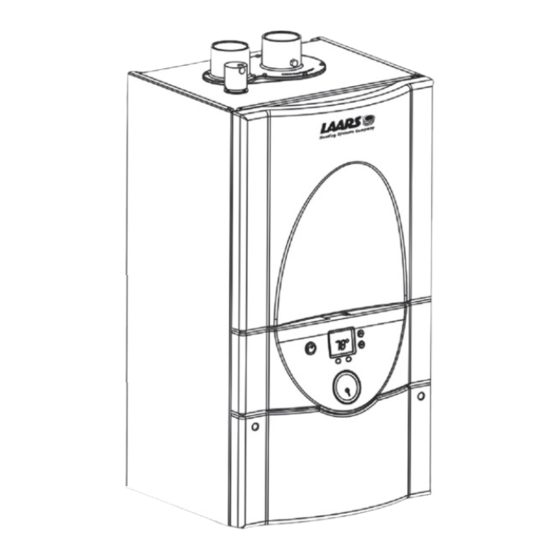
Page 6: Product Overview
LAARS Heating Systems Page 4 1.7 Appliance Overview SHOWN WITH SEVERAL PANELS COMPLETELY REMOVED Figure 1B. Location of Components. 1) PRV, 30 PSI 5) Exhaust terminal assy 2) PRV Pipe w/ washer 6) Air intake terminal assy 3) Wall attach bracket... -
Page 7: Dimensions
Mascot II Boilers and Water Heaters Page 5 1.8 Dimensions Cond. Hydronic Hydronic Outlet Return Inlet Return Supply Supply Outlet Supply 3/4" 3/4" 1/2" 3/4" 1/2" 3/4" 1/2" 3/4" copper copper copper Figure 3. Dimensional Drawing. -
Page 8: Locating The Appliance
LAARS Heating Systems Page 6 SECTION 2. Locating the Appliance 2.1 Locating the Appliance APPLIANCE SUGGESTED SERVICE ACCESS CLEARANCE SURFACE INCHES Mascot II is for indoor, wall-mounted Left Side installations only. Right Side The appliance should be located to provide clearances on all sides for maintenance and inspection. - Page 9 Mascot II Boilers and Water Heaters Page 7 Note: Mascot II bracket and wall bracket are purposely offset. Figure 5. Mounting Detail. Figure 6. Wall Template (not to scale). Full-size template is included with the unit. (Minimum) NOTE: Mascot II models include 16" on-center mounting holes on upper rear of boiler jacket.
-
Page 10: Venting And Combustion Air
When taken from the wall, it must Method 1: Two permanent openings, one be taken from out-of-doors by means of the LAARS commencing within 12" (300mm) of the top and one horizontal wall terminal, shown in Table 3. -
Page 11: Venting (Exhaust)
Mascot II Boilers and Water Heaters Page 9 shall also be supplied for ventilation, including air IN CANADA all venting used must meet the required for comfort and proper working conditions for following requirements: personnel. ULC-S636 certified and marked The first 3 feet of venting must be accessible for visual inspection. -
Page 12: Side Wall Vent Terminal
3.3.1 Side Wall Vent Terminal Vent outlet must be no lower than the center of The appropriate Laars side wall vent terminal must the air inlet, and must be at least 12" (30cm) away be used. The terminal must be located in accordance... - Page 13 Mascot II Boilers and Water Heaters Page 11 U.S. Installations (see note 1) Canadian Installations (see note 2) A= Clearance above grade, veranda, porch, 12 inches (30 cm) 12 inches (30 cm) deck, or balcony See note 6 See note 6 B= Clearance to window or door that may be Direct vent only: 12 inches (30cm);...
-
Page 14: Common Vent Test
LAARS Heating Systems Page 12 Massachusetts thirty (30) day period, a battery operated carbon In Massachusetts the following items are required monoxide detector with an alarm be installed. if the side-wall exhaust vent termination is less than 2. Approved Carbon Monoxide Detectors... - Page 15 Mascot II Boilers and Water Heaters Page 13 Follow the lighting instructions. Adjust thermostat so the appliance will operate continuously. 5. Test for spillage at the draft hood relief opening after 5 minutes of main burner operation. Use the flame of a match or candle, or smoke from a cigarette, cigar or pipe.
-
Page 16: Gas Supply And Piping
LAARS Heating Systems Page 14 SECTION 4. Gas Supply and Piping MASCOT II NATURAL GAS REQUIRED SIZE CU FT / HR. 4.1 Gas Supply and Piping Gas piping should be supported by suitable TO SIZE PIPING: hangers or floor stands, not the appliance. -
Page 17: Pump Capacity
Mascot II Boilers and Water Heaters Page 15 SECTION 5. Pump Capacity Included with 5.1 Mascot II Heating System Mascot II Pump Capacity A Pressure Relief Valve is included with each Mascot II. The PRV must be installed prior to filling the system. when rigid hangers are installed. -
Page 18: Freeze Protection
LAARS Heating Systems Page 16 Figure 13. Hydronic Piping — High and low temp zones with indirect water heater (LMH using internal 3-way). The boiler piping system of a hot water heating which could result in leaking or flooding conditions. -
Page 19: Recognized Chemicals
Setpoint is made via aquastat located on the indirect responsibility. water heater, or can be controlled at the boiler via a remote sensor. Figure 14. Hydronic Piping — Low temp system with indirect water heater (LMH using internal 3-way). - Page 20 16°C 21°C Mascot II application: TEMP RISE °C Honeywell AM100-US-1 Contact Laars for additional recommended models. Table 8. DHW and Pump Performance Data. Installer to provide and install (anti-scald) thermostatic mixing valve. Figure 15. Hydronic Piping — Low temp system.
- Page 21 Mascot II Boilers and Water Heaters Page 19 Figure 16. Hydronic Piping — Multi boilers for large homes with long / multiple baseboard zones.
- Page 22 LAARS Heating Systems Page 20 Figure 17. Hydronic Piping — Multi boilers for large homes with long / multiple radiant zones.
- Page 23 Mascot II Boilers and Water Heaters Page 21 Figure 18. Hydronic Piping — Heating zones piped with zone pumps.
- Page 24 LAARS Heating Systems Page 22 Figure 19. Hydronic Piping — Heating zones piped with zone valves.
-
Page 25: Electrical Connections
Figures 21-22. 7.6 Domestic Hot Water Connection Important Note: DO NOT MAKE/BREAK MASCOT II For LMH and indirect water heater, connect LINE VOLTAGE TO SIGNAL CALL FOR HEAT. A “call aquastat for remote sensor to terminals 7 & 8 (see for heat / end call for heat”... -
Page 26: Wiring Diagrams
LAARS Heating Systems Page 24 If there are more boilers in the system connect a wire from Modbus port 1 terminal A of boiler 2 to Modbus port 1 terminal A of boiler 3. Repeat these steps until all Modbus port 1 terminal A connections are wired. - Page 27 Mascot II Boilers and Water Heaters Page 25 CIRCUIT BREAKER CIRCUIT BREAKER Figure 22. Wiring Diagram.
-
Page 28: Control Setup And Operation
LAARS Heating Systems Page 26 MENU ITEM FUNCTION RANGE DEFAULT SECTION 8. Outlet water Displays the current outlet 55-180°F 120°F Control Setup and Operation temperature water temperature & allows the setpoint to be adjusted Inlet water Displays the current inlet —... -
Page 29: Ignition Control- Sequence Of Events
DHW setpoint is displayed during DHW mode. for established flame. If flame is sensed the control For LMH model, an aquastat will be used in lieu of a enters "Run" to satisfy the demand. If flame is sensor to control temperature of an indirect tank. -
Page 30: Hydronic Heating Demand
LAARS Heating Systems Page 28 SECTION 9. on when the water temperature reaches 115°F. Set the hysteresis values to match the boiler to the system Modes of Operation operating characteristics. Setting this value correctly will help reduce the chance of short cycling. -
Page 31: Hydronic Heating Using Local Lead-Lag/Cascading Feature
It may cycle on and off under very low flow rates. Minimum flow is 0.5 gpm. For LMH, an optional indirect water heater can be piped-in using Mascot's integral 3-way valve as a zone valve. An aquastat in the indirect water heater connected in place of the flow switch will signal demand for DHW. -
Page 32: Set Up Instructions
LAARS Heating Systems Page 30 SECTION 10. system is ready for operation. 12. Refer to local codes and the make-up water valve Set Up Instructions manufacturer’s instructions as to whether the 10.1 Filling the Boiler System make-up water valve should be left open or closed. -
Page 33: Boiler Setup And Adjustment
Mascot II Boilers and Water Heaters Page 31 (see Figure 25). Mascot II will enter the start sequence. Blower Repeat steps 1 and 2 to confirm that the CO and pump will energize for pre-purge, then the ranges are within the required ranges. High and ignition sequence starts. - Page 34 LAARS Heating Systems Page 32 Note: High and Low Fire CO 2 settings should be approximately equal. Manifold Pressure Screw (under cap) High-fire setting Low-fire setting Figure 25. Adjustment Screws and Settings for CO MANIFOLD GAS TYPE (%) RANGE PRESSURE (inH20) 8.8 __ 9.8...
-
Page 35: Maintenance
Section Component Description 11.2.3 Ignitor Assembly Use only genuine LAARS replacement parts. The ignitor assembly is a two rod system that Caution consists of a ground rod and a sense rod. To remove the... -
Page 36: Flame Sensor
LAARS Heating Systems Page 34 11.2.4 Flame Sensor Remove the nuts located on the outside diameter of the burner door to the heat exchanger. The flame sensor is a single rod system. To replace the flame sensor electrode, shut off the 120 Volt power Remove the burner door/burner assembly from the supply to the boiler. -
Page 37: Sequence Of Operation
Mascot II Boilers and Water Heaters Page 35 SECTION 12. manufacturer's instruction supplied with the kit. Trouble Shooting AVERTISSEMENT Ce conversion doit être installé par un organisme de 12.1 Sequence of Operation service conformément aux instructions du fabricant Mascot II is a cold start appliance that should et tous les codes et les exigences de l'autorité... - Page 38 LAARS Heating Systems Page 36 CODE# PROBLEM PROBABLE CAUSE SOLUTION COMMON LOCKOUT CODES Internal error Flame rod to ground Check wiring / probe grounded, dirty probe Flame rod to ground leakage Faulty flame detector Clean or replace flame detector 24VAC voltage low/high Faulty transformer Check/correct supply line voltage;...
- Page 39 Mascot II Boilers and Water Heaters Page 37 CODE# PROBLEM PROBABLE CAUSE SOLUTION ALERT CODES was reached however the cycle count will not increment any higher than 999,999 cycles Replace controller or adjust the count using blue display Maximum hours count Control operates correctly, was reached however the hours count will...
-
Page 40: General Information
Use only genuine LAARS replacement parts. 13.1 General Information To order or purchase parts for the LAARS Mascot II, contact your nearest LAARS dealer or distributor. If they cannot supply you with what you need, contact Customer Service (see back cover for address, telephone and fax numbers). - Page 41 Mascot II Boilers and Water Heaters Page 39 ITEM DESCRIPTION SIZE 125 ITEM DESCRIPTION SIZE 125 BURNER COMPONENTS - see Figure 33 PLUMBING COMPONENTS - see Figure 35 Burner, main R2069102 Tank, expansion, rect, 10 liter A2117400 Gasket, burner RS2108500 Bracket weldment, expansion tank 12H3020 Tile, refractory, front, combustion chamber...
- Page 42 LAARS Heating Systems Page 40 Figure 28. Panel Assembly, Door Top.
- Page 43 Mascot II Boilers and Water Heaters Page 41 Figure 29. Panel Assembly, Door Middle.
- Page 44 LAARS Heating Systems Page 42 Figure 30. Panel Assembly, Door Bottom.
- Page 45 Mascot II Boilers and Water Heaters Page 43 Figure 31. Base Jacket Assembly.
- Page 46 LAARS Heating Systems Page 44 Figure 32. Heat Exchanger Cabinet, Fan.
- Page 47 Mascot II Boilers and Water Heaters Page 45 Figure 33. Heat Exchanger Burner Components.
- Page 48 LAARS Heating Systems Page 46 Figure 34. Pump Assembly Components.
- Page 49 Mascot II Boilers and Water Heaters Page 47 Figure 35. Plumbing Components.
- Page 50 LAARS Heating Systems Page 48...
- Page 51 Mascot II Boilers and Water Heaters Page 49...
- Page 52 (Customer Service, Service Advisors) 20 Industrial Way, Rochester, NH 03867 • 603.335.6300 • Fax 603.335.3355 (Applications Engineering) 1869 Sismet Road, Mississauga, Ontario, Canada L4W 1W8 • 905.238.0100 • Fax 905.366.0130 www.Laars.com Litho in U.S.A. © Laars Heating Systems 1301 Document 1230C...
Need help?
Do you have a question about the LMH and is the answer not in the manual?
Questions and answers