Table of Contents
Advertisement
Installation and Operation Instructions
Installation and Operation
Instructions for
Mighty Therm
Lo-Nox
These instructions are to be stored in the pocket provided on the boiler.
FOR YOUR SAFETY: This product must be installed and serviced by a professional service technician,
qualified in hot water boiler installation and maintenance. Improper installation and/or operation could
create carbon monoxide gas in flue gases which could cause serious injury, property damage, or death.
Improper installation and/or operation will void the warranty.
If the information in this manual is not followed exactly, a fire or explosion may result
causing property damage, personal injury or loss of life.
Do not store or use gasoline or other flammable vapors and liquids in the vicinity of this or
any other appliance.
• Do not try to light any appliance.
• Do not touch any electrical switch; do not use any phone in your building.
• Immediately call your gas supplier from a nearby phone. Follow the gas supplier's
instructions.
• If you cannot reach your gas supplier, call the fire department.
Installation and service must be performed by a qualified installer, service agency, or gas
supplier.
Hydronic Boilers and
Volume Water Heaters
Models PH and PW
Sizes 500-1825
WARNING
WHAT TO DO IF YOU SMELL GAS
Document 2130
Advertisement
Table of Contents
Troubleshooting

Related Manuals for Laars Mighty Therm


Summary of Contents for Laars Mighty Therm
- Page 1 Installation and Operation Instructions Document 2130 Installation and Operation Instructions for Mighty Therm Lo-Nox Hydronic Boilers and Volume Water Heaters Models PH and PW Sizes 500-1825 These instructions are to be stored in the pocket provided on the boiler. FOR YOUR SAFETY: This product must be installed and serviced by a professional service technician, qualified in hot water boiler installation and maintenance.
-
Page 2: Table Of Contents
LAARS HEATING SYSTEMS Page 2 TABLE OF CONTENTS 4.1.6 Flow Switch ..........16 SECTION 1. 4.1.7 Low Water Cut Off ........16 General Information Start-Up Requirements ....... 16 Introduction ........... 3 Normal Operating Sequence ...... 17 Heater Identification ........3 Hi-Limit Checkout ........ -
Page 3: General Information
Experience has shown that orifices, wiring or draft diverter may void the Laars most problems are caused by improper installation, not warranty. If field conditions require such system design. -
Page 4: Installation
LAARS HEATING SYSTEMS Page 4 SECTION 2. Clearance Indoor Outdoor Installation from unobstructed 2.1 Heater Placement Water Conn. side The heater must be placed to provide specific Pump side clearances on all sides for maintenance and Front Alcove* unobstructed inspections. There must also be minimum distances maintained from combustible surfaces. -
Page 5: Forced-Air Ventilation
When the installation of a draft fan is necessary and one at the ceiling, so the total net free area could be in connecting a venting system to a Laars heater, double the figures indicated. For special conditions refer to the the installation should be engineered by latest edition of ANSI Z223.1. -
Page 6: Removal Of Existing Heater
Verify that the heater is fitted for the proper type appropriate Tables in Appendix G in the of gas by checking the rating plate. Laars heaters National Fuel Gas Code, ANSI Z223.1. -
Page 7: Electrical Wiring
The correct burner manifold gas pressure is packet provided with each unit. stamped on the rating plate. The regulator is All Laars heaters need 115V 60Hz supply preset at the factory and normally requires no voltage unless specifically ordered otherwise. -
Page 8: Water Piping Instruction
3.1 General Piping Practice water. Laars recommends primary-secondary pumping Be sure to provide valves at the inlet and outlet for all variable flow systems (see Figure 9). Primary-... -
Page 9: Combined Space Heating/Potable Water Heating Systems
Water Heating Systems Suggested Wiring Diagram For Tempering System Water at When using the Laars boiler as a source of heat Changeover From Heating To Cooling for a combined space heating/potable water heating system, be sure to follow the instructions of the space heating system. -
Page 10: Piping System Requirements
3.3 Water Heater (PW Model) 3.3.1 Water Chemistry 3.2.6 Filling The System Laars equipment is designed for use in a wide Ensure the system is fully connected. Close all variety of water conditions. The water velocity bleeding devices and open make-up water valve. -
Page 11: Piping System Requirements
Mighty Therm Lo-Nox Page 11 3.3.2 Piping System Requirements Check piping diagrams with local applicable plumbing, heating and building safety codes. All two-temperature systems using temperature valves must have forced recirculation in the low temperature building loop. A check valve installed at the hot water inlet to... - Page 12 LAARS HEATING SYSTEMS Page 12 NOTES: Heavy line indicates Heater to Tank Circulating Loop. Figure 12. Hot Water Supply System with Vertical Tank. NOTES: Heavy line indicates Heater to Tank Circulating Loop. Figure 13. Hot Water Supply System with Horizontal Tank.
-
Page 13: Water Pressure
Mighty Therm Lo-Nox Page 13 NOTES: 1. Heavy line indicates Heater to Tank Circulating Loop. 2. When a very large volume of water is circulated in the building loop with the use of a separate pump, tee building loop into cold water supply and return to storage tank. -
Page 14: Tank Installation
LAARS HEATING SYSTEMS Page 14 certified in accordance with the requirements for Be sure the tank is suitable for the water in the Relief Valves and Automatic Gas Shutoff Devices for system. Some water is corrosive and requires a Hot Water Supply Systems, ANSI Z21.22. (in Canada, protected tank with a special lining. -
Page 15: Operating Instructions
Mighty Therm Lo-Nox Page 15 Legend Check Valve Tempering Valve Venturi (Suction) Tee Throttling Valves / Service Valves Figure 16. Two Temperature Hot Water Supply System with Vertical Tank. 4.1.2 Hot Surface Igniter WARNING This is a 120 VAC, silicon carbide igniter. -
Page 16: Flow Switch
LAARS HEATING SYSTEMS Page 16 NOTE: Indoor unit shown. Outdoor unit, door must be removed to access controls. Figure 17. Controls Location. Figure 18. Operating and Safety Components. shut down whenever overheating of water occurs 4.2 Start-Up Requirements (exceeding the temperature set point of the switch). -
Page 17: Normal Operating Sequence
Mighty Therm Lo-Nox Page 17 NOTE: Safe lighting and other performance The ignition control turns on the combustion criteria were met with the gas manifold and control blower. After about a 15 second pre-ignition assembly provided on the heater when it underwent purge, while the blower clears the combustion tests specified in ANSI Z21.13 and CAN1-4.3-M85. -
Page 18: Lighting Instructions
LAARS HEATING SYSTEMS Page 18 Do not use this appliance if any part has been For boilers with the temperature controller bulb under water. Immediately call a qualified service at the boiler inlet, set the high-limit 40°F to 50°F technician to inspect the appliance and to replace above temperature controller setting. -
Page 19: Combustion Air Blower
Mighty Therm Lo-Nox Page 19 If a strainer is used in a pressure reducing valve or in the piping, clean it every 6 months in accordance with the manufacturer's instructions. At startup and every 6 months after, using the burners view port, look at the burner flame for proper performance. -
Page 20: Internal Cleaning Of Heat Exchanger
Remove the return cover of the heat exchanger. understand the sequence of operation of the heater: Clean the internal surface. (Laars offers a tube Upon a call for heat a 24 VAC signal is sent cleaning kit part no. R00100000.) through fusible links and high limit(s) to the Reassemble in the reverse order. -
Page 21: Electrical Components
Mighty Therm Lo-Nox Page 21 After the call for heat is satisfied the ignition Make sure none of the manual reset controls, i.e., control closes the gas valves and operates the low water cutoff, high limit, etc., have tripped. blower for a thirty (30) second post purge cycle. - Page 22 LAARS HEATING SYSTEMS Page 22 Figure 21. Troubleshooting Chart.
-
Page 23: Mechanical Components
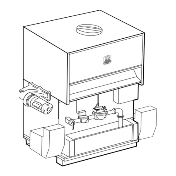
Mighty Therm Lo-Nox Page 23 6.3 Mechanical Components 6.3.1 Pressure Relief Valves Leaking Intermittently or Steadily Possible Cause Remedy Static pressure in system exceeds Calculate height of water in system above heater. Install setting of relief valve. new valve with psi setting 25% above required static system working pressure. - Page 24 LAARS HEATING SYSTEMS Page 24 Figure 22. Parts Identification.
-
Page 25: Parts Descriptions And Order Numbers
Mighty Therm Lo-Nox Page 25 SECTION 7. Parts Descriptions and Order Numbers Key Description Size Size Size Size Size 1010 1430 1825 Jacket and Combustion Chamber Components Top Panel Assembly (Indoor) 10535701 10535703 10535705 10535707 10535709 Spacer, Flue Collector 10540800... -
Page 26: Electrical Components
LAARS HEATING SYSTEMS Page 26 Key Description Size Size Size Size Size 1010 1430 1825 Baffle Heat Exchanger Front/Rear 20020101 20020103 20020105 20020107 20020109 Baffle, Heat Exchanger (10-Tube) 10667701 10667703 10667705 10667707 10667709 (18) (18) (36) (18) Baffle, Heat Exchanger (10-Tube) - Page 27 Mighty Therm Lo-Nox Page 27 When ordering tiles: Assembly number is for all tiles. Part numbers shown for the front of unit are the same for the rear tiles. Check dimensions of old tile as shown here to confirm part number.
- Page 28 LAARS HEATING SYSTEMS Page 28 Description Size Size Size Size Size 1010 1430 1825 Base, Lower Section 10602001 10602003 10602005 10602007 10602009 Base, Upper Section 10602101 10602103 10602105 10602107 10602109 Tile Rail, Left Support 10955000 10955000 10955000 10955000 10955000 Tile Rail, Right Support...
- Page 29 Mighty Therm Lo-Nox Page 29 Description Size Size Size Size Size 1010 1430 1825 Ignition Control, Electronic E2101300 E2101300 E2101300 E2101300 E2101300 Transformer, 115V/24V E0086100 E0086100 E0086100 E0086100 E0086100 Switch, High Limit, Manual Reset E0015900 E0015900 E0015900 E0015900 E0015900 Controller, Water Temp (2-stage)
- Page 30 LAARS HEATING SYSTEMS Page 30 500 / 715 On / Off or 2-Stage 1010, 1430, 1825 On / Off only 1010, 1430, 1825 2-Stage only Description Size Size Size Size Size 1010 1430 1825 Valve, Gas, Combination, Dual V0077200 V0077200 —...
- Page 31 Mighty Therm Lo-Nox Page 31 Description Size Size Size Size Size 1010 1430 1825 Housing, Inlet Air, Blower 10953500 10953500 10953500 10953500 10953500 Orifice, Air (Dual) 10953902 10953903 10953905 10953907 10953909 Orifice, Air (Single) 10953901 10953901 — — — Housing, Blower, Right...
- Page 32 LAARS HEATING SYSTEMS Page 32 Description Size Size Size Size Size 1010 1430 1825 Air Duct 10953000 10953000 10953000 10953000 10953000 Gasket, Cover 30-268 30-268 30-268 30-268 30-268 Cover, Air Mixture, Plenum 10956401 10956403 10956405 10956407 10956409 Divider, Air Mixture, Front...
-
Page 33: Outdoor Jacket
Mighty Therm Lo-Nox Page 33 Key Description Size Size Size Size Size 1010 1430 1825 Outdoor Jacket Top Panel 10660701 10660703 10660705 10660707 10660709 Rear Windshield 10658101 10658103 10658105 10658107 10658109 Upper Rear Louver Shield 10657101 10657103 10657105 10657107 10657109... - Page 34 LAARS HEATING SYSTEMS Page 34 Key Description Size Size Size Size Size 1010 1430 1825 Lower Rear Shield -Inner 10659901 10659903 10659905 10659907 10659909 Rear Base Extension 10658501 10658503 10658505 10658507 10658509 Left Front End Panel 10936300 10936300 10936300 10936300...
- Page 35 Mighty Therm Lo-Nox Page 35...
- Page 36 6000 Condor Drive, Moorpark, CA 93021 • 805.529.2000 • FAX 805.529.5934 20 Industrial Way, Rochester, NH 03867 • 603.335.6300 • FAX 603.335.3355 480 S. Service Road West, Oakville, Ontario, Canada L6K 2H4 • 905.844.8233 • FAX 905.844.2635 www.laars.com Litho in U.S.A. © Laars Heating Systems 0008 Document 2130...
Need help?
Do you have a question about the Mighty Therm and is the answer not in the manual?
Questions and answers