Laars NTH Installation And Operation Instructions Manual
Modulating boilers
Hide thumbs
Also See for NTH:
- Installation and operation instructions manual (92 pages) ,
- User manual (16 pages)
Table of Contents
Advertisement
Quick Links
Installation and Operation Instructions
FOR YOUR SAFETY: This product must be installed and serviced by a professional service technician,
qualified in hot water boiler and heater installation and maintenance. Improper installation and/or operation
could create carbon monoxide gas in flue gases which could cause serious injury, property damage, or
death. Improper installation and/or operation will void the warranty.
If the information in this manual is not
followed exactly, a fire or explosion may
result causing property damage, personal
injury or loss of life.
Do not store or use gasoline or other
flammable vapors and liquids in the vicinity
of this or any other appliance.
WHAT TO DO IF YOU SMELL GAS
• Do not try to light any appliance.
• Do not touch any electrical switch; do not
use any phone in your building.
• Immediately call your gas supplier from a
nearby phone. Follow the gas supplier's
instructions.
• If you cannot reach your gas supplier, call
the fire department.
Installation and service must be performed
by a qualified installer, service agency, or gas
supplier.
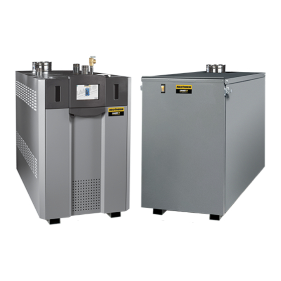
Outdoor
Indoor
WARNING
Installation and Operation
Instructions for
with Touchscreen Display
Modulating Boiler
Model NTH
Sizes 150–850 MBTU/h
Water Heater
Model NTV
Sizes 150–850 MBTU/h
AVERTISSEMENT
Assurez-vous de bien suivres les instructions
données dans cette notice pour réduire au
minimum le risque d'incendie ou d'explosion
ou pour éviter tout dommage matériel, toute
blessure ou la mort.
Ne pas entreposer ni utiliser d'essence ni
d'autres vapeurs ou liquides inflammables dans
le voisinage de cet appareil ou de tout autre
appareil.
QUE FAIRE SI VOUS SENTEZ UNE ODEUR DE GAZ:
• Ne pas tenter d'allumer d'appareils.
• Ne touchez à aucun interrupteur. Ne pas vous
servir des téléphones dansle bâtiment où vous
vous trouvez.
• Appelez immédiatement votre fournisseur de
gaz depuis un voisin. Suivez les instructions
du fournisseur.
• Si vous ne pouvez rejoindre le fournisseur de
gaz, appelez le sservice des incendies.
L'installation et l'entretien doivent être assurés par
un installateur ou un service d'entretien qualifié ou
par le fournisseur de gaz.
Document 1330B
®
Advertisement
Table of Contents
Troubleshooting

Related Manuals for Laars NTH


Summary of Contents for Laars NTH
- Page 1 Installation and Operation Instructions Document 1330B Installation and Operation Instructions for ® with Touchscreen Display Modulating Boiler Model NTH Sizes 150–850 MBTU/h Water Heater Model NTV Outdoor Sizes 150–850 MBTU/h Indoor FOR YOUR SAFETY: This product must be installed and serviced by a professional service technician, qualified in hot water boiler and heater installation and maintenance.
-
Page 2: Table Of Contents
LAARS Heating Systems Table of Contents Section 1 - Section 6A - General Information Water Connections - NTH Boiler 6A.1 NTH System Piping: Hot Supply Introduction ............1 Connections ............ 24 1.2 Model Identification ........... 1 6A.2 NTH Cold Water Make-Up ......24 1.3 Appliance Overview ........2-7 6A.3 Condensate Drain ........... - Page 3 NeoTherm Boilers and Water Heaters, 150 to 850 MBTU/h Section 8 - Section 9 - Navigating the Touch Screen First Start Up and Adjustment 8.1 The Touch Screen ........41 9.1 Filling the Boiler System ......... 60 8.2 Using the Touch Screen ........ 41 9.2 First Operation ..........60 8.3 Verification Process for Safety-Related 9.3...
- Page 4 LAARS Heating Systems...
-
Page 5: General Information
1) The National LAARS Heating Systems warranty will be voided. The Electrical Code ANSI/NFPA No. 70-latest Edition, or 2) installation must conform to the requirements of the CSA STD. -
Page 6: Appliance Overview
1.3 Appliance Overview The only component (interior) difference between the Indoor The LAARS NeoTherm is offered in both Indoor and and Outdoor models is that all of the piping for the Outdoor Outdoor models for all sizes. The physical appearance of the... - Page 7 Page 3 Boilers and Water Heaters HERM CONNECTION EXHAUST WATER OUTLET VENT AIR INLET WATER INLET Indoor 210 MBH CONDENSATE DRAIN Figure 2. Connection piping is on TOP for ALL Indoor Sizes EXHAUST VENT AIR INLET FILTER BOX WATER OUTLET Outdoor 210 MBH WATER INLET CONDENSATE TRAP GAS VALVE PRV must be added to this pipe during installation.
- Page 8 Page 4 LAARS Heating Systems EXHAUST VENT CONNECTION PRESSURE RELIEF VALVE GAS CONNECTION WATER INLET WATER OUTLET AIR INLET CONNECTION TOUCHSCREEN AIR PRESSURE SWITCH ON / OFF SWITCH DRAIN VALVE HEAT EXCHANGER GAS VALVE AIR TRANSITION CONDENSATE TRAP AIR/ GAS...
- Page 9 Page 5 Boilers and Water Heaters HERM EXHAUST VENT CONNECTION WATER INLET PRESSURE RELIEF VALVE WATER OUTLET GAS CONNECTION AIR INLET CONNECTION TOUCHSCREEN ON / OFF SWITCH HEAT EXCHANGER MANUAL SHUTOFF DRAIN VALVE GAS VALVE CONDENSATE TRAP AIR/ GAS BLOWER GAS VALVE VENTURI Figure 6.
- Page 10 Page 6 LAARS Heating Systems EXHAUST VENT CONNECTION WATER INLET GAS CONNECTION WATER OUTLET PRESSURE RELIEF VALVE AIR INLET CONNECTION TOUCHSCREEN AIR PRESSURE SWITCH ON / OFF SWITCH DRAIN VALVE MANUAL SHUTOFF GAS VALVE CONDENSATE TRAP HEAT EXCHANGER AIR/ GAS BLOWER...
- Page 11 Page 7 Boilers and Water Heaters HERM GAS CONNECTION AIR INLET WATER OUTLET WATER INLET EXHAUST VENT Indoor 850 MBH CONDENSATE DRAIN Figure 10. Connection piping is on TOP for ALL Indoor Sizes EXHAUST VENT CONNECTION WATER OUTLET WATER INLET AIR INLET FILTER BOX Outdoor 850 MBH CONDENSATE DRAIN PRV must be added to this pipe during installation.
-
Page 12: Dimensions, Indoor Models
Page 8 LAARS Heating Systems 1.4 Dimensions, Indoor Models Size/Model 150 NTV 13¼ 34 5¼ 14 19 48 3¼ 8 10¾ 28 7½ 19 14¼ 36 19½ 49 7½ 19 15¼ 39 13 33 199 NTV 20½ 52 5¼ 14 19 48 3¼... - Page 13 Page 9 Boilers and Water Heaters HERM (22) (98) (64) (19)
-
Page 14: Dimensions, Outdoor Models
Page 10 LAARS Heating Systems 1.5 Dimensions, Outdoor Models SIZE 6-1/4" 16 11" 13" 17-1/4" 43.8 23-1/2" 60 18" 45.7 27" 23-1/2" 60 199 / 210 6-1/4" 16 11" 13" 17-1/4" 43.8 23-1/2" 60 18" 45.7 27" 24-1/2" 60 6" 15.5 11"... - Page 15 Page 11 Boilers and Water Heaters HERM Ø L (length) VENT SIZE 8" 45.7 27" 23-1/2" 60 6-1/4" 16 5-1/4" 13 11" 13" 17-1/4" 43.8 23-1/2" 60 18" 45.7 27" 23-1/2 8" 45.7 27" 199 / 210 24-1/2" 60 6-1/4" 16 5-1/4"...
-
Page 16: Warranty
(See Figure 12) warranty registration at www.Laars.com. All warranty claims must be made at www.Laars.com. or to an A. Exhaust vent terminal (US only) authorized LAARS Heating Systems representative. Claims B. Air intake terminal... -
Page 17: Locating The Appliance
Page 13 Boilers and Water Heaters HERM Section 2 - NOTE: When located on the same wall, the NeoTherm LOCATING THE APPLIANCE combustion air intake terminal must be installed a minimum of 12” below the exhaust terminal. Models 399-850 also require a minimum horizontal 2.1 General Information distance from intake to exhaust terminal of 36”. -
Page 18: Venting And Combustion Air
The manufacturers and product lines listed on the following tables have been tested and authorized Installations must comply with applicable national, state and to safely operate with Laars equipment. Suppliers of stainless local codes. steel and polypropylene venting that are not listed on these tables are not permitted for use with Laars vent category III/ IV products. - Page 19 Page 15 Boilers and Water Heaters HERM Combustion Air From Room of all equipment in the enclosure. When communicating to the outdoors through horizontal ducts, each opening shall In the United States, the most common requirements specify have a minimum free area of not less than 1 square inch per that the space shall communicate with the outdoors in 2000 Btu/hr (1100 square mm/kW) of total input rating of all accordance with method 1 or 2, which follow.
-
Page 20: Venting
When taken from the wall, it must be taken from complies with UL 1738 Standard. (See Table 6) out-of-doors by means of the LAARS horizontal wall terminal, kit, See Table 7. The unit’s vent can terminate through the roof, or through an outside wall. - Page 21 However, if one is not available with NeoTherm boilers and water heaters are Vent Category IV the certified vent system, Laars suggests using a tee with the appliances. Per the requirements of CAN/CSA-B149.1, only branch connection sized to allow for insertion of a flue gas BH vent systems can be connected to these units and such analyzer probe.
-
Page 22: Locating Vent & Combustion Air Terminals
Side Wall Vent Terminal upon local conditions. The appropriate Laars side wall vent terminal must be used. If the NeoTherm is side-wall vented to the same wall, The terminal must be located in accordance with ANSI locate the vent terminal at least 1 foot (0.3m) above the... - Page 23 Page 19 Boilers and Water Heaters HERM U.S. Installations (see note 1) Canadian Installations (see note 2) A= Clearance above grade, veranda, porch, 12 inches (30 cm) 12 inches (30 cm) deck, or balcony See note 6 See note 6 B= Clearance to window or door that may be Direct vent only: 12 inches (30cm);...
- Page 24 Page 20 LAARS Heating Systems When combustion air is taken from the roof, a field-supplied that during said thirty (30) day period, a battery operated rain cap or an elbow arrangement must be used to prevent carbon monoxide detector with an alarm be installed.
-
Page 25: Common Vent Test
Page 21 Boilers and Water Heaters HERM 3.5 Common Vent Test REMARQUE : Lorsqu’une chaudière existante est NOTE: This section does not describe a method for supprimée d’un système de ventilation commun, le système common venting NeoTherm units. It describes what must be done when a unit is removed from a common de ventilation commun est susceptible d’être trop grande vent system. -
Page 26: Gas Supply And Piping
Page 22 LAARS Heating Systems Section 4 - NEOTHERM NATURAL GAS GAS SUPPLY AND PIPING REQUIRED CU FT SIZE / HR. TO SIZE PIPING: Gas piping should be supported by suitable hangers or floor Measure linear distance from meter outlet to last boiler. -
Page 27: Pump Requirements
Page 23 Boilers and Water Heaters HERM Section 5 - PUMP REQUIREMENTS 5.1 NeoTherm Boiler Flow and Head Requirements - NTH TEMPERATURE RISE IN °F 20°F 25°F 30°F 35°F 40°F FLOW H/L FLOW H/L FLOW H/L FLOW H/L FLOW H/L SIZE 150 14.3 28.5 11.4 19... -
Page 28: Section 6A
Section 6B covers NTV models, which without a pump included. are designed exclusively for “volume water” NeoTherm NTH models 80-500 can also be ordered with or domestic hot water applications. Refer to the without a pump included. proper section for instructions on installing NeoTherm MUST be piped in a primary-secondary fashion and piping your product. -
Page 29: Condensate Drain
Connect a 3/4” PVC pipe between the drain connection and temperature rise through the boiler. a floor drain (or a condensate pump if a floor drain is not NOTE: Laars supplied pumps are not all capable of accessible). maintaining the reduced temperature rise required The condensate drain must be installed so as to prevent with glycol concentrations greater than 35%. - Page 30 Page 26 LAARS Heating Systems Figure 21. Hydronic Piping — Single Boiler, Zoning with Circulators...
- Page 31 Page 27 Boilers and Water Heaters HERM Figure 22. H ydronic Piping — Single Boiler, Low Temp Radiant Space Heating Using Low Loss Header and Zone Valves...
- Page 32 Page 28 LAARS Heating Systems Figure 23. Hydronic Piping — Multiple Boilers, Zoning with Circulators...
- Page 33 Page 29 Boilers and Water Heaters HERM Figure 24. Hydronic Piping — Multiple Boilers with Indirect DHW Tank Piped from System Loop...
- Page 34 Page 30 LAARS Heating Systems Figure 25. Hydronic Piping — Multiple Boilers, Reverse Return, Multi-Temp Zones, Zoning with Circulators...
- Page 35 Page 31 Boilers and Water Heaters HERM Figure 26. Hydronic Piping — Heating Zones with Indirect DHW Tank Piped with Zone Pumps The indirect DHW tank is piped directly off of the boiler. The boiler pump must shut down during DHW operation.
- Page 36 Page 32 LAARS Heating Systems Figure 27. Hydronic Piping, Multiple Boilers with Indirect DHW Off of One Boiler The boiler pump must shut down during DHW operation.
-
Page 37: Section 6B
If the water in use exceeds the conditions Section 6 is divided into two parts. Section recommended, a water softener or other device should be 6A covers NTH units designed for hydronic installed to improve water quality. heating. Section 6B covers NTV models, which are designed exclusively for “volume water”... -
Page 38: Cold Water Make-Up
Page 34 LAARS Heating Systems factory pumps or other pumps are installed, the piping should be installed such that the pump supplies flow to the heater it 6B.5 Freeze Protection is attached to only. The factory pumps are sized for 30 feet... - Page 39 Page 35 Boilers and Water Heaters HERM NOTES: 1. Optional CWMU & Recirc. line location. 2. Locate NTV DHW sensor or remote aquastat well in lower 1/3 of tank. 3. Back flow preventer may be required - check local codes. 4.
- Page 40 Page 36 LAARS Heating Systems NOTES: 1. Optional CWMU & Recirc. line location. 2. Locate NTV DHW sensor or remote aquastat well in lower 1/3 of tank. 3. Back flow preventer may be required - check local codes. 4. Thermal expansion tank may be required - check local codes.
-
Page 41: Installation Warnings
(This can also be 0-10Vdc using a converter - Laars part number CA006100.) When setting up The NeoTherm unit does not recognize 4mA as a call a system using an external control, take care to set Anti-Short for heat. - Page 42 Page 38 LAARS Heating Systems Figure 32. Control Panel Layout WATER HEATER SIZES VOLTS PHASE AMPS BOILER PUMP CONNECTIONS 199-500 Single RATINGS No pump SIZES VOLTS PHASE AMPS (Boiler, System Pump and DHW Pump Connections) Single With pump 199–850 Single 115V – Maximum 1HP No Pump or 7.4A max...
-
Page 43: Optional Field Connection
Modbus ports. The Modbus wiring should be completed according to the diagrams shown below. If alternate communication protocols are desired, Laars offers “gateways” to allow BACnet, LON, and other communications protocols. For additional information on setting up Modbus and other communication protocols, contact the factory. - Page 44 Page 40 LAARS Heating Systems R/BLK DKB/Y DKB/Y TRANSFORMER 110VAC INPUT 24VAC OUTPUT GY/WH Figure 36. Wiring Diagram, All Sizes...
-
Page 45: Navigating The Touch Screen
Page 41 Boilers and Water Heaters HERM Section 8 Navigating the Touch Screen The home screen shows a picture of the NeoTherm controller. The color of the controller depends on the status of the NeoTherm, as shown below. Color Status Control Touch Screen Icon Blue Normal operation... - Page 46 Page 42 LAARS Heating Systems (For some special safety-related functions, besides Screen Menu Icons entering the correct password, the system will ask you to go through an additional “verification” process. For more information, see the section on “Configuration.”) When a password is necessary, the system will present the keyboard screen.
-
Page 47: Verification Process For Safety-Related Parameters
Page 43 Boilers and Water Heaters HERM to login before you make a change. (For more Each time you press a key, the system will respond with a beep. If you are entering a password, an information on logging in, see Section 8.2.) asterisk (*) will appear for each character you enter. - Page 48 Page 44 LAARS Heating Systems 8.4 Checking Individual Parameters From the ‘Home’ screen (Menu 9), press the icon for the controller. Menu 7. Safety Parameter Confirmation For each group, check the list carefully. Press Yes if all of the parameters in the group have Menu 9.
-
Page 49: Configuring Parameters On Individual
Page 45 Boilers and Water Heaters HERM 8.5 Configuring Parameters In this section, we will give you a quick explanation of how to change parameters on the controller. From the Home Page screen (Menu 11), press the icon for the controller. Menu 11. Home Page Screen The Status Summary page for that controller Menu 13. -
Page 50: Setting The Date And Time
Page 46 LAARS Heating Systems 8.6 Setting the Date and Time on the System Display The display includes an internal clock, which keeps track of the date and time. This setting is important, because log entries for Lockouts and Alerts include time listings. If the Date and Time setting for the boiler is not correct, the listings in the Lockout and Alert logs will be incorrect. -
Page 51: Configuration Menus (All)
Page 47 Boilers and Water Heaters HERM 8.7 Configuration Sub-Menus (ALL) 8.7.1 through 8.7.15 are the Configuration Sub-Menus. 8.7.1 System Identification & Access Menu 18. Home Screen To navigate to the Configuration Menu Screen, first touch the controller icon on the home screen to access the Status This sub-menu will display information regarding software, Summary screen, date codes, model numbers and program name, as well as giving the installer access to re-name the boiler and to change... -
Page 52: Dhw - Domestic Hot Water Configuration
NeoTherm is designed with a 5:1 turn down ratio. Any temperature parameters for water heaters (NTV) and for indirect water heaters that are used with boiler (NTH) systems. change to the minimum and maximum modulation rates will affect the overall ratio of the boiler. The installer level password will allow changes to these parameters. -
Page 53: Statistics Configuration
Page 49 Boilers and Water Heaters HERM 8.7.8 Pump Connections (cont) 8.7.10 High Limits The System pump connections are located on terminal block 5 (TB5) in the control panel. The System pump contacts are rated for 120Vac, 7.4 Amps. To use the contacts, power must be supplied on one terminal with the other terminal wired to the pump or a relay controlling the pump. -
Page 54: Frost Protection Configuration
Page 50 LAARS Heating Systems 8.7.13 Frost Protection 8.7.15 Fan Configuration To increase/decrease the speed at which the fan control loop reacts to a decrease in fan speed, adjust the Fan gain down parameter. Similarly, to increase/decrease the speed at which the fan control loop reacts to an increase in fan speed, adjust the Fan gain up parameter. -
Page 55: About Lead / Lag
Page 51 Boilers and Water Heaters HERM About Lead/Lag Operation Caution About Lead/Lag Operation - You should set the Modbus addresses before If an installation includes two or more boilers, they you connect the Modbus wiring. If the wiring may be set up for “Lead/Lag” operation. One boiler is attached before the Modbus addresses on will be set up as the “Leader”, and the others will the controls are changed, there will be multiple... - Page 56 Page 52 LAARS Heating Systems Base load value Number of boilers installed Low demand - The first boiler in sequence fires at less than 65% Demand increases - Once the first boiler reaches 65%, the second boiler Figure 43. Base Load Settings...
-
Page 57: Lead Lag Follower Configuration
Page 53 Boilers and Water Heaters HERM 8.7.17 Lead/Lag Follower Configuration Menu 21. Home Screen On the boilers, touch the controller Icon on the Home Screen. Menu 23. Configuration Menu, Scroll down and select ‘Lead Lag Slave Configuration’. Menu 22. Status Summary Screen Select ‘Configure’. In the Lead Lage Follower Sub-Menu, Identify each unit (including the Lead/Lag Leader) as a Follower by turning on “Follower Enable.”... -
Page 58: Lead Lag Leader Configuration
Page 54 LAARS Heating Systems 8.7.18 Lead Lag Leader Configuration You will be prompted to sign in. This can be done by pressing the ‘LOCK’ symbol at the top right Then set up the Leader controller by going to the Lead Lag Leader boiler and opening up the Lead Lag Leader Configuration in that boilers Configuration Menu. -
Page 59: Connections To A Building Automation System
Modbus ports. The Modbus Controller wiring must be completed according to the diagrams shown below. If alternate communication protocols are desired, LAARS offers “gateways” to allow BACnet, Operator LON, and other communications protocols. For interface MB1 MB2... -
Page 60: Combustion Setup
Page 56 LAARS Heating Systems 8.10.1 – Combustion Setup Procedure In this section, we will explain how to set up the gas valve so the boiler will run efficiently at both the High Fire and Low Fire conditions. Required tools: Screwdrivers, Torx bits, Allen... - Page 61 Page 57 Boilers and Water Heaters HERM Auto at the end of the test. Manual in Run - The Manual in Run control will only set the fan speed when the control has proven flame and the unit has entered the Run mode. Manual in Run and Standby - Using this setting, the manual control will set the fan speed whether the boiler is operating or not.
-
Page 62: Adjusting Co2
Page 58 LAARS Heating Systems 8.10.2 – Adjusting CO See Section 8.10 GAS TYPE HIGH FIRE, CO LOW FIRE, CO DIFFRNTL PRESSURE (inches wc) Natural 8.8 to 9.8% 0.5% lower than 3.6” to 3.9” high fire setting Propane 9.8 to 10.2% Table 17. (Residential, sizes 150 - 285 Mbtu) Range and Differential Pressure... - Page 63 Page 59 Boilers and Water Heaters HERM Table 19. NeoTherm Boiler Efficiencies Inlet gas pressure High re CO adjustment (under cap) pressure Low re CO adjustment Outlet gas pressure Inlet gas Low re CO pressure adjustment High re CO adjustment (under cap) 750, 850 Outlet Gas Outlet Pressure...
-
Page 64: First Start Up And Adjustment
LAARS Heating Systems Section 9 - Prime the condensate trap with water. (This is not First Start Up and Adjustment required for NTH 600, 750, and 850 units.) Refer to local codes and the make-up water valve 9.1 Filling the Boiler System manufacturer’s instructions as to whether the make-up water valve should be left open or closed. -
Page 65: Shutting Down The Neotherm Unit
Page 61 Boilers and Water Heaters HERM 9.3 Shutting Down the NeoTherm Unit label and turn on the gas and electrical power to the appliance. Turn off the main electrical disconnect switch. Turn the NeoTherm on. Close all manual gas valves. The NeoTherm unit will begin the start sequence. If you think the NeoTherm unit might freeze, drain it. -
Page 66: Maintenance
On Outdoor models only as needed per air quality, remove and inspect the air filter. Clean with soapy water Use only genuine LAARS replacement parts. if needed. Be sure that filter is dry before re-inserting The gas and electric controls in the unit are engineered back into air filter box. - Page 67 Page 63 Boilers and Water Heaters HERM and cleaning. connectors. To remove the control, push in on the two tabs on the left side of the board to unlatch the clips from the control Reassemble the valve/Venturi assembly in reverse order, making sure to include all gaskets and O-rings.
- Page 68 Page 64 LAARS Heating Systems 3/16”). Replace the gasket if necessary. Heat Exchanger Coils Black carbon soot buildup on the heat exchanger is caused by one or more of the following; incomplete combustion, Flame Sensor combustion air problems, venting problems, or heater short The flame sensor is a single rod system.
-
Page 69: Battery Back Up For Date And Time
The touchscreen does have an internal battery for back-up gas valve adjustment. Other units require no additional parts - only proper gas valve adjustment. Please contact the Laars of the date and time settings. To access the battery, the front... -
Page 70: Troubleshooting
Page 66 LAARS Heating Systems Section 11 TROUBLESHOOTING Lockout will appear in an orange bar across the bottom of the screen. If you tap the orange bar, 11.1 Lockouts, Holds, and Alerts the system will present more information about The control system on the NeoTherm responds to the Lockout. - Page 71 Page 67 Boilers and Water Heaters HERM If you choose ‘LOCKOUTS’, this menu will appear. 3. Press the long Yellow Alert or Yellow Lockout Bar (the long bar will be a long Grey ‘History’ Bar if not currently in Alert or Lockout). Menu 5.
-
Page 72: Troubleshooting Table
Page 68 LAARS Heating Systems 11.2 Troubleshooting Table This table includes a listing of the fault codes that may be displayed. Some of these can be corrected by changing a parameter, while other conditions are more complicated, and will require a service technician. - Page 73 Page 69 Boilers and Water Heaters HERM Code Description Lockout Procedure or Hold Internal fault: Safety relay test failed due to safety relay OFF Internal fault: Safety relay test failed due to safety Internal fault relay not OFF 1. Reset module Internal fault: 2.
- Page 74 Page 70 LAARS Heating Systems Code Description Lockout Procedure or Hold Modulation fault Internal sub-system fault. 1. Review alert messages for possible trends. 2. Correct possible problems. Pump fault Internal sub-system fault. 1. Review alert messages for possible trends. 2. Correct possible problems.
- Page 75 Page 71 Boilers and Water Heaters HERM Code Description Lockout Procedure or Hold Outlet high limit H or L 1. Check wiring and correct any possible errors. 2. Replace the outlet high limit. 3. If previous steps are correct and fault persists, replace the module.
- Page 76 Page 72 LAARS Heating Systems Code Description Lockout Procedure or Hold Pressure Sensor Fault 1. Verify the Pressure Sensor is a 4-20 ma source. 2. Check wiring and correct any possible errors. 3. Test Pressure Sensor for correct operation. 4. Replace the Pressure sensor.
- Page 77 Page 73 Boilers and Water Heaters HERM Code Description Lockout Procedure or Hold Flame not detected Sequence returns to standby and restarts sequence at the beginning of Purge after the HF switch opens if fl ame detected during Safe Start check up to Flame Establishing period.
- Page 78 Page 74 LAARS Heating Systems Code Description Lockout Procedure or Hold Invalid BLOWER / SPARK output setting Invalid Delta T limit enable setting Invalid Delta T limit response setting L 1. Return to Confi guration mode and recheck Invalid DHW (Domestic Hot Water) selected parameters, reverify and reset module.
- Page 79 Page 75 Boilers and Water Heaters HERM Code Description Lockout Procedure or Hold Unconfi gured DHW (Domestic Hot Water) high limit setpoint setting Unconfi gured Outlet high limit setpoint setting 1. Return to Confi guration mode and recheck Unconfi gured Stack limit setpoint selected parameters, reverify and reset module.
-
Page 80: Diagnostic Tests And Input/Output Indicators
Page 76 LAARS Heating Systems 11.3 Diagnostic Tests and Input/ Output Indicators Two kinds of screens are grouped together in this section: • Detailed indications of the input and output signals • Diagnostic tests of the pumps and burner modulation Note that these functions apply to just one selected controller. -
Page 81: Lead/Lag Slave Diagnostics
Page 77 Boilers and Water Heaters HERM 11.4 Lead/Lag Slave Diagnostics The control system includes a diagnostic screen that lists some information on the Lead/Lag slaves in the system. See Menu 13 Menu 15. Analysis Setup Screen To use this function, select the parameter you want to track from the pull-down list. -
Page 82: Operating Sequence
Page 78 LAARS Heating Systems 11.8 Operating Sequence Select one of the controllers listed on the right side When there is a call for heat, the unit will close of the screen. Press one of the buttons below the pump contacts to energize the customer supplied relay/contactor to start water fl... -
Page 83: Replacement Parts
12.1 General Information To order or purchase parts for the LAARS NeoTherm, contact your nearest LAARS dealer or distributor. If they cannot supply you with what you need, contact Customer Service. (See the back cover for the address, telephone and fax numbers.) 12.2 Parts List... - Page 84 RV2019300 RV2019300 — 59 Blower Gasket W/Fasteners — — — — — RS2107500 RS2107500 RS2107500 Heat Exchanger Components – See Parts Illustration 7 60 Heat Exchanger, NTH RS2105800 RS2105700 RS2111100 RS2111200 RS2111300 RS2111300 RS2111400 RS2111500 Heat Exchanger, NTV S2111000 61 Pump Assembly R10D4110 R20D4140...
-
Page 85: Parts Illustrations
Page 81 Boilers and Water Heaters HERM SIZE SIZE SIZE SIZE SIZE SIZE SIZE SIZE ITEM DESCRIPTION NTH 150 NTH 210 NTH 285 NTH 399 NTH 500 NTH 600 NTH 750 NTH 850 NTV 150 NTV 199 NTV 285 NTV 399... - Page 86 Page 82 LAARS Heating Systems Parts Illustration 1. Jacket Components...
- Page 87 Page 83 Boilers and Water Heaters HERM Parts Illustration 2. I nternal Components, Parts Illustration 3. I nternal Components, Sizes 150–210 Sizes 285–600...
- Page 88 Page 84 LAARS Heating Systems Parts Illustration 4. Internal Components, Sizes 750-850...
- Page 89 Page 85 Boilers and Water Heaters HERM Sizes 150-285 Parts Illustration 5. Gas Train Components, Sizes 150-500...
- Page 90 Page 86 LAARS Heating Systems Parts Illustration 6. Gas Train Components, Sizes 600-850...
- Page 91 Page 87 Boilers and Water Heaters HERM Sizes 285 - Parts Illustration 7. Heat Exchanger Components...
-
Page 92: Parts Illustrations
Page 88 LAARS Heating Systems (Front) Touchscreen (Back) Battery ( CR2032 ) Parts Illustration 8. Electrical Components... - Page 93 Page 89 Boilers and Water Heaters HERM Notes:...
- Page 94 Page 90 LAARS Heating Systems Notes:...
- Page 95 Page 91 Boilers and Water Heaters HERM Notes:...
- Page 96 Dimensions and specifications subject to change without notice in accordance with our policy of continuous product improvement. 800.900.9276 • Fax 800.559.1583 Customer Service and Product Support: Industrial Way, Rochester, NH, USA 03867 • 603.335.6300 • Fax 603.335.3355 Headquarters: 1869 Sismet Road, Mississauga, Ontario, Canada L4W 1W8 • 905.238.0100 • Fax 905.366.0130 www.Laars.com Printed in U.S.A. © Laars Heating Systems 1604 Document 1330B...
Need help?
Do you have a question about the NTH and is the answer not in the manual?
Questions and answers