Advertisement
Installation, Operation and Maintenance Instructions
Installation,
Operation and
Maintenance
Instructions for
Newport
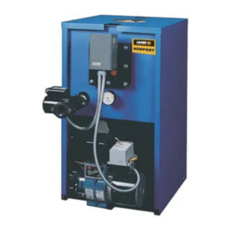
Oil Fired Boiler
FOR YOUR SAFETY: This product must be installed and serviced by a professional service technician,
qualified in boiler installation and maintenance. Improper installation and/or operation could create
carbon monoxide gas in flue gases which could cause serious injury, property damage, or death.
Improper installation and/or operation will void the warranty.
If the information in this manual is not followed exactly, a fire or explosion may result
causing property damage, personal injury or loss of life.
Do not store or use gasoline or other flammable vapors and liquids in the vicinity of this or
any other appliance.
Installation and service must be performed by a qualified installer, service agency, or fuel oil
supplier.
WARNING
A subsidiary of BRADFORD WHITE Corporation
Document 1100B
Advertisement
Table of Contents

Subscribe to Our Youtube Channel
Related Manuals for Laars newport NP 75


Summary of Contents for Laars newport NP 75
- Page 1 Installation, Operation and Maintenance Instructions Document 1100B Installation, Operation and Maintenance Instructions for Newport Oil Fired Boiler FOR YOUR SAFETY: This product must be installed and serviced by a professional service technician, qualified in boiler installation and maintenance. Improper installation and/or operation could create carbon monoxide gas in flue gases which could cause serious injury, property damage, or death.
- Page 2 LAARS HEATING SYSTEMS Page 2 TABLE OF CONTENTS SECTION 1. Oil Storage and Pipe Layout ......3 Electrical Wiring ..........4 General Information Operation Boiler Installation .......... 3 (Honeywell L.8124A aquastat relay) ..... 4 Freight Claims ..........3 Domestic Water Piping ......... 4 Boiler Location ..........
-
Page 3: General Information
Trianco Newport Page 3 SECTION 1. 1F. Combustion and Ventilation Air To insure an adequate supply of fresh air for General Information combustion and ventilation an inlet and outlet opening should be provided at floor and ceiling level. Each These boilers have been designed and opening must have a minimum of one square inch constructed according to ASME codes using heavy (16.5 sq. -
Page 4: Operation
LAARS HEATING SYSTEMS Page 4 storage level is not below the fuel unit. A two pipe Connect gate or shutoff valve (13) to anti scald system of not less than 3/8" OD copper tubing is tempering valve (12) “MIX” port, and another to recommended when lowest fuel level is below but not the cold water inlet. - Page 5 Trianco Newport Page 5 PRESSURE RELIEF VALVE AIR VENT DRAIN (PIPE IN ACCORDANCE SUPPLY PIPE WITH EXISTING REGULA- TIONS) AQUASTAT RELAY L8124A ¾" NPT TANKLESS DOMES- HOT WATER COIL WIRING CONDUIT ½" NPT TRIDICATOR CIRCULATOR 1¼" NPT FLAME VIEWING PORT BURNER Tapping Tankless Coil...
-
Page 6: Servicing The Burner
LAARS HEATING SYSTEMS Page 6 1R. Servicing the Burner 1T. Coil Removal This should only be carried out by a trained and Switch off electrical supply and turn off water to licensed service technician in accordance with the boiler. burner maker’s instructions. - Page 7 Trianco Newport Page 7 Dimensions NP 75 NP 85 NP 100 NP 110 NP 125 NP 135 NP 150 inches inches inches inches inches inches inches Jacket Height 35½ 35½ 35½ 1041 1041 1041 Jacket Width 19¼ 19¼ 19¼ 19¼ 20½...
- Page 8 LAARS HEATING SYSTEMS Page 8 Instructions 1. Pre-assemble L/H side (1) and R/H side (2) to front panel (3) with screws. 2. Slide assembled jacket over boiler and secure side panels to base tray. 3. Fix rear panel (4) to sides.
-
Page 9: One-Pipe System
Trianco Newport Page 9 Air vent 1¼" min. Fill pipe One-Pipe System Oil tank Valve "P" Burner Boiler Filter "H" Figure 5A Two-Pipe Air vent 1¼" min. Burner System Filter Boiler Fill pipe Valve "H" tank Figure 5B PIPE LENGTHS PIPE LENGTHS One Pipe Gravity System Two Pipe Gravity System... - Page 10 LAARS HEATING SYSTEMS Page 10 Power supply provides disconnect means & overload protection as required. Room Thermostat L1 (Hot) Power Supply 120V Circulator Switch Low Limit Circulator Hi Limit Oil Burner Relay Heating Circulator AQUASTAT RELAY L8124A WIRING ARRANGEMENT FOR “NP” BOILER CONTROLLING OPERATION OF BOILER AND CIRCULATOR Figure 6.
-
Page 11: Part Numbers
Trianco Newport Page 11 SECTION 2. Part Numbers Part Number Description Size Part Number Description Size 51-002 Boiler Body ........85/115 53-090 Flue Cover Assembly ....125/155 51-056 Base Assembly (after 1990 - ..85/115 53-108 Front Panel Assembly ....125/155 includes 51-058 panel) ......
Need help?
Do you have a question about the newport NP 75 and is the answer not in the manual?
Questions and answers