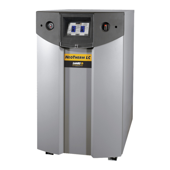
Laars NTH1000 Installation And Operation Instructions Manual

Laars NTH1000 Installation And Operation Instructions Manual

Modulating boiler/water heater
Hide thumbs Also See for NTH1000:
Table of Contents

Advertisement

Installation and Operation Instructions
FOR YOUR SAFETY: This product must be installed and serviced by a professional service technician,
qualified in hot water boiler and heater installation and maintenance. Improper installation and/or operation
could create carbon monoxide gas in flue gases which could cause serious injury, property damage, or
death. Improper installation and/or operation will void the warranty.
If the information in this manual is not
followed exactly, a fire or explosion may
result causing property damage, personal
injury or loss of life.
Do not store or use gasoline or other
flammable vapors and liquids in the vicinity
of this or any other appliance.
WHAT TO DO IF YOU SMELL GAS
• Do not try to light any appliance.
• Do not touch any electrical switch; do not
use any phone in your building.
• Immediately call your gas supplier from a
nearby phone. Follow the gas supplier's
instructions.
• If you cannot reach your gas supplier, call
the fire department.
Installation and service must be performed
by a qualified installer, service agency, or gas
supplier.
Installation and
Operation Instructions for
N
Modulating Boiler
Model NTH1000
1,000 MBTU/h
Model NTH1700
1,700 MBTU/h
WARNING
T
EO
HERM
Assurez-vous de bien suivres les instructions
données dans cette notice pour réduire au
minimum le risque d'incendie ou d'explosion ou
pour éviter tout dommage matériel, toute blessure
ou la mort.
Ne pas entreposer ni utiliser d'essence ni d'autres
vapeurs ou liquides inflammables dans le
voisinage de cet appareil ou de tout autre appareil.
QUE FAIRE SI VOUS SENTEZ UNE ODEUR DE GAZ:
• Ne pas tenter d'allumer d'appareils.
• Ne touchez à aucun interrupteur. Ne pas vous
servir des téléphones dansle bâtiment où vous
vous trouvez.
• Appelez immédiatement votre fournisseur de
gaz depuis un voisin. Suivez les instructions du
fournisseur.
• Si vous ne pouvez rejoindre le fournisseur de
gaz, appelez le sservice des incendies.
L'installation et l'entretien doivent être assurés par
un installateur ou un service d'entretien qualifié ou
par le fournisseur de gaz.
Document 1255B
LC
®
Water Heater
Model NTV1000
1,000 MBTU/h
Model NTV1700
1,700 MBTU/h
AVERTISSEMENT

Advertisement

Table of Contents
loading
Need help?

Need help?

Do you have a question about the NTH1000 and is the answer not in the manual?

Questions and answers

Subscribe to Our Youtube Channel

Summary of Contents for Laars NTH1000

  • Page 1 Installation and Operation Instructions Document 1255B Installation and Operation Instructions for HERM ® Modulating Boiler Water Heater Model NTH1000 Model NTV1000 1,000 MBTU/h 1,000 MBTU/h Model NTH1700 Model NTV1700 1,700 MBTU/h 1,700 MBTU/h FOR YOUR SAFETY: This product must be installed and serviced by a professional service technician, qualified in hot water boiler and heater installation and maintenance.
  • Page 2: Table Of Contents

    NeoTherm LC Boilers and Water Heaters Table of Contents Section 1 Section 6 General InformatIon ........1 Water connectIonS ........20 Introduction ..........1 about the touch Screen ......1 Section 6a - nth Systems ........20 Safety notes ..........3 6A.1 NTH System Piping: Hot Supply connections ..........
  • Page 3 LAARS Heating Systems Section 9 – 10.2.1 Initial burner operation ......89 SetUp anD confIGUratIon ......44 10.2.2 Combustion Setup Procedure ....89 9.1 Review of Lead/Lag Control System ..44 10.3 Shutting Down the NeoTherm LC ... 89 9.1.1 About Lead/Lag Operation ..... 44 10.4 Restarting the NeoTherm LC ....89 9.1.2 Lead/Lag Modulation Cycle ....45 9.1.3 NTH Lead/Lag with Indirect...
  • Page 4 LAARS Heating Systems...
  • Page 5: General Information

    If you have any questions regarding this equipment, of the reason why the NeoTherm LC 1000 or 1700 can deliver such outstanding performance. You please consult the LAARS Heating Systems factory, can access the control system using the ‘Touch or a local factory representative. Many operating Screen Display’...
  • Page 6 Page 2 LAARS Heating Systems • Each controller and burner work together. Each By changing this one value, you change the boiler includes two of these controller/burner setpoint used by the whole system. The action combinations. of all of the controller/burner pairs will refer back to that single value.
  • Page 7: Safety Notes

    NeoTherm LC Boilers and Water Heaters Page 3 manual includes two longer sections that will help requirements take precedence over the general you to work with the control system: instructions contained herein. • Section 8 – “Using the Touch Screen and the Gauges.”...
  • Page 8: Warranty

    Warranty claim must also include the installation date and name of the installer. Shipping costs are not included LAARS Heating Systems’ NeoTherm LC appliances in the warranty coverage. are covered by a limited warranty. The owner should Some accessory items may be shipped in separate complete the warranty registration at: packages.
  • Page 9 NeoTherm Boilers and Water Heaters Page 5 The Touchscreen does have an internal battery for back-up of the date and time settings. To access the battery, the front panel and the Touchscreen must be removed so that the small plastic door on the back of the touchscreen can be accessed.
  • Page 10: Dimensions

    Page 6 LAARS Heating Systems Fig. 5 - Dimensions - NT 1000 DANGER Dimensions • Water temperature over 125°F (52°C) can cause The dimensions are shown in Fig. 5 and severe burns instantly or death from scalds. Fig. 6. • Children, disabled and elderly are at highest risk of being scalded.
  • Page 11 NeoTherm LC Boilers and Water Heaters Page 7 Fig. 6 - Dimensions - NT 1700...
  • Page 12: Locating The Appliance

    Page 8 LAARS Heating Systems Section 2 LOCATING THE APPLIANCE APPLIANCE SUGGESTED SERVICE ACCESS CLEARANCE SURFACE INCHES Front 60.9 Locating the Appliance Left Side 30.5 The NeoTherm LC may be installed indoors or outdoors. The unit may only be installed outdoors Right Side 45.7...
  • Page 13: Venting And Combustion Air

    NeoTherm LC Boilers and Water Heaters Page 9 Section 3 VENTING AND COMBUSTION AIR Combustion Air shall be of the same cross-sectional area as the free NeoTherm LC boilers and water heaters must area of the openings to which they connect. have provisions for combustion and ventilation air in accordance with the applicable requirements Method 1: Two permanent openings, one...
  • Page 14: Ducted Combustion Air

    The combustion air can be taken through the wall, or through the roof. When taken from the wall, it must be taken from out-of-doors by means of the LAARS horizontal wall terminal, shown in Table 3a. See Table 2 to select the appropriate diameter air pipe.
  • Page 15: Venting

    Failure to use the appropriate vent material, supplier’s recommended installation techniques. installation techniques, or glues and sealants could If these are not available, refer to the Laars lead to vent failure causing property damage, recommendations for the material used. personal injury or death.
  • Page 16: Locating The Vent And Combustion Air Terminals

    In Canada, the installation must be certified vent system is preferred. However, if one in accordance with CSA B149.1 or .2 and local is not available with the certified vent system, Laars applicable codes. suggests using a tee with the branch connection...
  • Page 17 NeoTherm LC Boilers and Water Heaters Page 13 U.S. Installations (see note 1) Canadian Installations (see note 2) A= Clearance above grade, veranda, porch, 12 inches (30 cm) 12 inches (30 cm) deck, or balcony See note 6 See note 6 B= Clearance to window or door that may be Direct vent only: 12 inches (30 cm);...
  • Page 18: Side Wall Combustion Air Terminal

    The LAARS side wall combustion air terminal must be used when the heater takes air from a side wall. (See Table 3.) Contact Laars for AL29-4C termination fittings. Consider the following when installing the terminal. (See Figures 10 and 11).
  • Page 19: Vertical Vent Terminal

    NeoTherm LC Boilers and Water Heaters Page 15 3.3.3 Vertical Vent Terminal of installation, the owner shall have a period of thirty (30) days to comply with the above re- When the unit is vented through the roof, the vent quirements, provided, however, that during said must extend at least 3 feet (0.9 m) above the point thirty (30) day period, a battery operated carbon...
  • Page 20: Outdoor Installation

    Page 16 LAARS Heating Systems Condensate Drain Trap 3. As much as possible, close all building doors A condensate drain trap is included with the and windows. Also close all doors between NeoTherm LC and is designed to drain the boiler of the space in which the appliances remaining condensate.
  • Page 21: Gas Supply And Piping

    NeoTherm LC Boilers and Water Heaters Page 17 Section 4 GAS SUPPLY AND PIPING Gas Supply and Piping Gas piping should be supported by suitable hangers WARNING or floor stands, not the appliance. Open flame can cause gas to ignite and result in Installers should refer to local building and safety property damage, severe injury, or loss of life.
  • Page 22: Distance & Pipe Size, Tables

    Page 18 LAARS Heating Systems NeoTherm LC SCH 40 METAL PIPE CAPACITY FOR 0.60 SPECIFIC GRAVITY TO SIZE PIPING: NATURAL GAS NATURAL GAS Measure linear distance from meter outlet to last boiler. Add total input of all boilers REQUIRED NOMINAL PIPE SIZE @ 0.30” W.C. PRESSURE DROP...
  • Page 23: Pump Requirements

    NeoTherm LC Boilers and Water Heaters Page 19 Section 5 PUMP REQUIREMENTS NeoTherm LC Boiler Flow and Head Requirements Temperature Rise in °F 20°F 25°F 30°F 35°F 40°F 45°F Model Flow H/L-Ft Flow H/L-Ft Flow H/L-Ft Flow H/L- Flow H/L- Flow H/L-Ft 1,000...
  • Page 24: Water Connections

    Page 20 LAARS Heating Systems Section 6 - WATER CONNECTIONS Suggested piping diagrams are shown in Figures Section 6 is divided into TWO parts. 12 through 16. These diagrams are meant only as Section 6A covers NTH units designed guides. Components required by local codes must be for hydronic heating.
  • Page 25: Nth Freeze Protection

    Do not use automotive antifreeze. To help prevent slope downward toward the drain with no spiraling. freezing, Laars recommends the use of inhibited Consult local codes for the disposal method. glycol concentrations between 20% and 35% glycol.
  • Page 26 Page 22 LAARS Heating Systems Low temp. radiant zone Space heating zone circuits Space heating zone circuit System pump Air vent 4 pipe dia. max. 4 pipe dia. max. 4 pipe dia. max. Water feed controls 4 pipe dia. max.
  • Page 27 NeoTherm LC Boilers and Water Heaters Page 23 Air vent 4 pipe dia. max. Water feed Anti-scald controls mixing valve 4 pipe Domestic dia. max. hot water Expansion tank Indirect DHW tank Note - This drawing is a schematic representation of a piping style, and is not intended to be used as a working installation drawing.
  • Page 28 Page 24 LAARS Heating Systems Note - This drawing is a schematic representation of a piping style, and is not intended to be used as a working installation drawing. Local code requirements must be met. Low temp. radiant zone Low temp. radiant zone...
  • Page 29 NeoTherm LC Boilers and Water Heaters Page 25 Space heating Note - zone circuits This drawing is a schematic representation of a piping style, and is not intended to be used as a working installation drawing. Local code requirements must be met. Low temp.
  • Page 30 Page 26 LAARS Heating Systems Space heating zone circuits High temp. space heating zone circuit Space heating zone circuit Air vent 4 pipe dia. max. 4 pipe dia. max. Water feed controls Expansion tank 4 pipe dia. max. Common piping must be sized for the combined water flow of all the boilers.
  • Page 31: Section 6B - Ntv Systems

    NeoTherm LC Boilers and Water Heaters Page 27 Section 6B - NTV Systems 6B.1 NTV Water Quality 6B.2 NTV Piping Requirements NTV water heaters must be installed in water The water piping should be supported by suitable conditions of 10 gpg hardness or less, with a pH hangers and floor stands.
  • Page 32: Ntv Cold Water Make-Up

    Page 28 LAARS Heating Systems 6B.3 NTV Cold Water Make-Up 6B.5 NTV Suggested Piping Schematics The cold water make-up may be connected to the tank or to the inlet of the boiler as shown in Figures Figures 17-19 show suggested piping 17-19.
  • Page 33: Ntv Suggested Pumps

    NeoTherm LC Boilers and Water Heaters Page 29 Building return NOTES: WARNING: This drawing shows 1. Optional CWMU & recirculation suggested piping configuration and line location. valving. Check with local codes and 2. Locate the NTV DHW sensor ordinances for additional requirements. Cold water or remote aquastat well supply...
  • Page 34: Electrical Connections

    Page 30 LAARS Heating Systems Section 7 ELECTRICAL CONNECTIONS WARNING The NeoTherm LC appliance must be electrically Caution grounded in accordance with the requirements of The supply voltage to the NeoTherm LC must not the authority having jurisdiction or, in the absence...
  • Page 35 NeoTherm LC Boilers and Water Heaters Page 31 TB10 Primary controller Secondary controller (upper burner) (lower burner) Fig. 20 - Electronics Panel Layout...
  • Page 36: Vac Transformer With Integral Circuit Breaker

    Page 32 LAARS Heating Systems Signal Connections Model 1,000 1,700 See Section 9 for details on the following Voltage 120 V AC 120 V AC connections: Current - FLA 12 A 30 A • System sensor Current - Nominal 16 A •...
  • Page 37: Ladder Diagrams

    NeoTherm LC Boilers and Water Heaters Page 33 Fig. 21 - Ladder Diagram...
  • Page 38 Page 34 LAARS Heating Systems Fig. 22 - Wiring Diagram...
  • Page 39 NeoTherm LC Boilers and Water Heaters Page 35...
  • Page 40: Using The Touch Screen And Gauges

    Page 36 LAARS Heating Systems Section 8 In multiple boiler configurations, each NeoTherm LC will still have it’s own Touch Screen, but only USING THE TOUCH SCREEN AND the Touch Screen on the lead boiler will be active. GAUGES Up to 8 controllers (4 boilers) can be displayed on the ‘home’...
  • Page 41 NeoTherm LC Boilers and Water Heaters Page 37 Login Home Upper Return to Home page left-hand corner Bell Upper System in Lockout, left-hand Reset required corner Shift Backspace Padlock Upper Shows whether a Clear Cancel right-hand password has been corner entered so parameters Fig.
  • Page 42: While Operating - Checking Lead/Lag Operating Information

    Page 38 LAARS Heating Systems At the bottom of the screen shown in Fig. 28, the Blue Normal operation system is telling you that it wants you to log in. Gray and Communication crossed out problem Yellow Hold state. This...
  • Page 43: While Operating - Checking Individual Parameters

    NeoTherm LC Boilers and Water Heaters Page 39 You can change the setpoints from this condition of that controller, and also shows screen. When you press the yellow box beside some of the configuration settings. See Fig. 34. Setpoint, the controller presents this screen: Fig.
  • Page 44: Checking Individual Details

    Page 40 LAARS Heating Systems Checking Individual Details 8.7 Configuring Parameters on Individual Controllers The Details button on the Status Summary screen leads to a series of screens that show all of the setup In this section, we will just give you a quick parameters entered for the controller you have selected.
  • Page 45: Verification Process For Safety-Related Parameters

    NeoTherm LC Boilers and Water Heaters Page 41 Press the Configure button to start a configuration session for the selected controller. See Fig. 39. Fig. 41 - Numeric Entry Screen 8.8 Verification Process for Safety- Related Parameters Fig. 39 - Configuration Screen When you start to change a parameter that is related to safety, the system will present a This screen lists all of the configuration warning which looks like this:...
  • Page 46 Page 42 LAARS Heating Systems When you are done entering parameters, the next job is to do the verification. Login to the system and press Begin. Fig. 43 - Verification Needed Notes – • Once you change one of these safety-related Fig. 45 - Edit Safety Data...
  • Page 47 NeoTherm LC Boilers and Water Heaters Page 43 Fig. 47 - Safety Parameter Reset The Reset button is located on the front of the controller. See Fig. 44. You must press the Reset button within 30 seconds, or the verification will be cancelled.
  • Page 48: Setup And Configuration

    Page 44 LAARS Heating Systems Section 9 SETUP AND CONFIGURATION Review of Lead/Lag Control System 9.1.1 About Lead/Lag Operation The boilers in this series are always set up for Lead/ On a multiple-boiler installation, each individual Lag operation. In a single-boiler installation, there boiler is still set up as shown in Fig.
  • Page 49: Lead/Lag Modulation Cycle

    NeoTherm LC Boilers and Water Heaters Page 45 In either kind of installation, a system sensor is Let’s consider the following example: usually used to monitor the demand. The input from Four NeoTherm LC boilers are tied together via this sensor is used to control the modulation rates of Modbus connections.
  • Page 50: Nth Lead/Lag With Indirect Domestic Hot Water

    Page 46 LAARS Heating Systems 9.1.3 NTH Lead/Lag with Indirect Boiler X Boiler Y Domestic Hot Water So far, we have been describing a system which Low demand - handles the Central Heat function only. There are The first burner* in...
  • Page 51 NeoTherm LC Boilers and Water Heaters Page 47 Fig. 51 – Connection Terminals...
  • Page 52 Page 48 LAARS Heating Systems Table 12 – Installations for Special Options System Multiple System Common Setpoint Modulation Outdoor or single or local vent control control, 4-20 reset boilers boiler 4-20 ma control Single Local boiler Single Local boiler Multiple...
  • Page 53 NeoTherm LC Boilers and Water Heaters Page 49 Table 12 – Installations for Special Options (continued) Single System boiler Single System Yes, from boiler system Multiple System boiler Multiple System Yes, from boiler system Multiple System boiler Multiple System Yes, from boiler system Multiple...
  • Page 54 Page 50 LAARS Heating Systems System 4 – Multiple boilers, Local control, Outdoor reset Job B Set up the names for each of the controllers Job C Make one control the Lead/Lag master Job D On each of the controllers that will act as a slave, disable the Lead/Lag Master...
  • Page 55 NeoTherm LC Boilers and Water Heaters Page 51 System 7 – Single boiler, System control Job I Set the parameters used by the Lead/Lag system Job L Building automation or multiple boiler control thermostat demand Job O Set up the combustion on each of the burners Job P Set the date and time on the system System 8 –...
  • Page 56 Page 52 LAARS Heating Systems System 11 – Single boiler, System control, 4-20 mA setpoint control Job I Set the parameters used by the Lead/Lag system Job M Building automation or multiple boiler control 4-20 mA setpoint control Job O...
  • Page 57 NeoTherm LC Boilers and Water Heaters Page 53 System 15 – Single boiler, System control, 4-20 mA modulation control Job N Building automation or multiple boiler control 4-20 mA modulation control Job O Set up the combustion on each of the burners Job P Set the date and time on the system System 16 –...
  • Page 58 Page 54 LAARS Heating Systems System 20 – Multiple boiler, System control, Common vent, 4-20 mA setpoint control, Outdoor reset Job A Note on common venting Job B Set up the names for each of the controllers Job C Make one control the Lead/Lag master...
  • Page 59: Installation Jobs

    NeoTherm LC Boilers and Water Heaters Page 55 Installation Jobs Note – To install your system, you will not need to do all of the installation jobs listed here. Please refer to Section 9.3 for a list of specific installation jobs necessary to install your system.
  • Page 60: Master

    Page 56 LAARS Heating Systems present the keyboard screen. Use the “BS” (BackSpace) key to erase the existing name. Enter the new name, then press OK. Now you can rename the other control on Boiler 1 – the Secondary control. Press the Home button in the top left-hand corner to go back to the ‘home’...
  • Page 61: D Disable The Lead/Lag Master Function On The Lead/Lag Slaves

    Master (usually the Primary controller for Boiler 1) also serves as a Slave (usually Slave 1). A single controller performs both functions. When the controllers arrive from the Laars factory, Fig. 61 – Configuration Screen they will all be configured as slaves. Your job in this...
  • Page 62: Set Up The Modbus Control Addressing

    Page 58 LAARS Heating Systems Job E – Set Up the Modbus Control Press the Control Setup button. Figure 65 shows the Control Setup screen. Addressing (This is an individual function – do this for each of the controls Use the separate Touch Screen on each boiler.) Do this on any system with multiple boilers.
  • Page 63: Set The Flap Valve Ids

    NeoTherm LC Boilers and Water Heaters Page 59 Job F - Set the Flap Valve IDs Primary Control on Boiler 1 is “1.” If this is not already set to “1”, enter the correct (These are individual functions. Make the flap valve assignment number, then press OK.
  • Page 64 Page 60 LAARS Heating Systems WARNING If the flap valve identifications are not configured correctly, this could cause the equipment to malfunction. This could lead to personal injury or death, and could damage the equipment. If the configuration is not correct, the control system will present an error –...
  • Page 65 NeoTherm LC Boilers and Water Heaters Page 61 In this example, we are still working with the Table 14 – Number of Controls Primary control for Boiler 1. From the table, Number of Number of you can see that this control should have a flap boilers controls valve ID of “1.”...
  • Page 66 Page 62 LAARS Heating Systems Fig. 76 – Safety Parameter Confirmation Check the list carefully. Press Yes if all of Fig. 74 – Reset Button on Controller the parameters in the group have been entered correctly. The control system allows 30 seconds to press 12. The system will tell you to reset the control the reset button.
  • Page 67: G Disconnect Unused Operator Interfaces

    NeoTherm LC Boilers and Water Heaters Page 63 Job G – Disconnect Unused Touch Screens Fig. 79. Use 22 AWG or thicker shielded twisted pair wire with drain. Two twisted pairs or three Once a Lead/Lag system is set up and operating, the conductors are needed.
  • Page 68: Lead/Lag System

    Page 64 LAARS Heating Systems Boiler 1 (Lead/Lag Master) Boiler 2 Secondary Primary TB9, pin 7 connect to TB9, pin 1 TB9, pin 8 connect to TB9, pin 2 TB9, pin 9 connect to TB9, pin 3 TB9, pin 10...
  • Page 69 NeoTherm LC Boilers and Water Heaters Page 65 DHW time of day setpoint - the System sensor reaches the LL CH Setpoint minus an additional “hysteresis” Separate Time-of-Day Setpoint for Domestic value. Hot Water (See the material on “About the ‘Time of Day’...
  • Page 70 Page 66 LAARS Heating Systems 20 mA water temperature - If a 4 – 20 mA input is used to adjust the Press the left-arrow or right-arrow until you setpoint, this entry sets the high limit of the see the Outdoor Reset screen (Fig. 86).
  • Page 71 NeoTherm LC Boilers and Water Heaters Page 67 Low water temp. - When enabled, the Warm Weather Shutdown feature will turn off the Central Heating If the outdoor temperature reaches the Max. functions when the outdoor temperature Outdoor Temp. or higher, the system will exceeds the setpoint.
  • Page 72: About The "Time Of Day" Function

    Page 68 LAARS Heating Systems Job J - Install the System Sensor and Table 16 – Base Load Settings Adjust the Setpoint Number Base load min. of boilers (This is a Lead/Lag function – do this once for the whole Lead/ Installed Lag system.
  • Page 73: About Outdoor Reset

    NeoTherm LC Boilers and Water Heaters Page 69 Set the outdoor reset and warm weather Setpoint - shutdown parameters as desired. If the outdoor temperature is higher than this, the system will shut off the Lead/Lag How to get there – Outdoor Reset Screen and Warm Central Heating functions.
  • Page 74: L Building Automation Or Multiple Boiler Control Thermostat Demand

    70°F or above, the system will use 100°F (the Low Water Temp.) as the setpoint. Line 2 = CH Setpoint Note - Laars offers “gateways” to allow connections Min. outdoor temp. - to BACnet, LON, and other communications If the outdoor temperature reaches this value protocols.
  • Page 75: N Building Automation Or Multiple Boiler 4-20Ma Modulation Control

    Building Automation System or Multiple boiler control. Enable the Central Heat function on the top Note - Laars offers “gateways” to allow connections line. Give the CH function the priority using to BACnet, LON, and other communications the lower line.
  • Page 76 Page 72 LAARS Heating Systems Boiler 1 Operator Primary Primary interface controller burner valve valve Secondary Secondary controller burner Fig. 97 – Primary and Secondary Burners in a Boiler High fire adjustment Low fire adjustment High fire adjustment Low fire adjustment Fig.
  • Page 77 NeoTherm LC Boilers and Water Heaters Page 73 Press the Operation button. The system will Required tools: Screwdrivers, Torx bits, combustion present the Operation screen for the Secondary analyzer burner. In the rest of this section we will explain the setup procedure in more detail.
  • Page 78 Page 74 LAARS Heating Systems You can change the fan speed of the burner by adjusting the value entered for Firing Rate on the right side of the display. (Remember, a moment ago you selected the Primary control for this boiler, so this change will only affect the Primary burner.) Press the yellow box...
  • Page 79 NeoTherm LC Boilers and Water Heaters Page 75 turn the High Fire adjustment screw counter- • On the Operation screen for the Secondary clockwise. To lower the high fire CO level, burner, press the yellow box for the Firing turn the screw clockwise. Rate.
  • Page 80: System Display

    Page 76 LAARS Heating Systems • Turn off the call for heat, and set both Here is the procedure: burners to run at 1200 RPM for low fire. Turn Start at the ‘home’ screen. on the call for heat, and check the performance again.
  • Page 81: Setup For Domestic Hot Water On A Lead/Lag System

    NeoTherm LC Boilers and Water Heaters Page 77 Select Date and Time. Figure 107 shows the The setup for this is all done from within the Lead/ setup screen. Lag system. You will need to set up an LL CH setpoint and a separate LL DHW setpoint, and assign the priority to the DHW demand.
  • Page 82: Setup Type 2

    Page 78 LAARS Heating Systems is pumped by the DHW pump, and the boiler pump is turned off. This will keep the temperature zones separate. • Each of the boilers that will handle DHW is wired with an input from the aquastat used to indicate DHW demand.
  • Page 83: Setup Type 3

    NeoTherm LC Boilers and Water Heaters Page 79 Select that line by pressing it. If you want to change the DHW priority, the system will ask you to log in using the installer-level password. For this kind of installation, the entry should be “DHW>...
  • Page 84: Gateway Connections To A Building Automation System

    If alternate button to go to the Setup screen. Press the Display communication protocols are desired, Laars offers Setup button to go to the Display Setup screen. On “gateways” to allow BACnet, LON, and other the Display Setup screen, press the COM2 tab to communications protocols.
  • Page 85: Installer Parameters

    NeoTherm LC Boilers and Water Heaters Page 81 Installer Parameters This is a list of all of the parameters which can be accessed using the Installer password. Label Description How to Reach 4 mA water If a 4 – 20 mA input is used to adjust the <’home’...
  • Page 86 Page 82 LAARS Heating Systems Label Description How to Reach CH (Central This controls whether a local Central Heat If Lead/Lag enabled – Heat) has demand has priority over the control asserted by <’home’ screen> Lead/Lag Master button priority over the LL Master, when this controller is enabled as <Lead/Lag Master screen>...
  • Page 87 NeoTherm LC Boilers and Water Heaters Page 83 Label Description How to Reach CH (Central This setpoint is used when the time-of-day input If Lead/Lag enabled – Heat) is off. If the outdoor reset function is active, this <’home’ screen> Lead/Lag Master button Setpoint setpoint provides one coordinate for the outdoor <Lead/Lag Master screen>...
  • Page 88 Page 84 LAARS Heating Systems Label Description How to Reach The DHW pump (Pump C) can be turned <’home’ screen> Select a controller (Domestic on manually, or it can be set to operate <Status Summary screen> Configure Hot Water) automatically. If it is turned on then it remains button <Configuration Menu>...
  • Page 89 NeoTherm LC Boilers and Water Heaters Page 85 Label Description How to Reach Lead lag D This is part of the damping function <’home’ screen> Lead/Lag Master button gain (“Derivative”) used when the controller <Lead/Lag Master screen> Configure interprets the input from the System sensor. button <Lead/Lag Master Configuration screen>...
  • Page 90 Page 86 LAARS Heating Systems Label Description How to Reach Lead lag on When the Lead/Lag function is enabled, the If Lead/Lag enabled – hysteresis control system will not fire the boilers until the <’home’ screen> Lead/Lag Master button temperature at the System sensor drops to the <Lead/Lag Master screen>...
  • Page 91 NeoTherm LC Boilers and Water Heaters Page 87 Label Description How to Reach Modbus Each controller must have a unique Modbus <’home’ screen> Setup button <Setup address address. screen> Control setup button/ Change address button Number of Each controller needs to know how many flap <’home’...
  • Page 92: Initial Startup Instructions

    Page 88 LAARS Heating Systems Section 10 INITIAL STARTUP INSTRUCTIONS 10.1 Filling the Boiler System Ensure the system is fully connected. Close all 11. Shut down the entire system and vent all bleeding devices and open the make-up water radiation units and high points in the system valve.
  • Page 93: Initial Operation

    NeoTherm LC Boilers and Water Heaters Page 89 10.2 Initial Operation Caution The initial setup must be checked before the unit is If any odor of gas is detected, or if the gas burner put into operation. Problems such as failure to start, does not appear to be functioning in a normal rough ignition, strong exhaust odors, etc.
  • Page 94: Maintenance

    11.1 System Maintenance 11.2 Maintenance Notes Do the following once a year: Use only genuine LAARS replacement parts. Lubricate the System pump, if required, per the instructions on the pump. Caution Inspect the venting system for obstruction or When servicing the controls, label all wires before leakage.
  • Page 95: Controllers

    NeoTherm LC Boilers and Water Heaters Page 91 power supply to the boiler. Turn off all manual gas gasket. If the old assembly is determined to be valves connecting the boiler to the main gas supply defective, install a new ignitor assembly in the line.
  • Page 96: Blower

    Page 92 LAARS Heating Systems 11.2.7 Blower Attach a longer hose to the drain and run it to a bucket. The combustion air blower is a high-pressure centrifugal blower with a variable speed motor. The Clean the heat exchanger by brushing away speed of the motor is determined by the control any light accumulations of soot and debris.
  • Page 97: Natural/Propane Gas Conversion

    NeoTherm LC Boilers and Water Heaters Page 93 11.2.10 Natural/Propane Gas Conversion 11.2.12 Battery (Date and Time Back-Up for Touchscreen Display) NeoTherm LC’s can easily be converted from natural to propane gas or from propane to natural The touchscreen does have an internal battery for gas.
  • Page 98: Troubleshooting

    Page 94 LAARS Heating Systems Section 12 TROUBLESHOOTING 12.1 Potential Setup and 12.1.1 Controller Synchronization Synchronization Problems On a multiple-boiler installation, the individual boiler controllers are arranged in a “daisy chain” Because the NeoTherm LC uses a sophisticated using a Modbus connection, with the Secondary...
  • Page 99: Flap Valve Status Checks

    NeoTherm LC Boilers and Water Heaters Page 95 12.1.2 Flap Valve Status Check During a lockout condition, the image of the affected controller on the ‘home’ screen will Each boiler includes two burners, and each burner appear in red. A bell symbol will appear in the has a flap valve.
  • Page 100: Viewing The Lockout And Alert Histories

    Page 96 LAARS Heating Systems Correct the cause of the problem, and press the If you press the Details button, the control button on the screen to clear the Hold. software will present a screen similar to this (Fig. 126).
  • Page 101 NeoTherm LC Boilers and Water Heaters Page 97 Fig. 128 – Alert Log Screen To get more information on a particular alert, touch the entry for that alert on the screen.
  • Page 102: Troubleshooting Tables (All Codes)

    Page 98 LAARS Heating Systems 12.3 Troubleshooting Table This table includes a listing of the faults that might be generated by the controllers, and displayed on the Touch Screen. Some of these can be corrected by an installer changing a parameter, while other conditions are more complicated, and will require a service technician.
  • Page 103 NeoTherm LC Boilers and Water Heaters Page 99 Code Description L or Procedure Internal fault: Internal fault Invalid burner control state flag 1. Reset module 2. If fault repeats, replace module. Internal fault: Internal fault Safety relay drive cap short 1.
  • Page 104 Page 100 LAARS Heating Systems Code Description L or Procedure Internal fault: Internal fault Static flame ripple 1. Reset module 2. If fault repeats, replace module. Internal fault: Internal fault Flame rod shorted to ground detected 1. Reset module 2. If fault repeats, replace module.
  • Page 105 NeoTherm LC Boilers and Water Heaters Page 101 Code Description L or Procedure AC input phases reversed 1. Check the module and display connections. 2. Check the module power supply and make sure that both frequency and voltage meet the specifications.
  • Page 106 Page 102 LAARS Heating Systems Code Description L or Procedure Outlet high limit H or 1. Check wiring and correct any possible errors. 2. Replace the outlet high limit. 3. If previous steps are correct and fault persists, replace the module.
  • Page 107 NeoTherm LC Boilers and Water Heaters Page 103 Code Description L or Procedure Internal Fault: A2D mismatch. Internal Fault. 1. Reset module. 2. If fault repeats, replace module. Internal Fault: Exceeded VSNSR Internal Fault. voltage tolerance 1. Reset module. 2. If fault repeats, replace module. Internal Fault: Exceeded 28V voltage Internal Fault.
  • Page 108 Page 104 LAARS Heating Systems Code Description L or Procedure Flame lost in run 1. Check main valve wiring and operation - correct any errors. 2. Check the fuel supply. 3. Check fuel pressure and repeat turndown tests. 4. Check ignition transformer electrode, flame detector, flame detector siting or flame rod position.
  • Page 109 NeoTherm LC Boilers and Water Heaters Page 105 Code Description L or Procedure Fan speed failed during preignition H or 1. Check wiring and correct any potential wiring errors. 2. Check the VFDs (Variable-speed Fan Drive) ability to change speeds. 3.
  • Page 110 Page 106 LAARS Heating Systems Code Description L or Procedure Purge fan switch OFF H or 1. Purge fan switch is off when it should be on. 2. Check wiring and correct any errors. 3. Inspect the Purge Fan switch J6 terminal 3 and its connections.
  • Page 111 NeoTherm LC Boilers and Water Heaters Page 107 Code Description L or Procedure Block intake ON 1. Check wiring and correct any errors. 2. Inspect the Block Intake Switch to make sure it is working correctly. 3. Reset and sequence the module. 4.
  • Page 112 Page 108 LAARS Heating Systems Code Description L or Procedure Invalid DHW (Domestic Hot Water) 1. Return to Configuration mode and recheck high limit enable setting selected parameters, reverify and reset module. 2. If fault repeats, verify electrical grounding. 3. If fault repeats, replace module.
  • Page 113 NeoTherm LC Boilers and Water Heaters Page 109 Code Description L or Procedure Invalid lightoff rate setting 1. Return to Configuration mode and recheck selected parameters, reverify and reset module. 2. If fault repeats, verify electrical grounding. 3. If fault repeats, replace module. Invalid lightoff rate proving setting 1.
  • Page 114 Page 110 LAARS Heating Systems Code Description L or Procedure Invalid Prepurge time setting 1. Return to Configuration mode and recheck selected parameters, reverify and reset module. 2. If fault repeats, verify electrical grounding. 3. If fault repeats, replace module.
  • Page 115 NeoTherm LC Boilers and Water Heaters Page 111 Code Description L or Procedure Invalid Flame threshold setting 1. Return to Configuration mode and recheck selected parameters, reverify and reset module. 2. If fault repeats, verify electrical grounding. 3. If fault repeats, replace module. Invalid Outlet high limit setpoint setting L 1.
  • Page 116 Page 112 LAARS Heating Systems Code Description L or Procedure Invalid DHW (Domestic Hot Water) 1. Return to Configuration mode and recheck connector type setting selected parameters, reverify and reset module. 2. If fault repeats, verify electrical grounding. 3. If fault repeats, replace module.
  • Page 117: Diagnostic Tests And Input/Output Indicators

    NeoTherm LC Boilers and Water Heaters Page 113 12.4 Diagnostic Tests and Input/ The button for Analog I/O displays items that change continuously between two limits. See Output Indicators Fig. 131. Two kinds of screens are grouped together in this section: •...
  • Page 118: Lead/Lag Slave Diagnostics

    Page 114 LAARS Heating Systems 12.5 Lead/Lag Slave Diagnostics 12.7 Analysis The control system includes a diagnostic screen that The control system includes an Analysis branch lists some information on the Lead/Lag slaves in the that can display the behavior over a period of time system.
  • Page 119: Control Snapshot

    NeoTherm LC Boilers and Water Heaters Page 115 12.8 Control Snapshot 12.9 Operating Sequence The software allows you to take a “snapshot” of the current state of the controller, including setup Initiation information and operating information. This Each controller enters the Initiation sequence after information can be helpful during troubleshooting.
  • Page 120 Page 116 LAARS Heating Systems Burner Ignition Sequence 14. The Boiler pump and System pump remain on during their pump overrun times. Here is the start-up sequence following a Lead Lag (LL) Central Heating request: 15. At the end of the pump overrun times, the Boiler and System pumps are turned off.
  • Page 121 NeoTherm LC Boilers and Water Heaters Page 117 During the Initiate Period: During the Pre-Ignition Time: • All of the checks made under Synchronization, • All of the checks made under Synchronization, plus: plus: • Locks out if A/C line power errors occur. •...
  • Page 122: Replacement Parts

    13.1 General Information To order or purchase parts for the LAARS NeoTherm LC Appliance, contact your nearest LAARS dealer or distributor. If they cannot supply you with what you need, contact Customer Service. (See the back cover for addresses, and for telephone and fax numbers.) 13.2...
  • Page 123 NeoTherm LC Boilers and Water Heaters Page 119 Part No. - Part No. - Description 1000 1700 10J3019 COVER S2116600 GROMMET, 1 1/2” PIPE, FLEX 10J3031 PLATE, RETAINER, GASKET, HX 10J3030 GASKET, HX OUTLET 17J1205 SUPPORT, HX 17J1231 CROSS BRACE, FRONT 17J1010 BASE, WELDMENT F2032800...
  • Page 124 Page 120 LAARS Heating Systems Part No. - Part No. - Description 1000 1700 R2073812 R2073812 GASKET, D-SHAPE, RUBBER, R2073903 R2073903 GASKET, STRIP, FOAM, ADHESIVE, 3/8 X 1/8 10J1231 17J1231 Cross brace, Front HX, BASE R10J1221 R17J1221 PANEL, SIDE, ASSY WITH GASKE TS...
  • Page 125 NeoTherm LC Boilers and Water Heaters Page 121 Part No. - Part No. - Description 1000 1700 10J4050 PIPE, WATER INLET ASSY(NTH) 10J4080 PIPE, WATER INLET, STAINLESS STEEL, ASSY (NTV) 70-236 70-236 PIPE PLUG, MALLEABLE IRON, BLACK, 1/8 NPT (NTH) P2042300 P2042300 PIPE PLUG, STAINLESS STEEL, 1/8 NPT (NTV)
  • Page 126 Page 122 LAARS Heating Systems Part No. - Part No. - Description 1000 1700 P0012300 NIPPLE CLOSE 1/4 NPT (CSD-1) V2018600 ADAPTER, 4MM HOSE BARB X M5-.8 W/ WASHER P2032400 BUSHING, REDUCER, 1/4X1/8 NPT BLACK IRON RP2050100 FLANGE KIT, GAS VALVE S0064900 BUSHING NYLON 7/8”...
  • Page 127 NeoTherm LC Boilers and Water Heaters Page 123 Part No. - Part No. - Description 1000 1700 R10J7008 R10J7008 PANEL ASSY, CONTROL, SLIDING (WITH DECALS) 10J7019 10J7019 LABEL, HIGH VOLTAGE CONNECTIONS, TB1, TB2 & TB5 10J7021 10J7021 LABEL, LOW VOLTAGE CONNECTIONS, TB3, TB4 10J7025 10J7025 LABEL, LOW VOLTAGE CONNECTIONS, TB6 &...
  • Page 128: Parts Illustrations

    Page 124 LAARS Heating Systems 13.3 Parts Illustrations Fig. 140 - Machine Frame - NT1000...
  • Page 129 NeoTherm LC Boilers and Water Heaters Page 125 Fig. 141 - Rear Panel - NT1000 Fig. 142 - Rear Panel - NT1700...
  • Page 130 Page 126 LAARS Heating Systems Fig. 143 - Machine Frame - NT1700...
  • Page 131 NeoTherm LC Boilers and Water Heaters Page 127 Fig. 144 - Front Panels and Covers - NT1000 and NT1700...
  • Page 132 Page 128 LAARS Heating Systems Fig. 145 - Burners and Combustion Chamber - NT1000...
  • Page 133 NeoTherm LC Boilers and Water Heaters Page 129 Fig. 146 - Burners and Combustion Chamber - NT1700...
  • Page 134 Page 130 LAARS Heating Systems Fig. 147 - Heat Exchanger Components - NT1000 and NT1700 Fig. 148 - Burner Detail - NT1000...
  • Page 135 NeoTherm LC Boilers and Water Heaters Page 131 Fig. 149 - Burner Detail - NT1700...
  • Page 136 Page 132 LAARS Heating Systems Fig. 150 - Electronic Components Fig. 151 - Condensate Trap - NT1000...
  • Page 137 NeoTherm LC Boilers and Water Heaters Page 133 Fig. 152 - Condensate Trap - NT1700 Fig. 153 - Flow Switch - NT1000 and NT1700...
  • Page 138 Page 134 LAARS Heating Systems This page intentionally left blank.
  • Page 139 NeoTherm LC Boilers and Water Heaters Page 135 This page intentionally left blank.
  • Page 140 (Customer Service and Product Support) 20 Industrial Way, Rochester, NH 03867 • 603.335.6300 • Fax 603.335.3355 1869 Sismet Road, Mississauga, Ontario, Canada L4W 1W8 • 905.238.0100 • Fax 905.366.0130 www.Laars.com Printed in U.S.A. © Laars Heating Systems 1308 Document 1255B...

This manual is also suitable for:

Ntv1000Nth1700Ntv1700

Table of Contents

Save PDF