Table of Contents
Advertisement
Installation and Operation Instructions
Installation and Operation
Instructions for
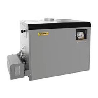
Low Temperature
PENNANT
Hydronic Boiler
Model PNCH
Water Heater
Model PNCV
This product must be installed and serviced by a professional service technician,
FOR YOUR SAFETY:
qualified in hot water boiler installation and maintenance. Improper installation and/or operation could
create carbon monoxide gas in flue gases which could cause serious injury, property damage, or
death. Improper installation and/or operation will void the warranty. For indoor installations, as an
additional measure of safety, Laars strongly recommends installation of suitable Carbon Monoxide
detectors in the vicinity of this appliance and in any adjacent occupied spaces.
If the information in this manual is not
followed exactly, a fire or explosion may
result causing property damage, personal
injury or loss of life.
Do not store or use gasoline or other
flammable vapors and liquids in the vicinity of
this or any other appliance.
WHAT TO DO IF YOU SMELL GAS
• Do not try to light any appliance.
• Do not touch any electrical switch; do not
use any phone in your building.
• Immediately call your gas supplier from
a nearby phone. Follow the gas supplier's
instructions.
• If you cannot reach your gas supplier, call
the fire department.
Installation and service must be performed
by a qualified installer, service agency, or gas
supplier.
™
WARNING
Heating Systems Company
A subsidiary of
Assurez-vous de bien suivres les instructions
données dans cette notice pour réduire au
minimum le risque d'incendie ou d'explosion ou
pour éviter tout dommage matériel, toute blessure
ou la mort.
Ne pas entreposer ni utiliser d'essence ni d'autres
vapeurs ou liquides inflammables dans le voisinage
de cet appareil ou de tout autre appareil.
QUE FAIRE SI VOUS SENTEZ UNE ODEUR DE GAZ:
• Ne pas tenter d'allumer d'appareils.
• Ne touchez à aucun interrupteur. Ne pas vous
servir des téléphones dansle bâtiment où vous
trouvez.
• Appelez immédiatement votre fournisseur de
gaz depuis un voisin. Suivez les instructions
du fournisseur.
• Si vous ne pouvez rejoindre le fournisseur de
gaz, appelez le sservice des incendies.
L'installation et l'entretien doivent être assurés par
un installateur ou un service d'entretien qualifié ou
par le fournisseur de gaz.
®
®
BRADFORD WHITE
Corporation
Document 1204E
AVERTISSEMENT
Advertisement
Table of Contents

Related Manuals for Laars pennant PNCH


Summary of Contents for Laars pennant PNCH
- Page 1 Improper installation and/or operation will void the warranty. For indoor installations, as an additional measure of safety, Laars strongly recommends installation of suitable Carbon Monoxide detectors in the vicinity of this appliance and in any adjacent occupied spaces.
-
Page 2: Table Of Contents
LAARS Heating Systems Page 2 TABLE OF CONTENTS SECTION 1. General Information SECTION 5. Electrical Connections Introduction ............3 Main Power ............ 20 Model Identification .......... 4 5.1.1 Sizes 500-1500 ..........21 Warranty ............4 5.1.2 Sizes 1750-2000 ..........21 Dimensions ............ -
Page 3: Section 1. General Information
à installation, operation and maintenance of both défaut de quoi la garantie fournie par Laars Heating products. Where differences exist between the Systems serait annulée. L’installation doit être application of the appliances and their operation, conforme aux exigences de la réglementation locale... -
Page 4: Model Identification
Installation Code", CSA B149.1, latest edition and all 1.3 Warranty applicable local codes as required by the AHJ. Laars Heating Systems’ appliances are covered All electrical wiring is to be done in accordance with: by a limited warranty. Owners should submit online 1). - Page 5 Low Temperature Pennant Page 5 INLET OUTLET PUMP TOP VIEW 3 WAY ACTUATOR TEMPERATURE SWITCH FLOW SWITCH 19.7 41.5 35.3 PUMP 13.7 13.7 12.4 13.8 20.24 7.75 29.3 LEFT SIDE VIEW FRONT VIEW RIGHT SIDE VIEW Ø Ø Dimensions shown in inches cm REAR VIEW Vent...
-
Page 6: Locating Pump-Mounted Water Heater With Respect To Storage Tank(S)
LAARS Heating Systems Page 6 above grade such that blockage of the terminal from 1.7 Locating Pump-Mounted Boiler with accumulated debris or precipitation is prevented. Respect to Return/Supply Header The dimensions and requirements that are shown For the best results, Pennant should be located... -
Page 7: Section 2. Venting And Combustion Air
When taken from the wall, it the National Fuel Gas Code, ANSI Z223.1. In Canada, must be taken from out-of-doors by means of the Laars the applicable sections of the Natural Gas and Propane horizontal wall terminal (see Table 2). -
Page 8: Venting
LAARS Heating Systems Page 8 (negative) 0.1 in. w.c. linear run. Subtract 10 allowable linear feet (3.0m) for If using a power venter for any type of Category every additional elbow used (see Table 2). When fewer I venting, the draft should be set between (negative) than 3 elbows are used, the maximum linear pipe 0.01 and 0.05 in. -
Page 9: Category Iii Vent
LAARS product, Locate the vent terminal so that it cannot be please call Applications Engineering at the Rochester blocked by snow. - Page 10 LAARS Heating Systems Page 10 U.S. Installations (see note 1) Canadian Installations (see note 2) A= Clearance above grade, veranda, porch, 12 inches (30 cm) 12 inches (30 cm) deck, or balcony B= Clearance to window or door that may...
- Page 11 Low Temperature Pennant Page 11 3 feet (0.9m) horizontally from the combustion however, that during said thirty (30) day air terminal, and locate the vent terminal at least period, a battery operated carbon monoxide 1 foot (0.3m) above the combustion air terminal. detector with an alarm shall be installed.
-
Page 12: Side Wall Combustion Air Terminal
Visually inspect the venting system for proper 2.3.2 Side Wall Combustion Air Terminal size and horizontal pitch and determine there is The Laars side wall combustion air terminal non blockage or restriction, leakage, corrosion (listed in Table 2) must be used when the unit takes and other deficiencies which could cause an its combustion air through a duct from a side wall. -
Page 13: Vent Terminals For Outdoor Units
Low Temperature Pennant Page 13 conforms with the National Fuel Gas Code, Tout mauvais fonctionnement du système ANSI Z223.1/NFPA 54 and/or CSA B149.1, d'évacuation commun devrait être corrigé Natural Gas and Propane Installation Codes. de façon que l'installation soit conforme au When resizing any portion of the common National Fuel Gas Code, ANSI Z223.1/NFPA venting system, the common venting system... -
Page 14: Section 3. Gas Supply And Piping
LAARS Heating Systems Page 14 SECTION 3. All threaded joints should be coated with piping compound resistant to action of liquefied Gas Supply and Piping petroleum gas. The appliance and its individual shutoff valve 3.1 Gas Supply and Piping must be disconnected from the gas supply piping... - Page 15 Low Temperature Pennant Page 15 WARNING: THIS DRAWING SHOWS SUGGESTED PIPING CONFIGURATION AND VALVING, CHECK System WITH LOCAL CODES AND ORDINANCES FOR System Pump ADDITIONAL REQUIREMENTS. Return System Supply PRIMARY/SECONDARY MANDATORY FOR ALL VARIABLE FLOW SYSTEMS. INSTALL AIR VENTS AT HIGH POINTS IN SYSTEM. PIPING &...
-
Page 16: Section 4A
LAARS Heating Systems Page 16 SECTION 4A. size as boiler outlet), with a normal number of fittings. The boilers must be piped in a primary-secondary sys- Water Connections — tem, such that the boiler’s pump only serves the boiler. Pennant Boiler Figures 4 and 5 show examples of this type of piping. -
Page 17: Section 4B. Water Connections
Contact a Pumps used are sized for soft, normal or hard water, so make sure the unit matches the water quality of the Laars representative if you have questions or concerns installation. about water quality. - Page 18 Any time a result in leaking or flooding conditions. heater is subjected to freezing conditions, and the Contact the local factory representative or Laars for additional information. GPM Water Flow Temperature Rise °F LPM Water Flow Temperature Rise °C...
- Page 19 Low Temperature Pennant Page 19 Figure 7. Suggested Piping — Multiple Water Heaters, One Tank. Figure 8. Suggested Piping — One Water Heater, Multiple Tanks.
-
Page 20: Section 5. Electrical Connections
LAARS Heating Systems Page 20 Figure 9. Suggested Piping — Multiple Water Heaters, Multiple Tanks. SECTION 5. AVERTISSEMENT Electrical Connections L’appareil doit être relié à la terre conformément aux exigences de la réglementation locale ou, en l’absence d’une telle réglementation, à la plus WARNING récente édition du National Electrical Code (Code... -
Page 21: Main Power
Low Temperature Pennant Page 21 Single pole switches, including those of safety on the Pennant temperature control at the factory. controls and protective devices must not be wired in a External Alarm: The field terminal strip has grounded line. terminals for a dry contact that is closed when the All electrical connections are made in the field ignition control locks out. -
Page 22: Low Water Cut-Off
LAARS Heating Systems Page 22 5.3 Low Water Cut-Off When this boiler is installed above radiation Note: This boiler is a water tube boiler that level, it is required that a Low Water Cut-Off (LWCO) requires water flow through the heat exchanger for be installed unless this requirement is superceded by proper operation. - Page 23 Low Temperature Pennant Page 23...
- Page 24 LAARS Heating Systems Page 24...
- Page 25 Low Temperature Pennant Page 25...
- Page 26 LAARS Heating Systems Page 26...
- Page 27 Low Temperature Pennant Page 27...
-
Page 28: Section 6. Operating Instructions
LAARS Heating Systems Page 28 SECTION 6. attempting to light, for four (4) seconds, and then will de-energize. The unit will go into lockout Operating Instructions mode. Second, turn the power off and then on again, open the manual gas valve and allow the 6.1 Filling the Boiler System... -
Page 29: Temperature (Operating) Control
Low Temperature Pennant Page 29 unless the flame sensor detects a flame, the gas valves By depressing the upper left hand button at will close and the ignition module will either attempt any time during the programming, the menu may be ignition again (up to three times) or will lockout (if the returned to the beginning. -
Page 30: Programming Parameters-Water Heaters
LAARS Heating Systems Page 30 oAH – Maximum Setpoint CAUTION This is the maximum allowable calculated Should overheating occur or the gas supply fail to setpoint, regardless of outdoor temperature. shut off, turn off the manual gas control valve to the Default is 190°F. -
Page 31: High Altitude Adjustment And Set Up
Low Temperature Pennant Page 31 necessary. The manifold gas pressure must be (for high altitude only, standard operating pressure is 2.5” W.C. (0.62kPa). 2.5 in. W.C. (0.62 kPa)). It is adjusted by removing the Complete the setup by checking the CO at the slotted cap on the gas valve and turning the adjustment outlet of the unit. -
Page 32: Section 7. Maintenance
7.2 Appliance Maintenance and Component Description Only genuine Laars replacement parts should be used. Caution Label all wires prior to disconnection when servicing controls. Wiring errors can cause improper and dangerous operation. -
Page 33: Filter
Low Temperature Pennant Page 33 7.2.2 Filter the mounting screws. Remove the screws, and pull the switch off the control panel. Remove the capillary The filter used in the Pennant is washable. Since the filter is washable, it will only need replacement and bulb from the thermal well located in the header. -
Page 34: Ignitor
LAARS Heating Systems Page 34 ate for powering the gas valves. It also controls the blower out. Replace blower in reverse order, ensuring blower’s pre-purge and post-purge. Pennant models that all joints are made correctly. After replacement, 500 through 1000 have one ignition control. Models ensure that the unit operates properly, by following the 1250 through 2000 have two ignition controls. -
Page 35: Section 8. Trouble Shooting
Low Temperature Pennant Page 35 SECTION 8. Disconnect the electrical supply to the unit. Turn off the gas supply by closing the manual gas Trouble Shooting valve on the heater. Disconnect and remove the wires, conduit and 8.1 Resolving Lockouts sensors from all components that are attached to There are many causes of lockouts. -
Page 36: Short Cycling - Water Heater
Appliances operating with an improper air/ 9.1 General Information fuel ratio are very inefficient and consequently, have To order or purchase parts for the Laars Pennant, very high gas consumption. Because efficiency is contact your nearest Laars dealer or distributor. If... - Page 37 Low Temperature Pennant Page 37...
- Page 38 LAARS Heating Systems Page 38...
- Page 39 Low Temperature Pennant Page 39...
- Page 40 LAARS Heating Systems Page 40...
- Page 41 Low Temperature Pennant Page 41...
- Page 42 LAARS Heating Systems Page 42 DETAIL "A" TYPICAL CONTROLLER DETAIL “A” COMPONENTS TYPICAL CONTROLLER COMPONENT Figure 19. Sheet Metal Components.
- Page 43 Low Temperature Pennant Page 43 NOTES: Model 2000 shown for reference. SEE ENLARGEMENT (DETAIL “A”) ON PREVIOUS PAGE ON NEXT PAGE SEE ENLARGEMENT (DETAIL “B”) ON NEXT PAGE 36/37 34/35 38/39 27/A/B Figure 20. Internal Components.
- Page 44 800.900.9276 • Fax 800.559.1583 Customer Service and Product Support: Industrial Way, Rochester, NH 03867 • 603.335.6300 • Fax 603.335.3355 Headquarters: 1869 Sismet Road, Mississauga, Ontario, Canada L4W 1W8 • 905.238.0100 • Fax 905.366.0130 www.LAARS.com Litho in U.S.A. © Laars Heating Systems 1505 Document 1204E...
Need help?
Do you have a question about the pennant PNCH and is the answer not in the manual?
Questions and answers