Table of Contents
Advertisement
Available languages
Available languages
Advertisement
Chapters
Table of Contents

Related Manuals for Inter-m EMI-300


Summary of Contents for Inter-m EMI-300
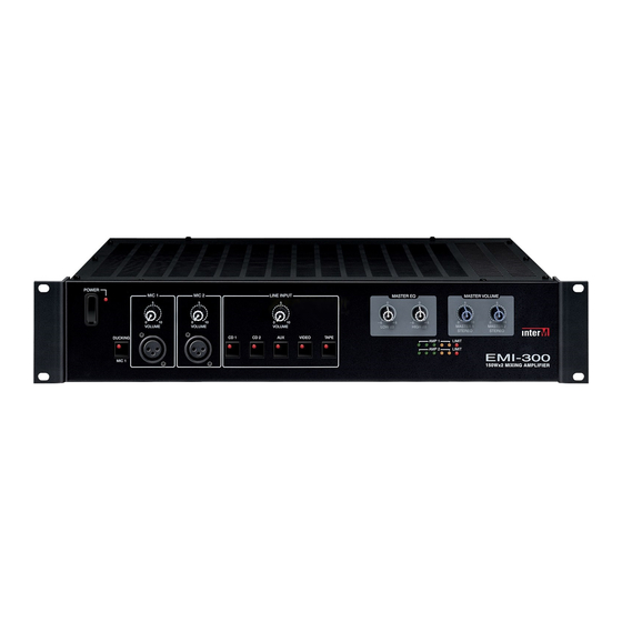
- Page 1 EMI-300 7-Channel 2 x 150W Mixing Amplifier EMI-300 150Wx2 MIXING AMPLIFIER...
-
Page 2: Table Of Contents
Contents Contents Welcome Warning..........................1 Unpacking ..........................2 Installation Environment ..........................2 Important Safety Instructions ....................2 Features ..........................3 Operation ..........................3 Panel Front Panel..........................4 Rear Panel ..........................7 Operational Modes ......................9 Speakers Connections ....................... 10 Connection of Sound Sources ..................13 Initial Settings ........................14 Ducking Functions .......................14 Insert I/O Jacks... -
Page 3: Warning
Care should be taken so than objects do not fall and liquids are not spilled into the enclosure through openings.” EMI-300... -
Page 4: Unpacking
S3125A S3125A EMI-300... -
Page 5: Features
Keep volume levels at minimum gain and equalization set to 0dB position before switching on. NOTE: The system’s operation is delayed by approximately three seconds after pressing the AC Mains power switch. This is due to the built-in protection circuitry, designed to protect the speakers and other system components. EMI-300... -
Page 6: Front Panel
This switch is used to switch the unit on and off. When the unit is on, the corresponding power indicator LED is lit. CAUTION: Decrease the MASTER gain levels (7) and (8) before switching the EMI-300 on or off. 2. MIC 1 VOLUME CONTROL This knob controls the MIC 1 channel’s input signal level. - Page 7 VIDEO input channels are on the rear panel, with the level being controlled both by a rear panel stereo Line Input Gain Control (Rear Panel 26) and a front panel master Line Input Volume Control (Front Panel 4). This input is intended for the audio output of a video playback deck or VCR. EMI-300...
- Page 8 The six-segment LED meter indicates the signal levels being sent to AMP 1 and AMP 2. When the sixth segment “LIMIT” LED is lit, it indicates that the signal is near clipping, and that the limiter circuitry has engaged to prevent overload distortion. EMI-300...
-
Page 9: Rear Panel
20. MASTER 2 OUT The signal at this output is identical to the signal sent to AMP 1 and AMP 2 when the EMI-300 is in stereo mode. Connect these balanced +4dB XLR outputs to an additional power amp or powered speakers for additional power or monitoring capability, or to a two-track tape recorder. - Page 10 Connect the line inputs of your mixdown deck to the REC OUT line outputs for recording your stereo mix. The signal output from the REC OUT is identical to the signal sent to the MASTER 1 output, yet is not affected by the setting of the MASTER EQ and MASTER VOLUME controls and works in every operational mode. EMI-300...
-
Page 11: Operational Modes
Operational Modes Operational Modes The EMI-300 can be operated in one of three modes—Stereo, Mono, or Bridge. Operational modes can be selected with the AMP ROUTING switch (22). Depending on the selected mode, your speakers must be connected in a specific way for the mode you have selected. First choose an operational mode that best suits your needs from the list below, and then connect your speakers as suggested. -
Page 12: Speakers Connections
Connection of Additional Speakers When connecting multiple speakers to the EMI-300, always observe the polarities to avoid phase problems and sound cancellation. In a network of speakers, all speakers should produce the same volume. This is a given when all cabinets have the same individual impedance and when the network has a symmetrical structure. - Page 13 Total impedances for Connect all '+' terminals on the speakers to the red black parallel wiring '+' terminal of the EMI-300 output and all '-' Single speaker terminals on the speakers to the black '-' terminal of impedance Amount of the EMI-300 output.
- Page 14 Both networks are wired so that the resulting total impedance equals the individual speaker impedance. If, for example, 4Ω speakers are used, the total impedance will also be 4Ω, which perfectly matches the EMI- 300 amplifiers. EMI-300...
-
Page 15: Connection Of Sound Sources
3-pin low or 1/4” high impedance jacks on channels 1-6. Please note that the low and high impedance inputs cannot be used simultaneously. 3. Switch devices on in the order they are connected to your EMI-300. Reverse the order when switching power off. -
Page 16: Initial Settings
Initial Settings Before switching on the EMI-300, set the gain controls of all used line inputs (26) to center position. Set the Before switching on the EMI-300, set the gain controls of all used line inputs (26) to center position. Set gain controls of all unused inputs to full counterclockwise position. -
Page 17: Master 2 Out
The level of this output depends on the setting of the MASTER 2 control. If you are operating your EMI-300 in stereo mode, you can use the MASTER 2 output to connect another If you are operating your EMI-300 in stereo mode, you can use the MASTER 2 output to connect another power amplifier for increasing your available system power. -
Page 18: Applications
RANDOM REPEAT ALL 1 DISCS PROG / REV RANDOM TRACK INDEX INTRO 10 11 12 13 14 -SKIP-SEARCH STOP/CLEAR PLAY/PAUSE PC-9335A PC 9335A PUBLIC ADDRESS LOGIC DOUBLE DECK Effect Processor PHONES MODEL NO. EMI-300 EMI-300 150Wx2 MIXING AMPLIFIER Microphones EMI-300... -
Page 19: Block Diagram
7-CHANNEL 2 X 150W MIXING AMPLIFIER Block Diagram Block Diagram EMI-300... -
Page 20: Specifications
Low......................100Hz, ±6dB, shelving type Phantom Power.........................+20VDC - GENERAL Power Source................. 100–120VAC or 220–240VAC; 50/60Hz ............(Supplied AC mains transformer depends on country requirements) Power Consumption ........................261W Weight ..........................13kg/28.6lb Dimensions ..............483(W)x90(H)x383(D)/19(W)x3.5(H)x15(D)inmm * Specifications and design subject to change without notice for product improvements. EMI-300... -
Page 21: Service
To obtain specific warranty information and available service locations contact Inter-M directly or the authorized Inter-M Distributor for your specific country or region. EMI-300... - Page 22 OC03 OC03 B370031 EMI-300 7-Channel 2 x 150W Mixing Amplifier EMI-300 150Wx2 MIXING AMPLIFIER...
- Page 23 Dank, dass sie sich für ein Produkt von Inter-M entschieden haben. Wir wünschen ihnen mit Ihrem neuen EMI-300 viel Spass und Erfolg. Bitte lesen sie diese Bedienungsanleitung vor Inbetriebnahme des Systems gründlich durch, um sich mit allen Funktionen vertraut zu machen.
-
Page 24: Sicherheitshinweise
• wenn das Gerät fallen gelassen oder das Gehäuse beschädigt wurde. Betreiben sie EMI-300 nicht in feuchter Umgebung. Setzen Sie die das Gerät nicht Regen oder Schnee aus. Betreiben sie das Gerät nicht in der Nähe von Hitzequellen (z.B. Heizkörper). -
Page 25: Frontseite
7-CHANNEL 2 X 150W MIXING AMPLIFIER Frontseite Frontseite EMI-300 150Wx2 MIXING AMPLIFIER 14 15 16 1. NETZSCHALTER 2. LAUTSTÄRKEREGLER FÜR MIKROFON 1 3. LAUTSTÄRKEREGLER FÜR MIKROFON 2 4. LAUTSTÄRKEREGLER FÜR LINE-EINGÄNGE Dieser Regler gilt für den jeweils ausgewählten Line-Eingang 5. BASS-REGLER Dieser Regler ist für alle Eingänge wirksam... - Page 26 Gleiche Spezifikationen wie Mikrofoneingang 1, jedoch ohne „Ducking” Funktion. Beide Mikrofoneingänge können gleichzeitig benutzt werden. - Auswahltaster für Line-Eingänge: Es ist jeweils nur ein Line-Eingang aktiv. 12. CD 1 13. CD 2 14. AUX 15. VIDEO (CASSETTENGERÄT) 16. TAPE 17. ANZEIGE FÜR AUSSTEUERUNG UND LIMITER EMI-300...
-
Page 27: Rückseite
Tieftonlautsprecher (Subwoofer) angeschlossen werden. Die Lautstärke dieses Ausganges ist von der Stellung des Master 1 Reglers abhängig. 22. SCHALTER FÜR EMI-300 BETRIEBSARTEN Mit diesem Schalter wird der EMI-300 zwischen den Betriebsarten Stereo, Mono und Bridge umgescheltet. Beachten sie beim Umschalten unbedingt die Hinweise auf den Seiten 28, 29 und 30. EMI-300... - Page 28 Einstellung sollten zunächst alle Vorregler in der Mittelstellung stehen, so dass ein Ausgleich nach oben oder unten möglich ist (s. Seite 31). 27. RECORDING-AUSGANG An diesem Stereo-Ausgang liegen alle aktiven Line-und Mikrofon-Signale an. Das Signal ist nur von den Mikrofonreglern (2) und (3) bzw. vom Line-Volumenregler (4) abhängig. EMI-300...
-
Page 29: Betriebsarten
Betriebsarten Betriebsarten Der EMI-300 kann in den 3 Betriebsarten Stereo, Mono und Bridge betrieben werden, die mit dem AMP ROUTING Schalter (22) angewählt werden. Da die Wahl der Betriebsart den Anschluss der Boxen beeinflusst, sollten sie als erstes eine zu ihrer Anwendung passende Betriebsart auswählen. Suchen sie aus den unten aufgeführten Anwendungen die für Sie passende heraus. -
Page 30: Anschluss Der Boxen
Impedanzen unter 4 Ohm können die Endstufen überlastet werden. ANSCHLUSS MEHRERER BOXEN Wenn mehrere Boxen an den EMI-300 angeschlossen werden, müssen deren Polari täten beachtet werden um Klangauslöschungen zu vermeiden. Beachten sie in den folgenden Anschlussbeispielen daher stets die korrekte Polarität (+ = Signal / - = Masse). -
Page 31: Anschluss Der Boxen(Forts.)
Reihen/Parallel-Netzwerke verwenden. Bei beiden Netzwerken ist die Gesamtimpedanz gleich den Einzelimpedanzen, d.h. bei Verwendung von Boxen mit 4 Ohm Impedanz ist die Gesamtimpedanz ebenfalls 4 Ohm und somit optimal an den EMI-300 angepasst. EMI-300... -
Page 32: Anschluss Der Klangquellen
Inbetriebnahme Inbetriebnahme Before powering up the emi-300, set the gain controls of all used line inputs (27) to center position. Set the Stellen sie die Pegel-Regler (26) aller benutzten Line-Eingänge zunächst auf Mittelstellung. Stellen sie die Pegel- gain controls of all unused inputs to full counterclockwise position. Set all gain controls on the front panel (2) Regler der unbenutzten Eingänge auf 0 (linker Anschlag). -
Page 33: Insert-Buchsen
The level of this output depends on the setting of the MASTER 2 der Stellung des MASTER 2 Reglers abhängig. control.If you are operating your EMI-300 in stereo mode, you can use the MASTER 2 output to connect Wird der EMI-300 im Stereo-Modus betrieben, kann über diesen Ausgang eine zweite Endstufe angeschlossen another power amplifier for increasing your available system power. -
Page 34: Technische Daten
Mono Sub Out ....................Filter: Tiefpass 100 Hz / 12 dB ........Ausgangsbuchse: XLR symmetrisch (1 = Masse, 2 = signal + (hot), 3 = signal - (cold)) Rec Out ..........................1 x Cinch (stereo) Klirrfaktor (THD) ..........................< 0.1% Frequenzgang ........................18 - 25.000 Hz Gewicht...............................13kg Abmessungen ......................383(B)x483(H)x90(T)mm ..............................19" / 2HE EMI-300... - Page 35 Inter-M, Ltd. (Korea) began operations in 1983. Since then, Inter-M has grown to become one of the largest manufacturers of professional audio and commercial sound electronics equipment in the world. Inter-M has gained worldwide recognition for its own branded products, as well as private label manufacturing of electronics sold under other names (OEM).
Need help?
Do you have a question about the EMI-300 and is the answer not in the manual?
Questions and answers