Inter-m A-60 Service Manual
Hide thumbs
Also See for A-60:
- Operation manual (13 pages) ,
- Operation manual (15 pages) ,
- Operating manual (13 pages)

Subscribe to Our Youtube Channel
Related Manuals for Inter-m A-60


Summary of Contents for Inter-m A-60
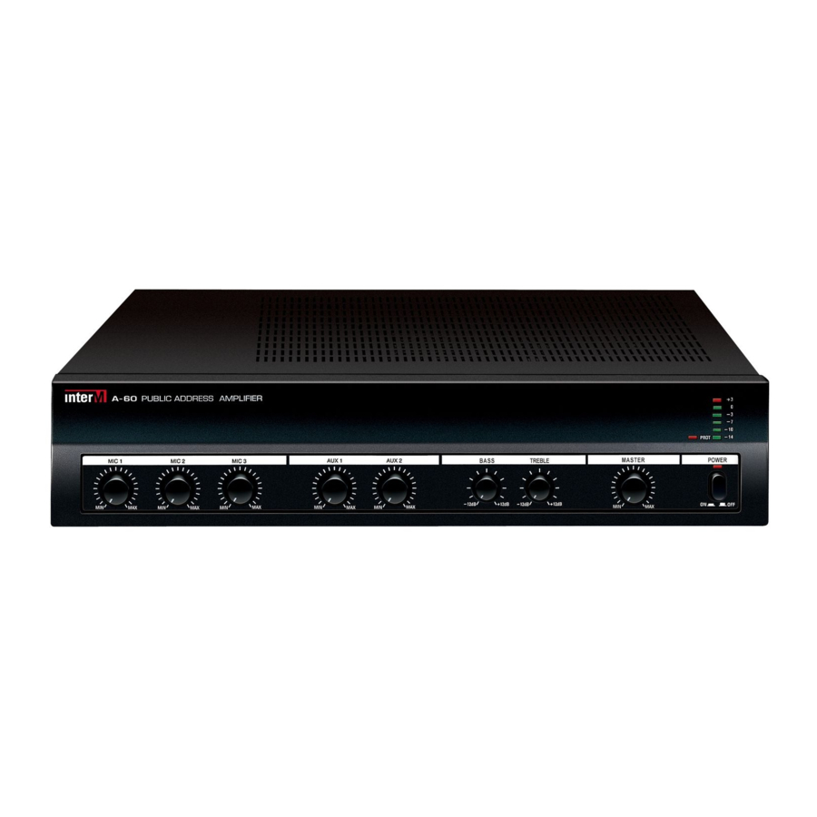
- Page 1 SERVICE MANUAL P U B L I C A D D R E S S AMPLIFIER A-60/120 www.inter-m.com MADE IN KOREA NO: 9007985000...
-
Page 2: Table Of Contents
Top and Bottom View of P.C. Board Wiring Diagram C. Adjustment A-60: Adjust VR11 so that the current through the R56 and R58 become 10 milliampere. When that Block Diagram voltage is 10 millivolt, the current becomes 10 milliampere. Schematic Diagram 8, 9 A-120: Adjust VR11 so that the current through the R56 and R58 become 5 milliampere. -
Page 3: Specifications
ELECTRICAL Ref No. Part No. Description Value Ref No. Part No. Description Value • Rated Output/Impedance ............A-60: 15.5V/4Ω, 70V/81.6Ω, 100V/166.7Ω C72-74 C81 3409247071-T CAP AF RSG 47UF 50V 6 P 47/50 MAIN B’D (4005181100) C117-118 ....................A-120: 21.9V/4Ω, 70V/40.8Ω, 100V/83.3Ω Q16-17... -
Page 4: Top And Bottom View Of P.c. Board
CAP MA 0.01UF 100V 0.01/100(M) C174 3609152120-T CAP MA 0.0015UF 100V J 0.0015/100(M) CON9 4355740621 CON ASS Y 3P 510MM A-60/120 CON ASS Y 3P (510MM) CON7 4355743319 CON ASS Y 5P (450MM) A-60/120 CON ASS Y 5P (450MM) CON8... -
Page 5: Wiring Diagram
WIRING DIAGRAM BLOCK DIAGRAM... -
Page 6: Schematic Diagram
SCHEMATIC DIAGRAM... -
Page 7: Exploded View Of Cabinet & Chassis/Mechanical Parts List
EXPLODED VIEW OF CABINET & CHASSIS/MECHANICAL PARTS LIST A-60/120 EXPLODED VIEW DWG PARTS, LIST PARTS NAME REMARK PARTS NO Q’TY 048521990611 A-60 FRONT PANEL 048521990612 A-120 INLAY 048573994111 KNOB CONTROL 048543998313 KNOB CONTROL 048543997011 KNOB PUSH 8543998110 VOLUME B’D 4005181110 OUTPUT LED B’D... -
Page 8: Ass'y Drawing
ASS’Y DRAWING Description Part No Q'ty Remark 048521990611 A-60 FRONT PANEL 048521990612 A-120 SW POWER 048543997210 CONTROL KNOB 048543997011 CONTROL KNOB 048543998313 INLAY 048573994111 TOP COVER 046122089610 CONTROL KNOB 048543997011 PHONE JACK 4438097310 RCA JACK 4P 4438095210 SPEAKER TERMINAL 4408193904... - Page 9 NOTE...
Need help?
Do you have a question about the A-60 and is the answer not in the manual?
Questions and answers